EP0369525B1 - Method for producing a leno or cross weaving texture - Google Patents
Method for producing a leno or cross weaving texture Download PDFInfo
- Publication number
- EP0369525B1 EP0369525B1 EP89202828A EP89202828A EP0369525B1 EP 0369525 B1 EP0369525 B1 EP 0369525B1 EP 89202828 A EP89202828 A EP 89202828A EP 89202828 A EP89202828 A EP 89202828A EP 0369525 B1 EP0369525 B1 EP 0369525B1
- Authority
- EP
- European Patent Office
- Prior art keywords
- plane
- thread
- stationary
- crossing
- line segment
- Prior art date
- Legal status (The legal status is an assumption and is not a legal conclusion. Google has not performed a legal analysis and makes no representation as to the accuracy of the status listed.)
- Expired - Lifetime
Links
Images


Classifications
-
- D—TEXTILES; PAPER
- D03—WEAVING
- D03C—SHEDDING MECHANISMS; PATTERN CARDS OR CHAINS; PUNCHING OF CARDS; DESIGNING PATTERNS
- D03C7/00—Leno or similar shedding mechanisms
- D03C7/06—Mechanisms having eyed needles for moving warp threads from side to side of other warp threads
Definitions
- the present invention relates to a method for producing a leno or cross weaving texture.
- Some methods belonging to a first type take advantage of the successive and alternate tensioning and releasing of two warp threads moving to both sides of another warp thread -- called "stationary-thread" --, slidingly connected with each other, so as to cause the crossing-thread(s) to shift to the one or to the other sides of the stationary-thread, with the desired textile effect of crossing of the crossing-thread(s) with the stationary-thread being consequently achieved.
- a method of a second type exploits, on the contrary, the combined action of a set of special heddles -- called "English leno or crossing weaving units" -- in order to obtain the successive crossing of the stationary-thread and of the crossing-thread for generating the leno or cross weaving texture.
- a set of special heddles called "English leno or crossing weaving units" -- in order to obtain the successive crossing of the stationary-thread and of the crossing-thread for generating the leno or cross weaving texture.
- the first type of methods some of which enable the speeds rendered possible by the modern needle weaving planes (more than 2,000 weft insertions per minute) to be fully exploited, mandatorily require that mechanisms be provided which make it possible some warp threads to be successively tensioned and released, with said warp threads undergoing strong stretches, and rendering more complex the initial threading of the threads through the same weaving plane.
- the purpose of the present invention is that of providing a solution for overcoming the limitations which affect the above said methods known from the prior art, and specifically the method known from EP-A-0 253 451, thus making it possible the actual capabilities of the modern weaving planes to be fully taken advantage of, while simultaneously simplifying their threading system and offering a high flexibility of realization.
- the line segment can be composed by any portions of at least one thread constituted by either natural or artificial fibres, which is destined to become a part of the fabric which is being formed, and is used for the specific function of realizing the shift of the crossing-thread from either side to the other side of the stationary-thread(s), by being moved in a per se known way by two healds situated on opposite sides relatively to said stationary-thread(s).
- Figure 1 relevant to the warp profile, shows the non-essential feature of the stationary-thread remaining always on one side relatively to the weft, indicated by the reference numeral 3 in its various insertions, around which, on the contrary, the crossing-thread 2 gets interlaced.
- Figures 3 and 4 show how the stationary-thread 1 and the crossing-thread 2 get arranged in practice owing to the effects of the tensions and of the natural flexibility of the threads which constitute the textile interlacement. From these figures, one will easily see that the definition of "crossing-thread” and “stationary-thread” loses its ground for being once that both of said threads.have been incorporated in the fabric, in that, as said Figures precisely show, in the finished fabric they cannot be any longer distinguished from each other.
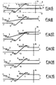
- Figure 5 and, in plan view, also Figure 6, show a first step of a first example of practical embodiment of the method according to the present invention in order to cross two warp threads, i.e., a crossing-thread 4 and a stationary-thread 7, with each other.
- the crossing-thread 4 is, threaded through the hole of a first heald 5, in the top position of a shed 6, whilst the stationary-thread 7 is in the opposite position, threaded first through the hole of a second heald 8 and then through the hole of a third heald 9 having a particular shape.
- the third heald 9 in this particular form of practical embodiment of the present invention, is provided with an arm 9a extending from it and along a short distance parallel to it, so as to define a gap 11.
- a length, or a portion 10, of the stationary thread 7, running between the threading holes of the two healds 8 and 9 which move it, constitutes a line segment.
- Said line segment 10 can be inclined, so as to cross a weaving plane, indicated by the character "C" in Figure 5, alternatively on the one and on the opposite side of the same weaving plane C, which is defined as the plane on which the fabric is formed,
- the inclined line segment 10 is such as to cause the crossing-thread 4 to alternatively shift to both sides of the stationary-thread 7.
- the inclination of the length, or line segment 10, of the stationary-thread 7 is such as to move the crossing-thread 4 to run, during its subsequent movement in order to come to the opposite position of the shed 6, along the surface of the segment 10, until said crossing-thread 4 enters the gap provided on the third heald 9.
- the line segment constituted by the segment 10 of the stationary thread 7 connects two planes, or two sets of planes, one only of these planes of the respective sets being indicated in chain line at A and B, these planes being perpendicular to the weaving plane C and laying parallel to the stationary-thread 7, on both sides of this latter.
- a beating reed 12 beats then a weft insertion 13, up to bring it to rest against the weft insertions already inserted in the fabric, before the healds 5,8 and 9 are moved in order to invert the positions of the threads in the shed 6.
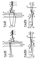
- Figure 7 and the respective plan view of Figure 8 show an intermediate time point, in which the shed 6 is practically closed, between the steps of the preceding Figures 5 and 6 and the step depicted in following Figures 9 and 10.
- the crossing-thread 4 has ended its sliding, and has entered the gap 11 of the third heald 9, thus getting shifted and coming to lay on a plane A perpendicular to the weaving plane C and parallel to the stationary-thread 7, but on the opposite side relatively to the side on which it was during the initial step shown in Figures 5 and 6, when it was lying on one plane from the set of planes B.
- Figures 13 and 14 show an intermediate step between the step shown by Figures 11 and 12, and the step shown by the subsequent Figures 15 and 16.
- the crossing-thread 4 is not deviated now, during its movement of shifting towards the opposite side of the shed 6, by the inclined segment 10 of the stationary-thread 4.
- Such a stationary-thread segment 10, with the herein shown inclination enables hence said crossing-thread 4 to simply completely move on a plane B perpendicular to the weaving plane C, without any motion components parallel to said weaving plane C, but it does not constitute, in this step of this particular form of practical embodiment of the present invention, a sliding line which may cause the crossing-thread 4 to shift parallelly to the weaving plane C.
- Figure 17 a schematic view can be seen of a portion of a leno or cross weaving texture, manufactured according to the exemplifying form of practical embodiment of the method proposed by the present invention, as disclosed by the Figures from 5 to 16.
- Figures from 18 to 22 and from 18a to 22a show another possible exemplifying form of a practical embodiment of the method proposed according to the present invention, in which for same components same reference numerals are used, and in which two warp threads 17 and 18 are provided, which are destined to act as stationary-threads.
- the line segment which can be inclined in order to cause the crossing-thread 4 to slide during its movement of shifting to the one, or to the other one, of the sides of the two stationary-threads 17 and 18, is actually constituted by respective different line segments 21 and 22 of the two different stationary threads 17 and 18.
- the crossing-thread 4 moved by the corresponding heald 5 is in the top position of the shed 6 and before going to the fabric being formed, runs above a first weft insertion 24, through a "V" region formed by the two segments 21 and 22 of the stationary threads 17 and respectively 18.
- each one of the lifted healds 19 and 20 relatively to the further, lowered, heald 23 determines the inclinations of both segments 21 and 22 of the stationary-threads 17 and 18 which, in their turn, cause the shifting of the crossing-thread 4 to the one side and to the other side of the further heald 23, and therefore of the stationary-threads 17 and 18 coming together into the hole of the heald 23, and exiting it on opposite sides.
- the movement of the further heald 23 is decided on the basis of the desired textile interlacement between the weft insertions 24 and the stationary-threads 17 and 18.
- the crossing-thread 4 by getting crossed with the metal blade 34, is obliged to form loop portions, or loops, 39, around it, which loops are of size and shape corresponding to those of the cross-section of the metal blade 34 so that, as the fabric gets disengaged from the metal blade 34, only the loops remain, which loops precisely protrude outwards from the fabric with a stationary-thread 28 being arranged inside them. More precisely, the line segment for keeping portions of the crossing-thread 4 raised, is positioned at at least one portion of the stationary-thread 28 and indicated by the reference numeral 31, and under the thread 4.
- the crossing-thread 4 is in the bottom position of the shed 6, looking at the figure, and is before the metal blade 34 and the stationary-thread 28 positioned above a weft insertion 35.
- a portion, or line segment, 31 of the stationary thread 28, thanks to the lowered position of a heald 29 and to the simultaneously lifted position of a heald 30, is inclined towards a plane B on the side of the heald 29.
- the stationary-thread 28 runs through the holes of such healds 29 and 30 before also running through the hole 33 of the metal blade 34 which returns it back to a stable position, parallel to the weaving plane C, alongside of the same metal blade 34.
- the crossing-thread 4 After a weft insertion 37, in Figures 26 and 26a, the crossing-thread 4 returns back to its top position, with the healds 29 and 30 which control the stationary-thread 28 simultaneously inverting again their position, so that the inclination of the segment 31 will be now in the suitable direction for a further crossing to be caused to occur between the stationary-thread 28 and the crossing-thread 4.
- the weaving method called "gauze weaving” has in fact been used here for the only purpose of creating the loops 39 thanks to the crossing of the crossing-thread 4 which constitutes them, with the metal blade 34 replacing, at least for a certain length inside the fabric, the stationary-thread.
- Such a method is essentially characterized by the use of one or more line segments which can be alternatively inclined towards the one side, or towards the other side, of the at least one stationary-thread provided, and constituted by lengths of warp threads on whose surface the crossing-thread is caused to slide, thus being alternatively shifted, owing to the effect of such different inclinations, to the one side and to the other side of the same at least one stationary-thread: only thanks to such one or more inclined sliding length(s) the possibility is given of accomplishing the gauze interlacement in all of its possible and imaginable variants, due to the function performed by these lengths, of causing the crossing-thread, according to presettable sequential cycles, to slide to opposite regions of the shed, and to opposite half-weaving planes relatively to the stationary-thread.
- the same at least one inclined sliding length can be accomplished, and/or thought of, in several ways and positions.
- the essential characteristic thereof is that it should perform the hereinabove illustrated functions in order that the leno or cross weaving texture can be obtained by means of the sliding which said inclined length will cause the crossing-thread to undergo, in order that said crossing-thread is brought to cross with the stationary-thread.
- the stationary-thread can be accompanied by other warp threads, with each of said threads performing its independent movements in its own shed and perpendicularly to the weaving plane: the crossing-thread will perform its movements getting crossed with this set of warp threads.
Landscapes
- Engineering & Computer Science (AREA)
- Textile Engineering (AREA)
- Looms (AREA)
- Treatments For Attaching Organic Compounds To Fibrous Goods (AREA)
- Woven Fabrics (AREA)
- Adornments (AREA)
- Knitting Of Fabric (AREA)
Abstract
Description
- The present invention relates to a method for producing a leno or cross weaving texture.
- As "gauze-weaving" that weaving method is defined in which a warp thread gets crossed with another warp thread, on the one side and on the other side, i.e., "before and behind", relatively to said another warp thread in order to obtain the gauze effect; said two warp threads are respectively denominated the "crossing-thread" and the "stationary-thread". These names are due not so much to the function, or to the arrangement of the threads in the obtained fabric, in which they can be difficultly distinguished from each other, in that they are pairs of mutually crossing threads, but are useful in order to clarify the idea of the movement they make during the weaving; in other terms, the names express the concept that the "crossing-thread" is shifted to the one and to the other side of the "stationary-thread", whereby also this latter can move, but with a direction of movement substantially perpendicular to the weaving plane, and not parallel to it.
- Various methods for producing the above textile interlacement are known. Some methods belonging to a first type take advantage of the successive and alternate tensioning and releasing of two warp threads moving to both sides of another warp thread -- called "stationary-thread" --, slidingly connected with each other, so as to cause the crossing-thread(s) to shift to the one or to the other sides of the stationary-thread, with the desired textile effect of crossing of the crossing-thread(s) with the stationary-thread being consequently achieved.
- A method of a second type exploits, on the contrary, the combined action of a set of special heddles -- called "English leno or crossing weaving units" -- in order to obtain the successive crossing of the stationary-thread and of the crossing-thread for generating the leno or cross weaving texture. Such a method is disclosed in EP-A-0 253 451.
- The first type of methods, some of which enable the speeds rendered possible by the modern needle weaving planes (more than 2,000 weft insertions per minute) to be fully exploited, mandatorily require that mechanisms be provided which make it possible some warp threads to be successively tensioned and released, with said warp threads undergoing strong stretches, and rendering more complex the initial threading of the threads through the same weaving plane.
- The use of the special "English-crossing" units, on the contrary, strongly limits the speed of the modern weaving planes, causing said speed to be decreased down to less than a half of its maximum available value and, owing to the thickness of the healds used, makes it necessary particularly strong and valuable threads to be used, with a considerable increase in raw material costs.
- The purpose of the present invention is that of providing a solution for overcoming the limitations which affect the above said methods known from the prior art, and specifically the method known from EP-A-0 253 451, thus making it possible the actual capabilities of the modern weaving planes to be fully taken advantage of, while simultaneously simplifying their threading system and offering a high flexibility of realization.
- This purpose, according to the present invention, is achieved by a method having the features of claim 1.
- The line segment can be composed by any portions of at least one thread constituted by either natural or artificial fibres, which is destined to become a part of the fabric which is being formed, and is used for the specific function of realizing the shift of the crossing-thread from either side to the other side of the stationary-thread(s), by being moved in a per se known way by two healds situated on opposite sides relatively to said stationary-thread(s).
- The method according to the present invention is disclosed in greater detail in the following by referring to the hereto attached drawings which illustrate, for merely exemplifying and non-limitative purposes and in a schematic way, some interlacings which can be accomplished by means of the method.
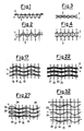
- Figures 1 and 2 show a theoretical graphic representation of respectively the warp profile and the textile pattern relevant to two threads which generate a leno or cross weaving texture of the simplest and most known type, in which the stationary-thread is not tied with the weft insertions,
- Figures 3 and 4 are, on the contrary, a pictorial representation of the actual mutual relationship in which said two gauze-woven threads are arranged, respectively according to the warp profile and the textile pattern, in a known leno or cross weaving texture.
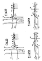
- Figures 5, 7, 9, 11, 13 and 15 show the steps of a method according to the present invention for obtaining a leno or cross weaving texture between a crossing-thread and a stationary-thread, using the same stationary-thread in order to accomplish the inclined Line segment,
- Figures 6, 8, 10, 12, 14 and 16 show plan views of the arrangement of the healds and of the threads during the various steps of the method respectively depicted in Figures 5, 7, 9, 11 and 13,
- Figure 17 shows a plan view of the textile interlacement which can be accomplished by means of the method shown in Figures from 5 to 16,
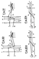
- Figures 18, 19, 20 and 21 show another exemplifying form of practical embodiment of the method according to the present invention in order to obtain a leno or cross weaving texture between one crossing-thread and two stationary-threads, wherein both of said stationary-threads realize the inclined line segment,
- Figures 18a, 19a, 20a and 21a are plan views of the arrangement of the healds and of the threads in the various steps of the method as respectively depicted in the preceding Figures from 18 to 21,
- Figure 22 shows a plan view of the textile interlacement which can be accomplished by means of the method shown in Figures from 18 to 21,
- Figures 23, 24, 25 and 26 show how it is possible to produce, according to the present invention, a fabric having loops protruding outwards from its surface (of the same type as of the fabric useable for contact-fastenings of the so-said "hook and loop" type), using, for the inclined line segment, a stationary-thread which remains inside the same loops,
- Figures 23a, 24a, 25a and 26a show plan views of the arrangement of the healds and of the threads in the various steps of the method respectively depicted in the preceding Figures from 23 to 26,
- Figure 27 shows a plan view of the textile interlacement which can be accomplished by means of the method shown in Figures from 23 to 26,
- Figures 28, 29, 30 and 31 show a further example of how by means of the method according to the present invention a fabric can be accomplished, which is provided with loops protruding from its surface, but in this case, in order to define the inclined line segment, a warp thread is used, which will not become a part of the end leno or cross weaving texture, but will become a part of the base fabric,
- Figures 28a, 29a, 30a and 31a show plan views of the arrangement of the healds and of the threads during the various steps of the method respectively shown in the preceding Figures from 28 to 31,
- Figure 32 shows a plan view of the textile interlacement which can be produced by means of the method shown in Figures from 28 to 31.
- Reference is first made to Figures 1 and 2 in order to show the theoretical mutual arrangement of the threads in case of a known leno or cross weaving texture in which a thread 2, denominated "crossing-thread" gets crossed with a thread 1, denominated "stationary-thread".
- Figure 1, relevant to the warp profile, shows the non-essential feature of the stationary-thread remaining always on one side relatively to the weft, indicated by the
reference numeral 3 in its various insertions, around which, on the contrary, the crossing-thread 2 gets interlaced. - The textile pattern shown in Figure 2 makes it possible to see the feature -- essential for the gauze interlacement -- of the crossing-thread 2 getting crossed with the stationary-thread 1, by being alternatively shifted, according to predetermined sequences, to the one and to the other side of the same stationary thread 1. The action of this crossing, as one will easily understand, fixes both of these threads in the fabric much better than the same threads would do by getting tied with the weft insertions, while remaining parallel to each other. It is precisely this feature which characterizes the so-said "leno or cross weaving texture"; in fact, the same word "leno" means "light open texture fabric", i.e. a fabric in which groups of two warp threads, even spaced apart from each other by a few millimetres, in case they were not suitably fixed by means of said interlacement to the weft insertions, would slide along these latter, in such a way as to eliminate the desired textile effect.
- Figures 3 and 4 show how the stationary-thread 1 and the crossing-thread 2 get arranged in practice owing to the effects of the tensions and of the natural flexibility of the threads which constitute the textile interlacement. From these figures, one will easily see that the definition of "crossing-thread" and "stationary-thread" loses its ground for being once that both of said threads.have been incorporated in the fabric, in that, as said Figures precisely show, in the finished fabric they cannot be any longer distinguished from each other.
- Figure 5, and, in plan view, also Figure 6, show a first step of a first example of practical embodiment of the method according to the present invention in order to cross two warp threads, i.e., a crossing-
thread 4 and a stationary-thread 7, with each other. - The crossing-
thread 4 is, threaded through the hole of afirst heald 5, in the top position of ashed 6, whilst the stationary-thread 7 is in the opposite position, threaded first through the hole of asecond heald 8 and then through the hole of athird heald 9 having a particular shape. In fact, thethird heald 9 in this particular form of practical embodiment of the present invention, is provided with anarm 9a extending from it and along a short distance parallel to it, so as to define agap 11. A length, or aportion 10, of thestationary thread 7, running between the threading holes of the twohealds line segment 10 can be inclined, so as to cross a weaving plane, indicated by the character "C" in Figure 5, alternatively on the one and on the opposite side of the same weaving plane C, which is defined as the plane on which the fabric is formed, - The
inclined line segment 10 is such as to cause the crossing-thread 4 to alternatively shift to both sides of the stationary-thread 7. - In the figure taken into consideration herein, the inclination of the length, or
line segment 10, of the stationary-thread 7 is such as to move the crossing-thread 4 to run, during its subsequent movement in order to come to the opposite position of theshed 6, along the surface of thesegment 10, until said crossing-thread 4 enters the gap provided on thethird heald 9. On examining Figure 6, one will observe that the line segment constituted by thesegment 10 of thestationary thread 7 connects two planes, or two sets of planes, one only of these planes of the respective sets being indicated in chain line at A and B, these planes being perpendicular to the weaving plane C and laying parallel to the stationary-thread 7, on both sides of this latter. - A beating
reed 12, only shown in this Figure in order to simplify the following figures, beats then aweft insertion 13, up to bring it to rest against the weft insertions already inserted in the fabric, before thehealds shed 6. - Figure 7 and the respective plan view of Figure 8 show an intermediate time point, in which the
shed 6 is practically closed, between the steps of the preceding Figures 5 and 6 and the step depicted in following Figures 9 and 10. - What above said facilitates the comprehension of these Figures, whose importance is particularly due to the fact that they evidence how the crossing-
thread 4, having begun its sliding along the surface of theinclined segment 10 of the stationary-thread 7, has already laterally moved in the direction of the slope of theinclined segment 10. In fact, the crossing-thread 4 is shifted from the trajectory in a plane perpendicular to the weaving plane C, which it would otherways run along as a consequence of the only effect of the movement of theheald 5 through which it runs, thanks to the particular shape of thespecial heald 9 and to its position relatively to the position of theheald 5. - In the step shown in Figures 9 and 10, in fact, the crossing-
thread 4 has ended its sliding, and has entered thegap 11 of thethird heald 9, thus getting shifted and coming to lay on a plane A perpendicular to the weaving plane C and parallel to the stationary-thread 7, but on the opposite side relatively to the side on which it was during the initial step shown in Figures 5 and 6, when it was lying on one plane from the set of planes B. - The only difference between the just discussed step and the step of Figures 11 and 12 is the inversion of position in the
shed 6, of the crossing-thread 4, displaced by theheald 5, and of the stationary-thread 7, displaced by thehealds segment 10 is placed now in a substantially horizontal position in the bottom side of theshed 6. One should furthermore observe, above all, the coming out of the crossing-thread 4 from thegap 11, with said crossing-thread 4 being consequently returned back onto the vertical plane B perpendicular to the weaving plane C which is on the same side of the stationary-thread 7 and of theheald 5 which controls it. - Also Figures 13 and 14 show an intermediate step between the step shown by Figures 11 and 12, and the step shown by the subsequent Figures 15 and 16. One may easily observe here that the crossing-
thread 4 is not deviated now, during its movement of shifting towards the opposite side of theshed 6, by theinclined segment 10 of the stationary-thread 4. Such a stationary-thread segment 10, with the herein shown inclination, enables hence said crossing-thread 4 to simply completely move on a plane B perpendicular to the weaving plane C, without any motion components parallel to said weaving plane C, but it does not constitute, in this step of this particular form of practical embodiment of the present invention, a sliding line which may cause the crossing-thread 4 to shift parallelly to the weaving plane C. - In fact, only during the end portion of such a movement, i.e., during the step as shown in Figures 15 and 16, the crossing-
thread 4 comes to rest on theinclined segment 10 of the stationary-thread 7 and, by sliding along the surface thereof, gets slightly shifted C from its trajectory perpendicular to the weaving plane C. This is just a case which is due to a particular dimensioning of the strokes of thehealds - In Figure 17 a schematic view can be seen of a portion of a leno or cross weaving texture, manufactured according to the exemplifying form of practical embodiment of the method proposed by the present invention, as disclosed by the Figures from 5 to 16.
- Figures from 18 to 22 and from 18a to 22a show another possible exemplifying form of a practical embodiment of the method proposed according to the present invention, in which for same components same reference numerals are used, and in which two
warp threads thread 4 to slide during its movement of shifting to the one, or to the other one, of the sides of the two stationary-threads different line segments stationary threads - In Figure 18, and in the plan view of Figure 18a, the crossing-
thread 4, moved by thecorresponding heald 5, is in the top position of theshed 6 and before going to the fabric being formed, runs above afirst weft insertion 24, through a "V" region formed by the twosegments stationary threads 17 and respectively 18. Thesestationary threads shed 6, moved by therespective healds further heald 23, which has a special shape, and is destined to move them inside theshed 6. - The relative position of each one of the
lifted healds heald 23 determines the inclinations of bothsegments threads thread 4 to the one side and to the other side of thefurther heald 23, and therefore of the stationary-threads heald 23, and exiting it on opposite sides. The movement of thefurther heald 23 is decided on the basis of the desired textile interlacement between theweft insertions 24 and the stationary-threads - On examining Figures 19 and 19a, one can observe that the lowering of the
heald 19 caused thesegment 21 of the stationary-thread 17 to get inclined in such a way that the crossing-thread 4, by sliding along the surface of this inclined thread portion during its movement of shifting towards the opposite position in theshed 6, has moved, relatively to thefurther heald 23, and therefore relatively to both of the stationary-threads heald 19 to lie on a plane A as disclosed in the preceding example perpendicular to the weaving plane C. In other terms, the crossing-thread 4 has moved to the same side from which the stationary-thread 17 comes, and it was initially caused to slide towards that side by the opposite inclination of theinclined segment 22 of the stationary-thread 18. - After a
further weft insertion 25, a situation at all similar to the situation of Figure 18 arises again. This situation is shown in Figures 20 and 20a and is easily understood from the examination of said Figures. The only change is that the crossing-thread 4 has moved from a plane B to a plane A. - In the step shown in Figures 21 and 21a, one can see how a situation opposite to the situation of Figure 19 moves the crossing-
thread 4 to a plane B on the opposite side relatively to the stationary-threads heald 20 has been lowered, and theheald 19 is remained in its upper position: the crossing-thread 4 is thus obliged to slide along the surfaces of both of theinclined segments threads heald 23 and relatively to the two stationary-threads heald 23, on the side of theheald 20. - In Figure 22, a schematic representation is shown of a textile interlacing or of a portion of a fabric manufactured according to the form of practical embodiment of the method of the present invention as just proposed and disclosed in Figures from 18 to 21.
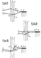
- In Figures from 23 to 27, in which to same elements same reference numerals have been assigned, a further form of practical embodiment of the method according to the present invention can be seen, as applied to the production of fabrics provided with
loops 39 protruding from their surface. In this case, the presence has to be noticed of an element aiming at keeping Lifted theloops 39, which element, in the herein exemplified form of practical embodiment, is ametal blade 34 fastened relative to the weaving plane C by means of a fixedsupport 32. Themetal blade 34 remains inserted inside the fabric for a certain length, and the fabric gets disengaged from theblade 34 during, and thanks to, the movement of the fabric as the production progresses. - The crossing-
thread 4, by getting crossed with themetal blade 34, is obliged to form loop portions, or loops, 39, around it, which loops are of size and shape corresponding to those of the cross-section of themetal blade 34 so that, as the fabric gets disengaged from themetal blade 34, only the loops remain, which loops precisely protrude outwards from the fabric with a stationary-thread 28 being arranged inside them. More precisely, the line segment for keeping portions of the crossing-thread 4 raised, is positioned at at least one portion of the stationary-thread 28 and indicated by thereference numeral 31, and under thethread 4. - In Figures 23 and 23a, the crossing-
thread 4 is in the bottom position of theshed 6, looking at the figure, and is before themetal blade 34 and the stationary-thread 28 positioned above aweft insertion 35. A portion, or line segment, 31 of thestationary thread 28, thanks to the lowered position of aheald 29 and to the simultaneously lifted position of aheald 30, is inclined towards a plane B on the side of theheald 29. The stationary-thread 28 runs through the holes ofsuch healds hole 33 of themetal blade 34 which returns it back to a stable position, parallel to the weaving plane C, alongside of thesame metal blade 34. - In following Figures 24 and 24a, the crossing-
thread 4 has been brought by therespective heald 5 to the top side of theshed 6, while the twohealds thread 28 have inverted their position. The result is that thesegment 31 of thestationary thread 28 comprised between these twohealds thread 28 and of themetal blade 34 alongside of each other; and behind them, looking at the Figures. In fact, in Figures 25 and 25a, after theweft insertion 36 has been carried out, the crossing-thread 4 will be found in its expected position, after precisely passing over the stationary-thread 28 and themetal blade 34, thus forming afurther loop 39. - After a
weft insertion 37, in Figures 26 and 26a, the crossing-thread 4 returns back to its top position, with thehealds thread 28 simultaneously inverting again their position, so that the inclination of thesegment 31 will be now in the suitable direction for a further crossing to be caused to occur between the stationary-thread 28 and the crossing-thread 4. - From Figure 27, which shows a schematic representation of a portion of fabric, adjacent to the weaving zone, obtained according to the just discussed particular form of practical embodiment of the method of the present invention, one may also observe how at a certain point the fabric gets disengaged from the
metal blade 34, and only the stationary-thread 28 remains inside the loops. - The further form of practical embodiment of the same method as proposed by Figures from 28 to 32 demonstrates the flexibility of the method according to the instant invention.
- In fact, by simply getting rid of the last passage of the
warp thread 28 through thehole 33, which in the preceding case was provided in themetal blade 34, in this case a fabric can be obtained which is still provided withloops 39 protruding from its surface, but without any stationary-threads inside the fabric, in that such awarp thread 28 has become now an auxiliary thread which, after being used for constituting theinclined line segment 31 along which the crossing-thread 4 slides, gets tied with the weft insertions externally to the gauze interlacement, therefore without getting crossed with the crossing-thread 4. - Providing again the whole explanation already given for the preceding set of Figures is not necessary here; however, it is worth dwelling for a while on Figure 32, from which one may detect that, from the view point of the strictly-precise textile terminology, it would be inappropriate to speak here of "English-crossing fabric" in order to define the obtained fabric, in that, once that this latter has got disengaged from the
metal blades 34, no stationary elements are any longer present (i.e., neither a stationary-thread, nor a metal blade crossing with the crossing-thread). The weaving method called "gauze weaving" has in fact been used here for the only purpose of creating theloops 39 thanks to the crossing of the crossing-thread 4 which constitutes them, with themetal blade 34 replacing, at least for a certain length inside the fabric, the stationary-thread. - It should be understood however that the herein proposed method does not pose any limitations, not only to the accomplishable interlacement and fabric structure as well as to the system for obtaining the inclined line segments on which the crossing-thread slides, but not even to any further obtainable features.
- Such a method is essentially characterized by the use of one or more line segments which can be alternatively inclined towards the one side, or towards the other side, of the at least one stationary-thread provided, and constituted by lengths of warp threads on whose surface the crossing-thread is caused to slide, thus being alternatively shifted, owing to the effect of such different inclinations, to the one side and to the other side of the same at least one stationary-thread: only thanks to such one or more inclined sliding length(s) the possibility is given of accomplishing the gauze interlacement in all of its possible and imaginable variants, due to the function performed by these lengths, of causing the crossing-thread, according to presettable sequential cycles, to slide to opposite regions of the shed, and to opposite half-weaving planes relatively to the stationary-thread.
- The same at least one inclined sliding length can be accomplished, and/or thought of, in several ways and positions. The essential characteristic thereof is that it should perform the hereinabove illustrated functions in order that the leno or cross weaving texture can be obtained by means of the sliding which said inclined length will cause the crossing-thread to undergo, in order that said crossing-thread is brought to cross with the stationary-thread.
- Finally, the stationary-thread can be accompanied by other warp threads, with each of said threads performing its independent movements in its own shed and perpendicularly to the weaving plane: the crossing-thread will perform its movements getting crossed with this set of warp threads.
Claims (5)
- Method of pro producing a leno or cross weaving texture in which alternatingly with successive weft insertions (13-16;24-27;35-38;40-43), a crossing warp thread (4) crosses at least one "stationary" warp thread (7;17,18;28) alternately from one side of said at least one "stationary" warp thread (7;17,18;28) to its opposite side and viceversa, wherein said crossing warp thread (4) is moved transversally with respect to the plane (C) of the weaving texture and perpendicularly up and down with respect to the plane (C) of the weaving texture, whereas said at least one "stationary" warp thread (7;17,18;28) is movable only perpendicularly up and down with respect to the plane (C) of the weaving texture, said method being characterized in that:- a line segment (10;21,22;31) of said at least one "stationary" warp thread (7;17,18;28) is inclined and is caused to extend, upstream of the beating reed (12, Fig.5) and in the region of the heddles, between two immaginary planes (A,B, Fig.6) parallel to each other and perpendicular to the plane (C) of the weaving texture, one (A) of said two planes lying on one side of said "stationary" thread (7;17,18;28), the other (B) of said two planes lying on the opposite side of said at least one "stationary" thread (7;17,18;28),- said line segment (10;21,22;31) is caused to cross the plane (C) of the weaving texture alternately from a position above the plane (C) of the weaving texture and proximate to said other plane (B) to a position below the plane (C) of the weaving texture and proximate to said one plane (A) and from a position below the plane (C) of the weaving texture and proximate to said other plane (B) to a position above the plane (C) of the weaving texture and proximate to said one plane (A),- said crossing warp thread (4) is caused to slide on said inclined line segment (10;21,22;31) at least when the ends of said inclined line segment (10;21,22;31) cross the plane (C) of the weaving texture, to move respectively first towards the one and then towards the other of the two planes (A,B), thereby crossing said at least one "stationary" warp thread (7;17,18;28) and producing the leno or cross weaving texture.
- Method according to claim 1, characterised by- crossing said crossing warp thread (4) with a pair of said stationary warp threads (17,18),- providing line segments (21,22) of said pair of stationary warp threads (17,18) upstream -of said -beating reed (12), wherein a first line segment (21) connects a common point, in wnich said pair of stationary warp tnreads (17,18) are gathered, to one plane (A) lying on one side of said pair of stationary warp threads (17,18), a second line segment (22) connecting said common point to the other plane (B) lying on the opposite side of said pair of stationary warp tnreads (17, 18),- inclining said first and second line segments (21,22) alternately so as to alternately cause said first line segment (21) to cross the plane (C) of the weaving texture obliquely from a lower side to an upper side of said one plane (A), and cause said second line segment (22) to cross said plane (C) of the weaving texture obliquely from a lower side to an upper side of said other plane (B).- moving said crossing warp thread (4) relative to the inclined line segments (21,22) so that said crossing warp thread (4) is caused to slide alternately along said first line segment (21) toward said one plane (A), and along said second line segment (22) toward said other plane (B), so as to cross said pair of stationary warp threads (17,18).
- Method according to claim 1, characterised in that- loops (39) protruding from the textile interlacement are formed by positioning, at at least one portion of the line segment (31) of the stationary warp thread (28), under it and extending up to reach the interior of the formed leno or cross weaving texture, an element (34) keeping lifted on a plane substantially perpendicular to the plane (C) of the weaving texture, portions of said crossing warp thread (4) which are crossed with said element (34) and with weft insertions (35-38; 40-43), whereby when the fabric gets disengaged from the element (34) during progress of the production of said fabric, said loops (39) remain protruding from the fabric and crossed with said weft insertions (35-38; 40-43).
- Method according to claim 3, characterised in tnat with said portions of said crossing warp thread (4) at least one warp thread (28) is crossed.
- Method according to claim 4, characterised in that a stationary warp thread (28) is used as the warp thread.
Applications Claiming Priority (2)
| Application Number | Priority Date | Filing Date | Title |
|---|---|---|---|
| IT8822624A IT1230646B (en) | 1988-11-15 | 1988-11-15 | METHOD FOR THE REALIZATION OF A GARZA TEXTILE BRAID. |
| IT2262488 | 1988-11-15 |
Publications (2)
| Publication Number | Publication Date |
|---|---|
| EP0369525A1 EP0369525A1 (en) | 1990-05-23 |
| EP0369525B1 true EP0369525B1 (en) | 1997-01-15 |
Family
ID=11198560
Family Applications (1)
| Application Number | Title | Priority Date | Filing Date |
|---|---|---|---|
| EP89202828A Expired - Lifetime EP0369525B1 (en) | 1988-11-15 | 1989-11-08 | Method for producing a leno or cross weaving texture |
Country Status (8)
| Country | Link |
|---|---|
| US (1) | US5085253A (en) |
| EP (1) | EP0369525B1 (en) |
| JP (1) | JPH0762289B2 (en) |
| AT (1) | ATE147802T1 (en) |
| DE (1) | DE68927664T2 (en) |
| ES (1) | ES2096555T3 (en) |
| GR (1) | GR3022602T3 (en) |
| IT (1) | IT1230646B (en) |
Cited By (1)
| Publication number | Priority date | Publication date | Assignee | Title |
|---|---|---|---|---|
| DE10004376A1 (en) * | 2000-02-02 | 2001-08-23 | Dornier Gmbh Lindauer | Process for producing a leno base fabric on weaving machines |
Families Citing this family (5)
| Publication number | Priority date | Publication date | Assignee | Title |
|---|---|---|---|---|
| GB9814971D0 (en) * | 1998-07-11 | 1998-09-09 | Griffith Textile Mach Ltd | Leno weaving |
| GB2426253B (en) * | 2005-05-20 | 2009-11-25 | Griffith Textile Mach Ltd | Apparatus and a method for weaving leno fabric |
| US10161067B2 (en) * | 2012-03-01 | 2018-12-25 | Groz-Beckert Kg | Fabric for use in composite materials and method for producing said fabric and a composite material body |
| BE1022146B1 (en) * | 2014-06-13 | 2016-02-19 | Picanol | SELF-EDUCATION DEVICE FOR A WRAKING THREAD |
| US10905188B2 (en) * | 2016-07-19 | 2021-02-02 | Bradford C. Jamison | Plexus of filaments with linked members |
Family Cites Families (8)
| Publication number | Priority date | Publication date | Assignee | Title |
|---|---|---|---|---|
| DE42013C (en) * | L. RICHTER in Berlin SO., Gräfestrafse 82 I | Loom for gauze weave | ||
| US1416410A (en) * | 1921-11-03 | 1922-05-16 | Draper Corp | Leno or cross-weaving loom |
| US2187540A (en) * | 1937-11-05 | 1940-01-16 | Boller Winkler & Co | Manufacture of full-cross gauze fabrics |
| US2278862A (en) * | 1941-06-25 | 1942-04-07 | Octave P Caron | Loom |
| US2389258A (en) * | 1944-07-08 | 1945-11-20 | Steel Heddle Mfg Co | Harness for cross-weaving |
| US2647541A (en) * | 1951-02-17 | 1953-08-04 | Draper Corp | Leno weaving |
| JPH0243902Y2 (en) * | 1985-12-05 | 1990-11-21 | ||
| IT1197783B (en) * | 1986-07-18 | 1988-12-06 | Carmelo Motta | SIMPLIFIED METHOD FOR THE REALIZATION OF A TEXTILE BRAID OF THE TYPE NAMED AS A GAUZE |
-
1988
- 1988-11-15 IT IT8822624A patent/IT1230646B/en active
-
1989
- 1989-11-08 AT AT89202828T patent/ATE147802T1/en not_active IP Right Cessation
- 1989-11-08 EP EP89202828A patent/EP0369525B1/en not_active Expired - Lifetime
- 1989-11-08 ES ES89202828T patent/ES2096555T3/en not_active Expired - Lifetime
- 1989-11-08 DE DE68927664T patent/DE68927664T2/en not_active Expired - Lifetime
- 1989-11-09 US US07/433,791 patent/US5085253A/en not_active Expired - Lifetime
- 1989-11-15 JP JP1295166A patent/JPH0762289B2/en not_active Expired - Fee Related
-
1997
- 1997-02-19 GR GR970400287T patent/GR3022602T3/en unknown
Cited By (1)
| Publication number | Priority date | Publication date | Assignee | Title |
|---|---|---|---|---|
| DE10004376A1 (en) * | 2000-02-02 | 2001-08-23 | Dornier Gmbh Lindauer | Process for producing a leno base fabric on weaving machines |
Also Published As
| Publication number | Publication date |
|---|---|
| ES2096555T3 (en) | 1997-03-16 |
| ATE147802T1 (en) | 1997-02-15 |
| JPH02210040A (en) | 1990-08-21 |
| US5085253A (en) | 1992-02-04 |
| DE68927664T2 (en) | 1997-07-31 |
| EP0369525A1 (en) | 1990-05-23 |
| JPH0762289B2 (en) | 1995-07-05 |
| IT1230646B (en) | 1991-10-28 |
| DE68927664D1 (en) | 1997-02-27 |
| IT8822624A0 (en) | 1988-11-15 |
| GR3022602T3 (en) | 1997-05-31 |
Similar Documents
| Publication | Publication Date | Title |
|---|---|---|
| CA2263202A1 (en) | A device for controlling warp threads for the production of leno fabrics on a textile machine | |
| CN108541280A (en) | The method of fabric, especially carpet and braided fabric | |
| EP0369525B1 (en) | Method for producing a leno or cross weaving texture | |
| US3746051A (en) | Machine for making a partly woven and partly knitted fabric | |
| RU2037577C1 (en) | Bulked cloth and method and device for its manufacture | |
| US3499471A (en) | Method of weaving velvet tapes and the like | |
| US4406309A (en) | Method and apparatus for forming a woven pile fabric | |
| US4463782A (en) | Shedding apparatus for circular weaving of multi-harness fabrics and method of using the apparatus | |
| US2955619A (en) | Loom selvage motion | |
| US3580295A (en) | Partly woven and partly knitted fabric and apparatus for making the same | |
| JPS6375138A (en) | Simplified method for achieving interlacing of so called gauze type fiber | |
| PT86103A (en) | CIRCULAR AUTOMATIC TEAR | |
| US2141409A (en) | Lace fabric | |
| US3879964A (en) | Method and apparatus for making a novel fabric | |
| US3256913A (en) | Crossing formation on fabrics | |
| US3636988A (en) | Apparatus and method for weaving fabric with intricate pile formations | |
| US4579151A (en) | Machine for making a partly woven partly knitted fabric | |
| SU942736A1 (en) | Blood vessel multichannel prosthesis | |
| SU1101482A1 (en) | Method of forming cloth in loom | |
| US2073494A (en) | Method of and means for producing textile fabrics | |
| JPH0860490A (en) | Bead-weaving machine with curved needle | |
| US795353A (en) | Loom for weaving looped and cut pile fabrics. | |
| US3884054A (en) | Knit fabric incorporating a warp stitch weave | |
| US764208A (en) | Woven lace fabric. | |
| US1992862A (en) | Pile fabric and method of and apparatus for weaving the same |
Legal Events
| Date | Code | Title | Description |
|---|---|---|---|
| PUAI | Public reference made under article 153(3) epc to a published international application that has entered the european phase |
Free format text: ORIGINAL CODE: 0009012 |
|
| AK | Designated contracting states |
Kind code of ref document: A1 Designated state(s): AT BE CH DE ES FR GB GR LI LU NL SE |
|
| RAP1 | Party data changed (applicant data changed or rights of an application transferred) |
Owner name: YOSHIDA KOGYO K.K. |
|
| RIN1 | Information on inventor provided before grant (corrected) |
Inventor name: MOTTA,CARMELO |
|
| 17P | Request for examination filed |
Effective date: 19901017 |
|
| 17Q | First examination report despatched |
Effective date: 19920721 |
|
| RAP1 | Party data changed (applicant data changed or rights of an application transferred) |
Owner name: YKK CORPORATION |
|
| GRAH | Despatch of communication of intention to grant a patent |
Free format text: ORIGINAL CODE: EPIDOS IGRA |
|
| GRAH | Despatch of communication of intention to grant a patent |
Free format text: ORIGINAL CODE: EPIDOS IGRA |
|
| GRAA | (expected) grant |
Free format text: ORIGINAL CODE: 0009210 |
|
| AK | Designated contracting states |
Kind code of ref document: B1 Designated state(s): AT BE CH DE ES FR GB GR LI LU NL SE |
|
| REF | Corresponds to: |
Ref document number: 147802 Country of ref document: AT Date of ref document: 19970215 Kind code of ref document: T |
|
| REG | Reference to a national code |
Ref country code: CH Ref legal event code: EP |
|
| REF | Corresponds to: |
Ref document number: 68927664 Country of ref document: DE Date of ref document: 19970227 |
|
| REG | Reference to a national code |
Ref country code: CH Ref legal event code: NV Representative=s name: AMMANN PATENTANWAELTE AG BERN |
|
| REG | Reference to a national code |
Ref country code: ES Ref legal event code: FG2A Ref document number: 2096555 Country of ref document: ES Kind code of ref document: T3 |
|
| ET | Fr: translation filed | ||
| REG | Reference to a national code |
Ref country code: GR Ref legal event code: FG4A Free format text: 3022602 |
|
| PLBE | No opposition filed within time limit |
Free format text: ORIGINAL CODE: 0009261 |
|
| STAA | Information on the status of an ep patent application or granted ep patent |
Free format text: STATUS: NO OPPOSITION FILED WITHIN TIME LIMIT |
|
| 26N | No opposition filed | ||
| REG | Reference to a national code |
Ref country code: GB Ref legal event code: IF02 |
|
| PGFP | Annual fee paid to national office [announced via postgrant information from national office to epo] |
Ref country code: NL Payment date: 20081116 Year of fee payment: 20 Ref country code: LU Payment date: 20081119 Year of fee payment: 20 Ref country code: CH Payment date: 20081117 Year of fee payment: 20 Ref country code: DE Payment date: 20081107 Year of fee payment: 20 |
|
| PGFP | Annual fee paid to national office [announced via postgrant information from national office to epo] |
Ref country code: ES Payment date: 20081127 Year of fee payment: 20 Ref country code: AT Payment date: 20081112 Year of fee payment: 20 |
|
| PGFP | Annual fee paid to national office [announced via postgrant information from national office to epo] |
Ref country code: SE Payment date: 20081107 Year of fee payment: 20 Ref country code: BE Payment date: 20081016 Year of fee payment: 20 |
|
| PGFP | Annual fee paid to national office [announced via postgrant information from national office to epo] |
Ref country code: FR Payment date: 20081112 Year of fee payment: 20 |
|
| PGFP | Annual fee paid to national office [announced via postgrant information from national office to epo] |
Ref country code: GB Payment date: 20081105 Year of fee payment: 20 Ref country code: GR Payment date: 20081017 Year of fee payment: 20 |
|
| REG | Reference to a national code |
Ref country code: CH Ref legal event code: PL |
|
| BE20 | Be: patent expired |
Owner name: *YKK CORP. Effective date: 20091108 |
|
| REG | Reference to a national code |
Ref country code: GB Ref legal event code: PE20 Expiry date: 20091107 |
|
| NLV7 | Nl: ceased due to reaching the maximum lifetime of a patent |
Effective date: 20091108 |
|
| REG | Reference to a national code |
Ref country code: ES Ref legal event code: FD2A Effective date: 20091109 |
|
| PG25 | Lapsed in a contracting state [announced via postgrant information from national office to epo] |
Ref country code: NL Free format text: LAPSE BECAUSE OF EXPIRATION OF PROTECTION Effective date: 20091108 |
|
| PG25 | Lapsed in a contracting state [announced via postgrant information from national office to epo] |
Ref country code: GB Free format text: LAPSE BECAUSE OF EXPIRATION OF PROTECTION Effective date: 20091107 Ref country code: ES Free format text: LAPSE BECAUSE OF EXPIRATION OF PROTECTION Effective date: 20091109 |