EP0368709A2 - Werbetafel mit metallischen Komponenten - Google Patents
Werbetafel mit metallischen Komponenten Download PDFInfo
- Publication number
- EP0368709A2 EP0368709A2 EP89402887A EP89402887A EP0368709A2 EP 0368709 A2 EP0368709 A2 EP 0368709A2 EP 89402887 A EP89402887 A EP 89402887A EP 89402887 A EP89402887 A EP 89402887A EP 0368709 A2 EP0368709 A2 EP 0368709A2
- Authority
- EP
- European Patent Office
- Prior art keywords
- fixed
- display panel
- candle
- panel according
- fixing
- Prior art date
- Legal status (The legal status is an assumption and is not a legal conclusion. Google has not performed a legal analysis and makes no representation as to the accuracy of the status listed.)
- Granted
Links
Images


Classifications
-
- G—PHYSICS
- G09—EDUCATION; CRYPTOGRAPHY; DISPLAY; ADVERTISING; SEALS
- G09F—DISPLAYING; ADVERTISING; SIGNS; LABELS OR NAME-PLATES; SEALS
- G09F15/00—Boards, hoardings, pillars, or like structures for notices, placards, posters, or the like
- G09F15/0006—Boards, hoardings, pillars, or like structures for notices, placards, posters, or the like planar structures comprising one or more panels
Definitions
- the invention relates to display panels, and more particularly to display panels with metallic components, of the type comprising a foot made up of at least one substantially vertical post and a framework provided with at least one substantially horizontal beam.
- Display panels are already known, for example for advertising display, the framework of which, consisting of posts and beams and / or crossbeams connected together by bolting, is essentially of steel having undergone a protective treatment such than galvanizing, and comprising mechanically welded parts.
- the thickness of these panels is important, which affects the aesthetics of the assembly.
- the object of the invention is to remedy these drawbacks and to this end relates to a display panel with metallic elements, of the type comprising a foot consisting of at least one substantially vertical post and a frame provided with at least one substantially beam horizontal, panel characterized in that the beam is arranged above the foot, on the latter, and is fixed to each post by means of a fixing member comprising on the one hand a split collar provided with parallel clamping lugs and enclosing said beam and on the other hand an end piece fitted in said post, in that the framework also comprises at least one strut and at least one cross member arranged above the beam thereon, each strut being fixed to the beam by means of another similar fixing member, the split collar of which surrounds said beam and the end piece is fitted into said strut, and in that said cross member is placed and fixed on at least one support member itself disposed on the collar and threaded around said strut.
- the overall dimensions can be considerably reduced (60% gain in thickness), in particular because the horizontal beams and crosspieces are fixed in the plane of the candles; the same is true of the weight, because according to an advantageous characteristic of the invention, the least load-bearing parts are molded from metal or light alloy and adapt to the posts with a minimum of bulk.
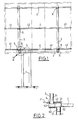
- the panel shown in Figure 1 has a foot and a supporting frame for the display surface.
- the base consists of one or more posts (x), here two posts 1, substantially vertical, tubular and of square section (inside and outside).
- the framework consists of a substantially horizontal beam 2, also of square external section, substantially vertical candles 3, also tubular and of generally square section inside and out, and crosspieces 4 parallel to beam 2.
- all of these components are arranged in the plane of the base so that the overall thickness of the panel is very small.
- the beam 2 is arranged above and on the upper end of the posts 1. Its fixing is carried out by means of fixing members 5 comprising a nozzle 51 and a split collar 52, in a single part or made up of two welded, brazed or similar parts.
- the end pieces 51 are mounted by interlocking in the ends of the posts 1 and provided with fixing holes to these posts, possibly tapped for the purpose of fixing by screws or bolts passing through the posts.
- the collars 52 which also internally have a square shape, are slidably mounted around the beam 2 due to their corresponding dimensions and to the fact that they are split; they are provided, opposite the end piece 51, with two clamping lugs 53 formed by L-shaped irons (also in one piece, or welded, or brazed, or the like) extending longitudinally, parallel to the central axis of the collar; the legs 53, parallel and spaced from each other have holes 54 opposite for fixing the beam by screwing or bolting, this fixing being obtained by tightening the collar around the beam thanks to the spacing of the paws ; the length of the legs is greater than that of the collar on one side thereof, and the legs have an additional hole 55 whose axis is at the right of this end; on the end of the end piece, the collar is provided with another tab 56, facing the space between the clamping tabs 53, arranged parallel to these and also comprising a hole 57 whose axis is at right from the same end of the collar.
- the lower end of the candles 3 is itself disposed above and on the beam 2, and the fixing of the candles 3 to the beam 2 is carried out by means of fixing members 5 similar to those which have already been described, and even preferably identical.
- fixing members 5 similar to those which have already been described, and even preferably identical.
- the head-to-tail arrangement of the members for fixing the beam 2 to a post 1, and a candle 3 to the beam 2 allows, if the fixing members 5 are arranged one against the other and oriented so appropriate, insert the additional tab 56 end end of each fixing member, between the clamping legs 53 of the fixing member which faces them; if the collars 52 of the two fixing members are in contact, the holes 55, 57 of the three tabs 53, 56 are facing each other, and, tip end as opposite side, it is possible to fix the two to each other fasteners 5, by bolting or screwing.
- the cross section of the posts 1 must be greater than that of the candles 3, a fur must be inserted in the posts, between the internal wall of the latter and the wall outer end pieces 51. It is possible to choose the dimensions of the beam 2 so that a section of the profile which constitutes it is used as furring, that is to say that its inner section has the same dimensions as the outer section of the end piece, and that its outer section has the same dimensions as the inner section of the post.
- the crosspieces 4 can be, as here, in several elements 41, 42, 43 arranged on either side of the candles 3, or in a single element comprising openings for the passage of these candles and threaded around them; the elements 41, 42, 43 forming the crosspieces 4 are installed and fixed on a support member 6 itself disposed on the collar 52 and threaded around the candle.
- This support member 6 includes a vertical well 61 for fixing to the upright on either side of which extend horizontally two plates 62 for fixing the cross members.
- the well 61 the internal shape of which corresponds to a slight clearance close to the external shape of the candle 3, is threaded around the corresponding candle until it rests on the beam 2 or more exactly on the upper part of the member.
- fixing 5 of the candle; the two fixing plates 62 are identical and arranged symmetrically, except for the fact that one is slightly less wide than the other (both have a width slightly less than that of the well 61).
- the well 61 consists of four ribs extending substantially vertically and parallel two by two; the two ribs 63 joining one plate to the other have a lower height above the plates than those 64 which are perpendicular to them, but the four ribs 63, 64 arrive at the same level below the plates 62; the last two ribs 64 mentioned have a general trapezoidal shape and comprise, at their upper part, a hole 65 for attachment to the candles, intended to come opposite a hole provided in them for fixing by screwing or bolting; the plates 62 themselves have fixing holes 66 for the crossmember or the crossmember elements, these holes being arranged on either side of an axial slot 67 intended to allow access to the screws or bolts for tightening the collars arranged below, and provided with a countersink 68 for guiding the heads of the screws for fixing the crosspieces; stiffening ribs 69 extend under the plates, from the free end thereof, and arrive at the right of the free end of the well 61, so as to prevent the bending of
- the internal-external sleeving device 5 which has been described, using identical molded parts, made of special impact-resistant cast iron, slidingly mounted (before fixing) on a beam 2 made of very high-performance light alloy, and penetrating inside. candles 3 and posts 1, allows to combine the advantages of a high standardization and good robustness due to a direct transmission of forces with correct continuity candles-posts.
- the two posts 1 made of steel, a resistant but heavy metal, serve as a support base for the assembly, but the removal of their unnecessarily robust upper part allows substantial savings in weight; advantageously, the weight of the display surface which is transmitted to the frame and more particularly to the part of this formed by the crosspieces 4 (for example in U-shaped steel section) and from there by candles (tubular in light alloy), is taken up by the horizontal beam, which can also be in light alloy, and the mounting of which sliding before tightening allows adjustment of the position of the panel relative to the foot.
- the fixing members 5 are made of cast iron
- the support members 6 are made of light alloy (hardened and tempered), which further minimizes the weight of the frame.
- This assembly is carried out in the following order: firstly by fitting the end pieces 51 of the fixing members 5 in the posts 1, and secondly by threading the support members 6 around the candles 3, then the beam 2 is threaded into the collars 52 of the fixing members 5, the beam 2 is adjusted, the candles 3 are fitted, the set of screws or / and bolts is tightened (in number much weaker than according to the prior art thanks to the wide use of foundry parts), and finally the crossmembers 4 are mounted and fixed on the support members 6.
Landscapes
- Physics & Mathematics (AREA)
- General Physics & Mathematics (AREA)
- Engineering & Computer Science (AREA)
- Theoretical Computer Science (AREA)
- Connection Of Plates (AREA)
- Adornments (AREA)
- Illuminated Signs And Luminous Advertising (AREA)
Applications Claiming Priority (2)
| Application Number | Priority Date | Filing Date | Title |
|---|---|---|---|
| FR8813740 | 1988-10-19 | ||
| FR8813740A FR2638008B1 (fr) | 1988-10-19 | 1988-10-19 | Panneau d'affichage a composants metalliques |
Publications (3)
| Publication Number | Publication Date |
|---|---|
| EP0368709A2 true EP0368709A2 (de) | 1990-05-16 |
| EP0368709A3 EP0368709A3 (de) | 1991-05-22 |
| EP0368709B1 EP0368709B1 (de) | 1995-02-08 |
Family
ID=9371156
Family Applications (1)
| Application Number | Title | Priority Date | Filing Date |
|---|---|---|---|
| EP19890402887 Expired - Lifetime EP0368709B1 (de) | 1988-10-19 | 1989-10-19 | Werbetafel mit metallischen Komponenten |
Country Status (4)
| Country | Link |
|---|---|
| EP (1) | EP0368709B1 (de) |
| DE (1) | DE68921039T2 (de) |
| ES (1) | ES2070922T3 (de) |
| FR (1) | FR2638008B1 (de) |
Families Citing this family (1)
| Publication number | Priority date | Publication date | Assignee | Title |
|---|---|---|---|---|
| CN2828994Y (zh) * | 2005-08-22 | 2006-10-18 | 王德海 | 用于矗立的悬浮式展示系统 |
Citations (6)
| Publication number | Priority date | Publication date | Assignee | Title |
|---|---|---|---|---|
| FR1080231A (fr) * | 1953-06-30 | 1954-12-07 | Henry Hartley & Company Ltd | Raccord ou bouchon pour tubes |
| US2901849A (en) * | 1956-08-09 | 1959-09-01 | Butler Manufacturing Co | Advertising panel |
| US3010234A (en) * | 1960-09-29 | 1961-11-28 | Pacific Outdoor Advertising Co | Supported vertical display panels |
| US3150455A (en) * | 1961-02-27 | 1964-09-29 | Donald L Indorf | Sheet increment sign assembly |
| FR2319797A1 (fr) * | 1975-07-30 | 1977-02-25 | Pecheux Jean Claude | Raccord pour structures tubulaires demontables |
| EP0053860A1 (de) * | 1980-12-04 | 1982-06-16 | Cenclark B.V. | Brüstung für Gerüste |
-
1988
- 1988-10-19 FR FR8813740A patent/FR2638008B1/fr not_active Expired - Fee Related
-
1989
- 1989-10-19 DE DE1989621039 patent/DE68921039T2/de not_active Expired - Fee Related
- 1989-10-19 ES ES89402887T patent/ES2070922T3/es not_active Expired - Lifetime
- 1989-10-19 EP EP19890402887 patent/EP0368709B1/de not_active Expired - Lifetime
Patent Citations (6)
| Publication number | Priority date | Publication date | Assignee | Title |
|---|---|---|---|---|
| FR1080231A (fr) * | 1953-06-30 | 1954-12-07 | Henry Hartley & Company Ltd | Raccord ou bouchon pour tubes |
| US2901849A (en) * | 1956-08-09 | 1959-09-01 | Butler Manufacturing Co | Advertising panel |
| US3010234A (en) * | 1960-09-29 | 1961-11-28 | Pacific Outdoor Advertising Co | Supported vertical display panels |
| US3150455A (en) * | 1961-02-27 | 1964-09-29 | Donald L Indorf | Sheet increment sign assembly |
| FR2319797A1 (fr) * | 1975-07-30 | 1977-02-25 | Pecheux Jean Claude | Raccord pour structures tubulaires demontables |
| EP0053860A1 (de) * | 1980-12-04 | 1982-06-16 | Cenclark B.V. | Brüstung für Gerüste |
Also Published As
| Publication number | Publication date |
|---|---|
| FR2638008A1 (fr) | 1990-04-20 |
| ES2070922T3 (es) | 1995-06-16 |
| DE68921039T2 (de) | 1995-06-01 |
| EP0368709A3 (de) | 1991-05-22 |
| DE68921039D1 (de) | 1995-03-23 |
| EP0368709B1 (de) | 1995-02-08 |
| FR2638008B1 (fr) | 1993-01-08 |
Similar Documents
| Publication | Publication Date | Title |
|---|---|---|
| FR2660708A1 (fr) | Piece d'assemblage pour elements longiformes. | |
| FR2552174A1 (fr) | Dispositif de fixation reglable pour plaques de parement | |
| FR2537906A1 (fr) | Ratelier a consoles | |
| EP0368709B1 (de) | Werbetafel mit metallischen Komponenten | |
| FR2458640A1 (fr) | Faux-plafond metallique | |
| EP0088363B1 (de) | Vorrichtung zur Aufhängung von Rohrbündeln | |
| EP0347388A1 (de) | Modulare, verlaufsveränderliche Absperrung zum Bilden einer Schutzumfriedung | |
| WO2009103882A1 (fr) | Socle antivibratile multi-format | |
| EP0462039B1 (de) | Modulartige Spielvorrichtung | |
| EP0702589B1 (de) | Vorrichtung zum befestigen von zwei gebogenen barren an einen horizontalen barren | |
| CH651087A5 (fr) | Element d'ossature de support pour plaques ou grilles de couverture et plaque ou grille de couverture correspondante. | |
| FR2495884A1 (fr) | Dispositif de reception d'au moins une plaquette, notamment de circuit imprime, et utilisation d'un tel dispositif | |
| BE1008102A6 (fr) | Moule pour la fabrication d'elements en beton. | |
| FR2678515A1 (fr) | Dispositif de fixation de panneaux artificiels d'escalade. | |
| EP0055158B1 (de) | Mindestens zwei Langstab-Isolatorenketten umfassende Sicherheitsverbindungsvorrichtung für elektrische Freileitungen | |
| EP0014623A1 (de) | Versteifungselement für Baugerüste | |
| EP1908897B1 (de) | Zaunanlage | |
| FR2791756A1 (fr) | Element de grille metallique, notamment pour cloture, et grille, vantail de portail ou portillon comprenant un tel element de grille | |
| FR2820769A1 (fr) | Panneau garde-corps de securite | |
| FR2891125A1 (fr) | Caillebotis | |
| FR2554693A1 (fr) | Rayonnage a ossature metallique | |
| FR2714451A1 (fr) | Système de protection pour machine ou équivalent comportant des panneaux de protection grillagés. | |
| BE1022263B1 (fr) | Batiment a ossature en bois | |
| FR2746432A1 (fr) | Dispositif de support pour un agencement formant plancher sur des parois peripheriques d'une structure | |
| FR2831456A1 (fr) | Plaque de support pour element de retenue d'une chaussure sur une planche de glisse |
Legal Events
| Date | Code | Title | Description |
|---|---|---|---|
| PUAI | Public reference made under article 153(3) epc to a published international application that has entered the european phase |
Free format text: ORIGINAL CODE: 0009012 |
|
| AK | Designated contracting states |
Kind code of ref document: A2 Designated state(s): BE DE ES GB IT NL |
|
| PUAL | Search report despatched |
Free format text: ORIGINAL CODE: 0009013 |
|
| AK | Designated contracting states |
Kind code of ref document: A3 Designated state(s): BE DE ES GB IT NL |
|
| 17P | Request for examination filed |
Effective date: 19910829 |
|
| 17Q | First examination report despatched |
Effective date: 19930621 |
|
| GRAA | (expected) grant |
Free format text: ORIGINAL CODE: 0009210 |
|
| AK | Designated contracting states |
Kind code of ref document: B1 Designated state(s): BE DE ES GB IT NL |
|
| ITF | It: translation for a ep patent filed |
Owner name: JACOBACCI CASETTA & PERANI S.P.A. |
|
| REF | Corresponds to: |
Ref document number: 68921039 Country of ref document: DE Date of ref document: 19950323 |
|
| GBT | Gb: translation of ep patent filed (gb section 77(6)(a)/1977) |
Effective date: 19950406 |
|
| REG | Reference to a national code |
Ref country code: ES Ref legal event code: FG2A Ref document number: 2070922 Country of ref document: ES Kind code of ref document: T3 |
|
| PGFP | Annual fee paid to national office [announced via postgrant information from national office to epo] |
Ref country code: ES Payment date: 19951003 Year of fee payment: 7 |
|
| PGFP | Annual fee paid to national office [announced via postgrant information from national office to epo] |
Ref country code: NL Payment date: 19951020 Year of fee payment: 7 |
|
| PLBE | No opposition filed within time limit |
Free format text: ORIGINAL CODE: 0009261 |
|
| STAA | Information on the status of an ep patent application or granted ep patent |
Free format text: STATUS: NO OPPOSITION FILED WITHIN TIME LIMIT |
|
| 26N | No opposition filed | ||
| PG25 | Lapsed in a contracting state [announced via postgrant information from national office to epo] |
Ref country code: ES Free format text: LAPSE BECAUSE OF EXPIRATION OF PROTECTION Effective date: 19961021 |
|
| PG25 | Lapsed in a contracting state [announced via postgrant information from national office to epo] |
Ref country code: NL Effective date: 19970501 |
|
| NLV4 | Nl: lapsed or anulled due to non-payment of the annual fee |
Effective date: 19970501 |
|
| PGFP | Annual fee paid to national office [announced via postgrant information from national office to epo] |
Ref country code: BE Payment date: 19981009 Year of fee payment: 10 |
|
| PGFP | Annual fee paid to national office [announced via postgrant information from national office to epo] |
Ref country code: DE Payment date: 19981016 Year of fee payment: 10 |
|
| PGFP | Annual fee paid to national office [announced via postgrant information from national office to epo] |
Ref country code: GB Payment date: 19981023 Year of fee payment: 10 |
|
| REG | Reference to a national code |
Ref country code: ES Ref legal event code: FD2A Effective date: 19990601 |
|
| PG25 | Lapsed in a contracting state [announced via postgrant information from national office to epo] |
Ref country code: GB Free format text: LAPSE BECAUSE OF NON-PAYMENT OF DUE FEES Effective date: 19991019 |
|
| PG25 | Lapsed in a contracting state [announced via postgrant information from national office to epo] |
Ref country code: BE Free format text: LAPSE BECAUSE OF NON-PAYMENT OF DUE FEES Effective date: 19991031 |
|
| BERE | Be: lapsed |
Owner name: S.A. FORNELLS Effective date: 19991031 |
|
| GBPC | Gb: european patent ceased through non-payment of renewal fee |
Effective date: 19991019 |
|
| PG25 | Lapsed in a contracting state [announced via postgrant information from national office to epo] |
Ref country code: DE Free format text: LAPSE BECAUSE OF NON-PAYMENT OF DUE FEES Effective date: 20000801 |
|
| PG25 | Lapsed in a contracting state [announced via postgrant information from national office to epo] |
Ref country code: IT Free format text: LAPSE BECAUSE OF NON-PAYMENT OF DUE FEES;WARNING: LAPSES OF ITALIAN PATENTS WITH EFFECTIVE DATE BEFORE 2007 MAY HAVE OCCURRED AT ANY TIME BEFORE 2007. THE CORRECT EFFECTIVE DATE MAY BE DIFFERENT FROM THE ONE RECORDED. Effective date: 20051019 |