EP0368554A2 - Verdrillt-nematische Flüssigkristall-Anzeigevorrichtung - Google Patents
Verdrillt-nematische Flüssigkristall-Anzeigevorrichtung Download PDFInfo
- Publication number
- EP0368554A2 EP0368554A2 EP89311326A EP89311326A EP0368554A2 EP 0368554 A2 EP0368554 A2 EP 0368554A2 EP 89311326 A EP89311326 A EP 89311326A EP 89311326 A EP89311326 A EP 89311326A EP 0368554 A2 EP0368554 A2 EP 0368554A2
- Authority
- EP
- European Patent Office
- Prior art keywords
- liquid crystal
- degrees
- crystal layer
- polarizing plate
- display device
- Prior art date
- Legal status (The legal status is an assumption and is not a legal conclusion. Google has not performed a legal analysis and makes no representation as to the accuracy of the status listed.)
- Granted
Links
Images


Classifications
-
- G—PHYSICS
- G02—OPTICS
- G02F—OPTICAL DEVICES OR ARRANGEMENTS FOR THE CONTROL OF LIGHT BY MODIFICATION OF THE OPTICAL PROPERTIES OF THE MEDIA OF THE ELEMENTS INVOLVED THEREIN; NON-LINEAR OPTICS; FREQUENCY-CHANGING OF LIGHT; OPTICAL LOGIC ELEMENTS; OPTICAL ANALOGUE/DIGITAL CONVERTERS
- G02F1/00—Devices or arrangements for the control of the intensity, colour, phase, polarisation or direction of light arriving from an independent light source, e.g. switching, gating or modulating; Non-linear optics
- G02F1/01—Devices or arrangements for the control of the intensity, colour, phase, polarisation or direction of light arriving from an independent light source, e.g. switching, gating or modulating; Non-linear optics for the control of the intensity, phase, polarisation or colour
- G02F1/13—Devices or arrangements for the control of the intensity, colour, phase, polarisation or direction of light arriving from an independent light source, e.g. switching, gating or modulating; Non-linear optics for the control of the intensity, phase, polarisation or colour based on liquid crystals, e.g. single liquid crystal display cells
- G02F1/137—Devices or arrangements for the control of the intensity, colour, phase, polarisation or direction of light arriving from an independent light source, e.g. switching, gating or modulating; Non-linear optics for the control of the intensity, phase, polarisation or colour based on liquid crystals, e.g. single liquid crystal display cells characterised by the electro-optical or magneto-optical effect, e.g. field-induced phase transition, orientation effect, guest-host interaction or dynamic scattering
- G02F1/139—Devices or arrangements for the control of the intensity, colour, phase, polarisation or direction of light arriving from an independent light source, e.g. switching, gating or modulating; Non-linear optics for the control of the intensity, phase, polarisation or colour based on liquid crystals, e.g. single liquid crystal display cells characterised by the electro-optical or magneto-optical effect, e.g. field-induced phase transition, orientation effect, guest-host interaction or dynamic scattering based on orientation effects in which the liquid crystal remains transparent
- G02F1/1396—Devices or arrangements for the control of the intensity, colour, phase, polarisation or direction of light arriving from an independent light source, e.g. switching, gating or modulating; Non-linear optics for the control of the intensity, phase, polarisation or colour based on liquid crystals, e.g. single liquid crystal display cells characterised by the electro-optical or magneto-optical effect, e.g. field-induced phase transition, orientation effect, guest-host interaction or dynamic scattering based on orientation effects in which the liquid crystal remains transparent the liquid crystal being selectively controlled between a twisted state and a non-twisted state, e.g. TN-LC cell
Definitions
- the present invention relates to a so-called "normally black" type twisted nematic liquid crystal display device in which a liquid crystal is subjected to twisted orientation by 90° so that, when a voltage is not applied to the liquid crystal, light is not able to pass through it.
- a liquid crystal layer In a "normally black" type twisted nematic liquid crystal display device, a liquid crystal layer, the major axes of the molecules of which are subjected to twisted orientation by 90°, is placed between a first transparent electrode subjected to orientation treatment in a first direction and a second transparent electrode subjected to orientation treatment in a second direction perpendicular to the first direction.
- a first transparent polarizing plate having a direction of polarization coinciding with the first direction is provided outside the first electrode and a second transparent polarizing plate also having a direction of polarization coinciding with the first direction is provided outside the second electrode.
- the optical path length difference (i.e. retardation) ⁇ nd of the liquid crystal layer that is, the product of the thickness d of the liquid crystal layer between the first and second electrodes (i.e. the thickness of the layer) and the double refraction index ⁇ n of the liquid crystal layer
- ⁇ nd of the liquid crystal layer that is, the product of the thickness d of the liquid crystal layer between the first and second electrodes (i.e. the thickness of the layer) and the double refraction index ⁇ n of the liquid crystal layer
- the second polarizing plate is viewed. This is normally not transmitting any light.
- Japanese Published Unexamined Patent Application No. 62-180327 discloses a liquid crystal display panel in which the difference in the optical path length of its liquid crystal layer is made to be in a range from 0.7 ⁇ m to 0.9 ⁇ m and the difference in between the polarizing angle due to the polarizing plate and the rubbing angle is made to be in the range from 20° to 50°.
- Japanese Published Unexamined Patent Application No. 62-240928 discloses a liquid crystal optical shutter in which the product of the thickness of its liquid crystal layer and the double refraction index of the liquid crystal layer is made to be not smaller than 0.18 ⁇ m and not larger than 0.4 ⁇ m.
- the contrast ratio can be made a maximum when the display screen utilizing the device is observed from the front face, but the black level (colour of background) and the contrast ratio vary with the change in the visual angle.
- the liquid crystal layer must be made thin. Accordingly, even if small errors exist in the thickness of the layer, the contrast and the chromaticity will vary.
- the technology disclosed in Japanese Published Unexamined Patent Application No. 62-180327 is applicable only to the so-called simple matrix-type liquid crystal display devices.
- the technology relates to a TN type liquid crystal display device using a bias rubbing method in which the twist of the axes of the molecules of its liquid crystal layer is not necessarily 90°, and the technology is not applicable to a "normally black" mode type twisted nematic liquid crystal display device.
- the technology described in Japanese Published Unexamined Patent Application No. 62-240928 is one for enhancing the optical response speed of a liquid crystal shutter, and it is not applicable to a liquid crystal display device having a large screen.
- the thickness of the liquid crystal layer that is, the thickness d of the cell to be 1.8 ⁇ m to 4 ⁇ m if the double refraction index ⁇ n of the liquid crystal layer is 0.1. It is technically difficult to realize this thickness ranging over a large area, for example, in a range where errors must be within ⁇ 0.2 ⁇ m.
- the object of the present invention is to provide a "normally black" type twisted nematic liquid crystal display device in which, when the visual angle is varied, the variation in its contrast and black level (colour of background) is relatively small, the variation in its contrast and colour is relatively small for a very small variation in the thickness of the liquid crystal layer, that is, the thickness of the cell, and, moreover, a sufficient contrast can be obtained.
- the present invention relates to a twisted nematic liquid crystal display device comprising a first transparent electrode which has been subjected to orientation treatment in a first direction, a second transparent electrode which has been subjected to orientation treatment in a second direction, a liquid crystal layer, the major axes of the molecules of which have been subjected to twisted orientation by 90°, located between said first and second electrodes, a first transparent polarizing plate having a direction of polarization coinciding with the first direction and located outside the first electrode, and a second transparent polarizing plate having a direction of polarization coinciding with the second direction and located outside the second electrode.
- the display device is characterised in that the optical path length difference ( ⁇ nd) of the liquid crystal layer, which is equal to the product of the thickness (d) of the liquid crystal layer and the double refraction index ( ⁇ d) of the liquid crystal layer, has a value such that 1.4 ⁇ m ⁇ ⁇ nd ⁇ 1.7 ⁇ m.
- a "normally black" type twisted nematic liquid crystal display device will be described with reference to Fig. 1 and Fig. 2.
- a twisted nematic liquid crystal display device 2 includes a liquid crystal layer 3 having a positive dielectric anisotropy extending between a pair of transparent glass substrates 8 and 10 inside of which, respectively, transparent electrodes 4 and 6 are provided.
- Linearly polarizing plates 12 and 14 are provided outside the glass substrates 8 and 10, respectively.
- the axes of the molecules of the liquid crystal are oriented in a helical shape uniformly twisted by 90° between the electrodes 4 and 6 as illustrated.
- the directions of polarization 13 and 15 of the linearly polarizing plates 12 and 14 are both in the same Y-axis direction as the orientation treatment for the surface of the electrode 4.
- the light beam I0 Since the plane of polarization of the light beam I0 is different from the plane of polarization of the linearly polarizing plate 14 by an angle of 90°, the light beam I0 can not pass through the linearly polarizing plate 14, and a "dark state" is displayed for an observer located below the linearly polarizing plate 14.
- the major axes 18 of the molecules of the liquid crystal are changed to an orientation in parallel with an electric field formed between the electrodes 4 and 6 by the applied voltage.
- the light beam I0 reaches the linearly polarizing plate 14 without its plane of polarization being rotated and the plane of polarization of the light beam I0 coincides with that of the linearly polarizing plate 14.
- the light I0 can pass through the linearly polarizing plate 14, and a "bright state" is displayed for the observer below the linearly polarizing plate 14.
- Liquid crystal display devices having a thickness d of the liquid crystal layer 3 (hereinafter, it is abbreviated as the thickness of the cell) between the electrodes 4 and 6 of 8.3, 9.2, 9.8, 10.3, 11.3, 12.4, 13.0, 13.4, and 15.1 ⁇ m, respectively, have been manufactured using a twisted nematic (hereinafter, it is abbreviated as TN) liquid crystal (Merk ZLI3449-100) having its double refraction index ⁇ n of 0.1325. The characteristics of these devices have been compared. If the thickness d of the cell is brought into such a range, the range of ⁇ nd of the liquid crystal layer 3 becomes from 1.09 to 2.00 ⁇ m.
- TN twisted nematic liquid crystal
- the surfaces of the electrodes 4 and 6 which are contiguous with the liquid crystal layer 3 were subjected to rubbing along the Y direction (direction 5) and the Z direction (direction 7), respectively.
- a three wavelength type fluorescent lamp which has peaks near the wavelengths of 435, 545, and 610 nm and a colour temperature of about 6000°K was used.
- Fig. 3 shows the relationship between the optical path difference ⁇ nd and the contrast ratio (CR).
- ⁇ nd is from 0.5 to 0.55 ⁇ m (primary cell), from 1.1 to 1.2 ⁇ m (secondary cell), and from 1.6 to 1.7 ⁇ m (tertiary cell) are values of ⁇ nd which give maximum values to the contrast ratio.
- the conventional liquid crystal display device has values of ⁇ nd corresponding to the primary cell and the secondary cell.
- the arrangement according to the present invention attempts to obtain the range of ⁇ nd which provides an excellent dependence of chromaticity with variations in the visual angle and the stability of the thickness of the cell against a small variation rather than the maximization of the contrast ratio.
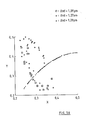
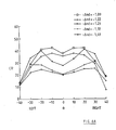
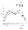
- the contrast ratio can be made large in the area where the contrast ratio of the primary cell is maximum (refer to Fig. 3, Fig. 6A, and Fig. 6B). As evident from Fig. 5A, however, the dependence of a black level colour on a visual angle is large, and the colour varies depending upon the visual angle (from green to reddish violet, or vice versa).
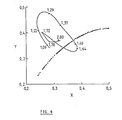
- the variation in the chromaticity of the black level approaches the locus of the black body (as represented by a series of dots in Figs. 4 and 5B) and its dependence on the visual angle has been small (refer to Fig. 4 and Fig. 5B).
- the background colour is stabilized in a reddish violet region.
- the chromaticity of the black level (normal direction) is near the locus of a black body, and its dependence on the visual angle becomes inclined to sandwich the locus of the black body and to spread on both sides of it (refer to Fig. 4 and Fig. 5B).
- the background colour is reddish violet and comparatively stable.
- the chromaticity (normal direction) of the black level tends to move away from the vicinity of the locus of the black body (refer to Fig. 4).
- the absolute value of the contrast is lower compared with the example of the Experiment 6 and the dependence of the chromaticity on the visual angle is lower compared with the example of the Experiment 6, and especially the visual angle on the left side narrows (refer to Fig. 6C).
- the background colour is around green, and varies to reddish violet depending on the visual angle.
- the chromaticity of the black level tends to be approach the locus of the black body (refer to Fig. 4), and the value of the contrast is not inferior (refer to Fig. 6D).
- the background colour is around dark green, and it varies to reddish violet when the visual angle is large. Since the optical response speed of a liquid crystal is increased in proportion to the square of the thickness d of a cell (response is slow), in view of a thin cell being better, the advantage decreases when the chromaticity goes outside the region specified.
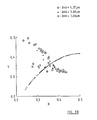
- the chromaticity of the black level tends to approach the locus of the black body closer than in the example of the Experiment 8 (refer to Fig. 4), and the dependence thereof on the visual angle is small (Fig. 5C).
- the dependence of the contrast on the visual angle is large, and especially the value of the contrast when the visual angle increases in the upward direction is apparently lower (refer to Fig. 3, Fig. 6C, and Fig. 6D).
- the thickness of the cell d is large, there is no advantage from the viewpoint of the response speed.
- the chromaticity in the normal direction approaches achromatic colour, and the contrast ratio tends to increase with increase of ⁇ nd.
- the background colour varies from green to reddish violet depending on the visual angle.
- the contrast ratio is comparatively stable, with the increase of ⁇ nd, and the characteristic of the visual angle as it increases in the upward direction deteriorates.
- a thinner cell is desirable from the viewpoint of response speed. From this viewpoint, the advantage is small if ⁇ nd exceeds 1.7 ⁇ m.
- the thickness d of the cell is varied with the double refraction index ⁇ n set to 0.1325 constant.
- the double refraction index ⁇ n of the liquid crystal layer is varied with the thickness d set to a constant, or both the thickness d of the cell and the double refraction index ⁇ n are varied, the same effect is obtained.
- each display device has the following advantages:
Landscapes
- Physics & Mathematics (AREA)
- Nonlinear Science (AREA)
- Chemical & Material Sciences (AREA)
- Crystallography & Structural Chemistry (AREA)
- General Physics & Mathematics (AREA)
- Optics & Photonics (AREA)
- Liquid Crystal (AREA)
Applications Claiming Priority (2)
| Application Number | Priority Date | Filing Date | Title |
|---|---|---|---|
| JP283760/88 | 1988-11-11 | ||
| JP63283760A JPH02130521A (ja) | 1988-11-11 | 1988-11-11 | ツイステッド・ネマチック液晶表示装置 |
Publications (3)
| Publication Number | Publication Date |
|---|---|
| EP0368554A2 true EP0368554A2 (de) | 1990-05-16 |
| EP0368554A3 EP0368554A3 (en) | 1990-08-22 |
| EP0368554B1 EP0368554B1 (de) | 1994-07-27 |
Family
ID=17669762
Family Applications (1)
| Application Number | Title | Priority Date | Filing Date |
|---|---|---|---|
| EP89311326A Expired - Lifetime EP0368554B1 (de) | 1988-11-11 | 1989-11-01 | Verdrillt-nematische Flüssigkristall-Anzeigevorrichtung |
Country Status (5)
| Country | Link |
|---|---|
| US (1) | US5091794A (de) |
| EP (1) | EP0368554B1 (de) |
| JP (1) | JPH02130521A (de) |
| CA (1) | CA2002427C (de) |
| DE (1) | DE68917086T2 (de) |
Cited By (1)
| Publication number | Priority date | Publication date | Assignee | Title |
|---|---|---|---|---|
| EP0637773A1 (de) * | 1993-08-04 | 1995-02-08 | Sharp Kabushiki Kaisha | Flüssigkristall-Anzeigevorrichtung |
Families Citing this family (11)
| Publication number | Priority date | Publication date | Assignee | Title |
|---|---|---|---|---|
| TW200604B (de) * | 1991-09-17 | 1993-02-21 | Philips Nv | |
| GB2276730A (en) * | 1993-03-15 | 1994-10-05 | Sharp Kk | Liquid crystal display |
| DE69427668T2 (de) * | 1993-08-04 | 2002-06-20 | Matsushita Electric Industrial Co., Ltd. | Verfahren zur Herstellung einer Flüssigkristall-Anzeigevorrichtung mit Orientierungsschicht für willkürliche Ausrichtung |
| JP3732242B2 (ja) * | 1994-02-18 | 2006-01-05 | シャープ株式会社 | 液晶表示装置 |
| US5745200A (en) * | 1994-04-28 | 1998-04-28 | Casio Computer Co., Ltd. | Color liquid crystal display device and liquid crystal display apparatus |
| KR20000016257A (ko) * | 1997-04-22 | 2000-03-25 | 모리시타 요이치 | 화상 판독기능을 가진 액정 표시장치, 화상판독방법 및 제조방법 |
| JP4634594B2 (ja) * | 2000-10-27 | 2011-02-16 | オプトレックス株式会社 | 液晶表示装置 |
| TWI278827B (en) * | 2004-05-12 | 2007-04-11 | Seiko Epson Corp | Display equipment and electronic apparatus |
| JP2011075745A (ja) * | 2009-09-30 | 2011-04-14 | Sony Corp | 画像表示観察システム、光変調器、及び画像表示装置 |
| TW201323997A (zh) * | 2011-12-02 | 2013-06-16 | Chimei Innolux Corp | 液晶顯示裝置 |
| JP6359338B2 (ja) * | 2014-05-22 | 2018-07-18 | スタンレー電気株式会社 | 液晶表示装置 |
Family Cites Families (17)
| Publication number | Priority date | Publication date | Assignee | Title |
|---|---|---|---|---|
| JPS54135551A (en) * | 1978-04-12 | 1979-10-20 | Sharp Corp | Multilayer liquid crystal display device |
| US4443065A (en) * | 1980-12-09 | 1984-04-17 | Sharp Kabushiki Kaisha | Interference color compensation double layered twisted nematic display |
| JPS57125919A (en) * | 1981-01-30 | 1982-08-05 | Sharp Corp | Two layer type liquid crystal display device |
| US4527864A (en) * | 1983-03-29 | 1985-07-09 | Xerox Corporation | High contrast liquid crystal display devices |
| JPS61210324A (ja) * | 1985-03-15 | 1986-09-18 | Hitachi Ltd | 液晶表示素子 |
| JPS61256324A (ja) * | 1985-05-10 | 1986-11-13 | Hitachi Ltd | 液晶表示素子 |
| JPS6231822A (ja) * | 1985-08-02 | 1987-02-10 | Hitachi Ltd | 液晶表示素子 |
| JPS62180327A (ja) * | 1986-02-04 | 1987-08-07 | Fujitsu Ltd | 液晶表示パネル |
| JPH083584B2 (ja) * | 1986-04-14 | 1996-01-17 | セイコーエプソン株式会社 | 液晶光シヤツタ |
| JPS62279315A (ja) * | 1986-05-28 | 1987-12-04 | Ricoh Co Ltd | 液晶表示素子 |
| JP2676508B2 (ja) * | 1986-09-12 | 1997-11-17 | コニカ株式会社 | 液晶表示装置 |
| JP2742788B2 (ja) * | 1986-10-31 | 1998-04-22 | セイコーエプソン株式会社 | 投射型表示装置 |
| EP0266184B1 (de) * | 1986-10-31 | 1995-04-12 | Seiko Epson Corporation | Anzeigevorrichtung vom Projektionstyp |
| JPS6415720A (en) * | 1987-07-09 | 1989-01-19 | Asahi Glass Co Ltd | Liquid crystal display element |
| US4906073A (en) * | 1987-07-29 | 1990-03-06 | Hitachi, Ltd. | Liquid crystal display device using nematic liquid crystal having twisted helical structure and a phase correction plate |
| JPH01214818A (ja) * | 1988-02-23 | 1989-08-29 | Alps Electric Co Ltd | 液晶素子 |
| JPH01216318A (ja) * | 1988-02-24 | 1989-08-30 | Alps Electric Co Ltd | 液晶素子 |
-
1988
- 1988-11-11 JP JP63283760A patent/JPH02130521A/ja active Pending
-
1989
- 1989-11-01 DE DE68917086T patent/DE68917086T2/de not_active Expired - Fee Related
- 1989-11-01 EP EP89311326A patent/EP0368554B1/de not_active Expired - Lifetime
- 1989-11-07 CA CA002002427A patent/CA2002427C/en not_active Expired - Fee Related
- 1989-11-13 US US07/434,747 patent/US5091794A/en not_active Expired - Fee Related
Cited By (1)
| Publication number | Priority date | Publication date | Assignee | Title |
|---|---|---|---|---|
| EP0637773A1 (de) * | 1993-08-04 | 1995-02-08 | Sharp Kabushiki Kaisha | Flüssigkristall-Anzeigevorrichtung |
Also Published As
| Publication number | Publication date |
|---|---|
| CA2002427A1 (en) | 1990-05-11 |
| CA2002427C (en) | 1994-01-11 |
| EP0368554B1 (de) | 1994-07-27 |
| US5091794A (en) | 1992-02-25 |
| DE68917086D1 (de) | 1994-09-01 |
| JPH02130521A (ja) | 1990-05-18 |
| EP0368554A3 (en) | 1990-08-22 |
| DE68917086T2 (de) | 1995-03-09 |
Similar Documents
| Publication | Publication Date | Title |
|---|---|---|
| EP2485088B1 (de) | Vertikal ausgerichtete Flüssigkristallanzeige unter Verwendung eines zweiachsigen Verzögerungskompensierungsfilms | |
| EP1588211B1 (de) | Vertikal ausgerichtete flüssigkristallanzeige mit einem negativ-kompensationsfilm | |
| EP1588212B1 (de) | Vertikal ausgerichtete flüssigkristallanzeige mit einem positiv-kompensationsfilm | |
| EP3153920B1 (de) | Auf gleicher ebene schaltende flüssigkristallanzeige mit ausgleichfolie für winkliges blickfeld unter verwendung einer positiven biaxialen verzögerungsfolie | |
| EP0512459B1 (de) | Flüssigkristallanzeige | |
| KR100246871B1 (ko) | 컬러 액정 디스플레이 구동 방법 | |
| US6339460B1 (en) | Liquid crystal display device | |
| KR100254041B1 (ko) | 액정층의 잔류위상차를 보상한 액정표시장치 | |
| KR960007791B1 (ko) | 전기 광학 소자 | |
| EP0412844A1 (de) | Flüssigkristallanzeige | |
| EP0793134A1 (de) | Flüssigkristallanzeige mit alternierenden Elektrodeneinschnitten | |
| EP0341702B1 (de) | Flüssigkristall-Anzeigevorrichtung | |
| EP0368554A2 (de) | Verdrillt-nematische Flüssigkristall-Anzeigevorrichtung | |
| EP0410949A2 (de) | Flüssigkristallanzeige | |
| US4859037A (en) | Liquid crystal electrically-controlled birefringence display devices with improved contrast | |
| EP0359280A2 (de) | Vorrichtung mit einem Flüssigkristall | |
| US7499127B2 (en) | Liquid crystal display device having red, green and blue filters in which the liquid crystal layer thickness for the red filter portion is equal to the green filter portion but greater than the blue filter portion | |
| US5629786A (en) | Liquid crystal display device | |
| JPH07175076A (ja) | 液晶表示素子 | |
| EP0727691A1 (de) | Flüssigkristall-Anzeigevorrichtung mit aktiver Matrix und homogen ausgerichtetem, nicht verdrillten Flüssigkristall, sowie Kompensation der Verzögerung | |
| EP0349006A2 (de) | Flüssigkristall-Vorrichtung | |
| EP0638834A2 (de) | Anzeigevorrichtung mit Pi-Zellen-Anordnung und Verzögerungskompensation | |
| JP3006155B2 (ja) | 液晶表示装置 | |
| EP0571996A1 (de) | Flüssigkristallanzeigevorrichtung | |
| JPH0534676A (ja) | 液晶表示装置 |
Legal Events
| Date | Code | Title | Description |
|---|---|---|---|
| PUAI | Public reference made under article 153(3) epc to a published international application that has entered the european phase |
Free format text: ORIGINAL CODE: 0009012 |
|
| AK | Designated contracting states |
Kind code of ref document: A2 Designated state(s): DE FR GB IT |
|
| PUAL | Search report despatched |
Free format text: ORIGINAL CODE: 0009013 |
|
| AK | Designated contracting states |
Kind code of ref document: A3 Designated state(s): DE FR GB IT |
|
| 17P | Request for examination filed |
Effective date: 19900926 |
|
| 17Q | First examination report despatched |
Effective date: 19920515 |
|
| GRAA | (expected) grant |
Free format text: ORIGINAL CODE: 0009210 |
|
| AK | Designated contracting states |
Kind code of ref document: B1 Designated state(s): DE FR GB IT |
|
| PG25 | Lapsed in a contracting state [announced via postgrant information from national office to epo] |
Ref country code: IT Free format text: LAPSE BECAUSE OF FAILURE TO SUBMIT A TRANSLATION OF THE DESCRIPTION OR TO PAY THE FEE WITHIN THE PRE;WARNING: LAPSES OF ITALIAN PATENTS WITH EFFECTIVE DATE BEFORE 2007 MAY HAVE OCCURRED AT ANY TIME BEFORE 2007. THE CORRECT EFFECTIVE DATE MAY BE DIFFERENT FROM THE ONE RECORDED.SCRIBED TIME-LIMIT Effective date: 19940727 |
|
| REF | Corresponds to: |
Ref document number: 68917086 Country of ref document: DE Date of ref document: 19940901 |
|
| ET | Fr: translation filed | ||
| PLBE | No opposition filed within time limit |
Free format text: ORIGINAL CODE: 0009261 |
|
| STAA | Information on the status of an ep patent application or granted ep patent |
Free format text: STATUS: NO OPPOSITION FILED WITHIN TIME LIMIT |
|
| 26N | No opposition filed | ||
| PGFP | Annual fee paid to national office [announced via postgrant information from national office to epo] |
Ref country code: GB Payment date: 19951024 Year of fee payment: 7 |
|
| PGFP | Annual fee paid to national office [announced via postgrant information from national office to epo] |
Ref country code: FR Payment date: 19951107 Year of fee payment: 7 |
|
| PGFP | Annual fee paid to national office [announced via postgrant information from national office to epo] |
Ref country code: DE Payment date: 19951123 Year of fee payment: 7 |
|
| PG25 | Lapsed in a contracting state [announced via postgrant information from national office to epo] |
Ref country code: GB Effective date: 19961101 |
|
| GBPC | Gb: european patent ceased through non-payment of renewal fee |
Effective date: 19961101 |
|
| PG25 | Lapsed in a contracting state [announced via postgrant information from national office to epo] |
Ref country code: FR Effective date: 19970731 |
|
| PG25 | Lapsed in a contracting state [announced via postgrant information from national office to epo] |
Ref country code: DE Effective date: 19970801 |
|
| REG | Reference to a national code |
Ref country code: FR Ref legal event code: ST |