EP0368122B1 - Mehrstufige Roots-Vakuumpumpe - Google Patents
Mehrstufige Roots-Vakuumpumpe Download PDFInfo
- Publication number
- EP0368122B1 EP0368122B1 EP89120179A EP89120179A EP0368122B1 EP 0368122 B1 EP0368122 B1 EP 0368122B1 EP 89120179 A EP89120179 A EP 89120179A EP 89120179 A EP89120179 A EP 89120179A EP 0368122 B1 EP0368122 B1 EP 0368122B1
- Authority
- EP
- European Patent Office
- Prior art keywords
- stator
- compression
- shaft
- housing
- chamber
- Prior art date
- Legal status (The legal status is an assumption and is not a legal conclusion. Google has not performed a legal analysis and makes no representation as to the accuracy of the status listed.)
- Revoked
Links
Images


Classifications
-
- F—MECHANICAL ENGINEERING; LIGHTING; HEATING; WEAPONS; BLASTING
- F04—POSITIVE - DISPLACEMENT MACHINES FOR LIQUIDS; PUMPS FOR LIQUIDS OR ELASTIC FLUIDS
- F04C—ROTARY-PISTON, OR OSCILLATING-PISTON, POSITIVE-DISPLACEMENT MACHINES FOR LIQUIDS; ROTARY-PISTON, OR OSCILLATING-PISTON, POSITIVE-DISPLACEMENT PUMPS
- F04C27/00—Sealing arrangements in rotary-piston pumps specially adapted for elastic fluids
- F04C27/008—Sealing arrangements in rotary-piston pumps specially adapted for elastic fluids for other than working fluid, i.e. the sealing arrangements are not between working chambers of the machine
- F04C27/009—Shaft sealings specially adapted for pumps
Definitions
- the present invention relates to a multi-stage roots type vacuum pump, comprising a stator defining a plurality of successive compression chambers, axially separated from each other by lateral flanges, a rotor assembly arranged inside the stator and consisting of two parallel shafts supported by bearings in end flanges of the stator, each shaft being fitted in each chamber with a compression lobe, each chamber thus containing two lobes, conjugate, of compression, one of the two shafts being driven in rotation by a motor and the other shaft being driven in opposite directions by means of a gear located in a casing fixed to the corresponding end flange of the stator, the two shafts each passing through said flange through a seal lips.
- the pressure in the compression chamber closest to the casing which constitutes the high-pressure stage, may, depending on the value of the pressure at the suction of the pump, be greater than the pressure in the casing, it that is to say at atmospheric pressure, hence a risk of lifting the lip of the lip seal.
- the pressure could be balanced on either side of the joint by a communication tube between the casing and the compression chamber, but then there would be a risk of facilitating the passage of oil vapors through this tube, from the crankcase to the compression chamber and find traces of oil condensation in the latter.
- Document GB 2 089 892 describes a rotary piston pump in which a suction chamber is isolated from a gear chamber by labyrinth seals divided into two groups separated by a pressure equalization chamber connected to the chamber by an oil filter.
- Document GB 2 116 634 describes a single-stage compressor of the Roots type in which the end flange, adjacent to the casing containing the gears, is fitted for each shaft, on the one hand with a lip seal and on the other hand 'a double labyrinth seal and between the two is formed an annular chamber communicating, through a channel made in the end flange, with the outside of the compressor.
- the compression chamber adjacent to the casing is very hot due to the compression of the gases, and this high temperature is transmitted to the oil, which has the effect, on the one hand, of reducing its viscosity, with the consequence larger leaks, and on the other hand to cause greater vaporization of the oil making trapping of the vapors more difficult.
- the present invention aims to remedy these drawbacks, and relates to a multi-stage roots type vacuum pump as defined above, characterized in that a sealing module is interposed between said end flange located on the side of said casing, and the compression chamber adjacent to said casing, said module constituting a partition, fitted around each shaft of the part fixed of a labyrinth seal, each shaft being provided with the movable complementary part of the labyrinth seal, said movable parts of labyrinth seals being located in a common cavity of said module connected, by means of a valve, with the delivery channel from said compression chamber adjacent to said casing, said valve allowing a passage of fluid in the direction of said cavity towards said delivery channel.
- said sealing module includes a cooling water circulation chamber.
- an inert gas is injected in small quantity into said cavity.
- This pump 40 is composed of a stator and a rotor assembly.
- the stator is produced by an assembly by stack of wafers comprising lateral flanges 1 and of ends 2 and 3, and stator rings 4.
- This stator thus defines a plurality of successive compression chambers 5 delimited radially by the stator rings and axially by the flanges.
- the ends of the stator are closed by two covers 6 and 7.
- the rotor assembly disposed inside the stator comprises two parallel shafts 8 and 9 supported by rolling bearings 11 and 12 in the end flange 2 and also in the end flange 3.
- each compression chamber 5 the shaft 8 is equipped with a compression lobe 13 and the shaft 9 is equipped with a compression lobe 14.
- Each compression chamber 5 therefore receives two compression lobes: 13 and 14 These lobes have conjugate profiles and are well known in themselves.
- the shaft 8 is rotated by a drive motor 15 via a coupling device 16.
- the shaft 9 is rotated in opposite directions by a gear comprising a pinion 17 mounted on the shaft 8 and a pinion 18 mounted on the shaft 9.
- This gear 17-18 is located in the cover 6 serving as a casing.
- This housing cover 6 is fixed to the end flange 2. In operation, the housing 6 contains lubricating oil of the gear 17-18.
- the shaft 8 passes through the end flange 2 through a lip seal 19 and likewise, the shaft 9 passes through the end flange 2 through a lip seal 20.
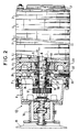
- FIG. 1 we see at 21 the suction inlet and at 22 the discharge outlet connected to the discharge channel 23 (FIG. 2) by various members including a silencer 24.
- the discharge channel 23 passes through the last stator ring 4 located on the side of the casing 6.
- the high pressure, atmospheric pressure in steady state, is therefore located on the side of the gear 17-18.
- a sealing module 24 interposed between the end flange 2 and the last compression chamber 5, that is to say between the flange 2 and the last stator ring 4 most close to the housing 6.
- This sealing module 24 constitutes a partition through which the shafts 8 and 9 pass; the partition being fitted around each shaft, with the fixed part 25, 26 of a labyrinth seal of which the second complementary, mobile part, 27, 28 is carried by the shafts 8 and 9.
- the mobile parts 27 and 28 of the labyrinth seals are mounted on the shafts via an O-ring 29, 30 and are located in a common cavity 31 of the module.
- This common cavity 31 is connected to the delivery channel 23 by a valve made up of a ball 32 pushed by a spring 33.
- the sealing module 24 comprises a chamber 34 for circulating cooling water. This circulation makes it possible to evacuate the calories generated in the neighboring compression chamber, and to keep the oil in the crankcase 6 at ambient temperature. A thermal barrier is thus produced.
- the water supply and drainage lines have not been shown in the drawing.
- the sealing module 24 also plays the role of an oil trap: in fact, if a leak nevertheless occurs through the lip seals 19 and 20 in the form of vapor, it is projected by the moving parts 27, 28 labyrinth seals acting as a deflector, against the wall cold, and condensed. If the leak is in liquid form, the O-rings 29, 30 prevent the migration of oil along the shafts. It is collected in the common cavity 31 from where it can be evacuated by a drain hole.
- each compression chamber has an inlet and an outlet, and the outlet of one chamber is connected to the inlet of the next through channels of the side flanges 1
Claims (3)
- Vakuumpumpe vom Mehrstufen-Roots-Typ, mit einem Stator, der eine Vielzahl von aufeinanderfolgenden Kompressionskammern (5) definiert, die axial voneinander durch seitliche Schilde (1) getrennt sind, wobei eine Rotoreinheit im Inneren des Stators angeordnet und aus zwei parallelen Wellen (8, 9) besteht, die von Lagern (11, 12) in Endflanschen (2, 3) des Stators getragen werden, wobei jede Welle (8, 9) in jeder Kammer (5) mit einem Kompressionswälzkolben (13, 14) ausgerüstet ist, so daß jede Kammer (5) zwei einander konjugierte Kompressionskolben (13, 14) enthält, wobei eine (8) der beiden Wellen durch einen Motor (15) in Drehung versetzt wird, während die andere Welle (9) in entgegengesetzter Richtung über ein Getriebe (17-18) angetrieben wird, das in einem Gehäuse (6) angeordnet ist, welches am entsprechenden Endschild (2) des Stators befestigt ist, wobei die beiden Wellen (8, 9) jeweils den Endschild (2) über eine Lippendichtung (19, 20) durchdringen, dadurch gekennzeichnet, daß ein Abdichtungsmodul (24) zwischen den an der Seite des Gehäuses (6) befindlichen Endschild (2) und die dem Gehäuse benachbarte Kompressionskammer eingefügt ist, wobei der Modul (24) eine Trennwand bildet, die im Bereich um jede Welle (8, 9) mit dem feststehenden Teil (25, 26) einer Labyrinthdichtung ausgerüstet ist, während jede Welle mit dem beweglichen, komplementären Teil (27, 28) der Labyrinthdichtung ausgestattet ist, wobei die beweglichen Teile der Labyrinthdichtungen in einem gemeinsamen Hohlraum (31) des Moduls angeordnet sind, der durch ein Ventil (32, 33) mit dem Auslaßkanal (23) der dem Gehäuse benachbarten Kompressionskammer verbunden ist, wobei das Ventil den Durchtritt eines Fluids in Richtung vom Hohlraum (31) zum Auslaßkanal ermöglicht.
- Vakuumpumpe nach Anspruch 1, dadurch gekennzeichnet, daß der Abdichtungsmodul (24) eine Kühlwasserumlaufkammer (34) aufweist.
- Vakuumpumpe nach Anspruch 1 oder 2, dadurch gekennzeichnet, daß ein Inertgas in geringer Menge in den gemeinsamen Hohlraum (31) eingespeist wird.
Priority Applications (1)
| Application Number | Priority Date | Filing Date | Title |
|---|---|---|---|
| AT89120179T ATE86011T1 (de) | 1988-11-07 | 1989-10-31 | Mehrstufige roots-vakuumpumpe. |
Applications Claiming Priority (2)
| Application Number | Priority Date | Filing Date | Title |
|---|---|---|---|
| FR8814494 | 1988-11-07 | ||
| FR8814494A FR2638788B1 (fr) | 1988-11-07 | 1988-11-07 | Pompe a vide du type roots multietage |
Publications (2)
| Publication Number | Publication Date |
|---|---|
| EP0368122A1 EP0368122A1 (de) | 1990-05-16 |
| EP0368122B1 true EP0368122B1 (de) | 1993-02-24 |
Family
ID=9371625
Family Applications (1)
| Application Number | Title | Priority Date | Filing Date |
|---|---|---|---|
| EP89120179A Revoked EP0368122B1 (de) | 1988-11-07 | 1989-10-31 | Mehrstufige Roots-Vakuumpumpe |
Country Status (8)
| Country | Link |
|---|---|
| US (1) | US4990069A (de) |
| EP (1) | EP0368122B1 (de) |
| JP (1) | JPH066950B2 (de) |
| AT (1) | ATE86011T1 (de) |
| DE (1) | DE68905026T2 (de) |
| ES (1) | ES2039804T3 (de) |
| FR (1) | FR2638788B1 (de) |
| RU (1) | RU1784072C (de) |
Families Citing this family (28)
| Publication number | Priority date | Publication date | Assignee | Title |
|---|---|---|---|---|
| WO1992014060A1 (de) * | 1991-02-01 | 1992-08-20 | Leybold Aktiengesellschaft | Trockenlaufende zweiwellenvakuumpumpe |
| FR2685392B1 (fr) * | 1991-12-18 | 1995-04-28 | Cit Alcatel | Dispositif pour assurer l'etancheite au lubrifiant de machines de transfert de gaz. |
| US6123526A (en) * | 1998-09-18 | 2000-09-26 | Industrial Technology Research Institute | Multistage pump and method for assembling the pump |
| DE20010216U1 (de) * | 2000-06-09 | 2001-10-18 | Hugo Vogelsang Maschb Gmbh | Axiale Dichtung |
| JP2002122088A (ja) | 2000-10-16 | 2002-04-26 | Toyota Industries Corp | 真空ポンプにおける流路構造 |
| JP2002221177A (ja) * | 2001-01-24 | 2002-08-09 | Toyota Industries Corp | 真空ポンプにおける軸封構造 |
| JP2002257070A (ja) * | 2001-02-28 | 2002-09-11 | Toyota Industries Corp | 真空ポンプにおける軸封構造 |
| JP4061850B2 (ja) * | 2001-02-28 | 2008-03-19 | 株式会社豊田自動織機 | 真空ポンプにおける軸封構造 |
| JP2002257244A (ja) * | 2001-02-28 | 2002-09-11 | Toyota Industries Corp | 真空ポンプにおける軸封構造 |
| JP2002332963A (ja) * | 2001-05-08 | 2002-11-22 | Toyota Industries Corp | 真空ポンプにおける油洩れ防止構造 |
| JP4747437B2 (ja) * | 2001-05-08 | 2011-08-17 | 株式会社豊田自動織機 | 真空ポンプにおける油洩れ防止構造 |
| JP2003013876A (ja) * | 2001-06-29 | 2003-01-15 | Toyota Industries Corp | 真空ポンプにおける油洩れ防止構造 |
| JP4617615B2 (ja) * | 2001-07-05 | 2011-01-26 | 株式会社豊田自動織機 | 真空ポンプにおける油洩れ防止構造 |
| US8979093B2 (en) | 2002-06-21 | 2015-03-17 | Inpro/Seal, LLC | Pressure balanced shaft seal assembly |
| US9004491B2 (en) * | 2002-06-21 | 2015-04-14 | Inpro/Seal Llc | Shaft seal assembly |
| CN100400881C (zh) * | 2002-08-23 | 2008-07-09 | 株式会社丰田自动织机 | 具有轴密封结构的真空泵 |
| JP3896930B2 (ja) * | 2002-09-10 | 2007-03-22 | 株式会社豊田自動織機 | 流体ポンプ装置 |
| DE10306547B4 (de) * | 2003-02-17 | 2005-08-04 | Aerzener Maschinenfabrik Gmbh | Drehkolbenmaschine |
| GB0310615D0 (en) * | 2003-05-08 | 2003-06-11 | Boc Group Plc | Improvements in seal assemblies |
| GB2408801A (en) * | 2003-12-03 | 2005-06-08 | Boc Group Plc | Detection of seal leak using differential pressure measurement |
| JP4844489B2 (ja) * | 2007-07-19 | 2011-12-28 | 株式会社豊田自動織機 | 流体機械 |
| GB0719394D0 (en) * | 2007-10-04 | 2007-11-14 | Edwards Ltd | A multi stage clam shell vacuum pump |
| JP4670854B2 (ja) * | 2007-11-05 | 2011-04-13 | 株式会社豊田自動織機 | 真空ポンプにおける軸封構造 |
| US9611847B2 (en) * | 2009-04-16 | 2017-04-04 | Eaton Industrial Corporation | Aircraft main engine fuel pump with multiple gear stages using shared journals |
| CN103899539A (zh) * | 2014-03-03 | 2014-07-02 | 苏州伊莱茨流体装备有限公司 | 一种具备自循环油密封系统的罗茨真空泵 |
| TWI735960B (zh) | 2018-09-28 | 2021-08-11 | 美商英普羅密封有限責任公司 | 環狀密封組件 |
| US11815095B2 (en) * | 2019-01-10 | 2023-11-14 | Elival Co., Ltd | Power saving vacuuming pump system based on complete-bearing-sealing and dry-large-pressure-difference root vacuuming root pumps |
| US11905950B2 (en) * | 2020-01-24 | 2024-02-20 | Circor Pumps North America, Llc. | Screw pump with improved sealing and bearing assembly |
Family Cites Families (6)
| Publication number | Priority date | Publication date | Assignee | Title |
|---|---|---|---|---|
| US937916A (en) * | 1909-04-22 | 1909-10-26 | Bliss E W Co | Steam-packing. |
| DE3047699A1 (de) * | 1980-12-18 | 1982-07-01 | Arthur Pfeiffer Vakuumtechnik Wetzlar Gmbh, 6334 Asslar | Waelzkolbenpumpe mit druckausgleichskammer |
| IT1155126B (it) * | 1982-03-10 | 1987-01-21 | Fiat Auto Spa | Compressore volumetrico rotativo del tipo roots |
| JPS59213984A (ja) * | 1983-05-20 | 1984-12-03 | Nippon Piston Ring Co Ltd | ベ−ン形回転圧縮機の軸受装置 |
| JPS61252889A (ja) * | 1985-04-23 | 1986-11-10 | Anretsuto:Kk | 多段式高圧用ル−ツブロワ− |
| JPH0733834B2 (ja) * | 1986-12-18 | 1995-04-12 | 株式会社宇野澤組鐵工所 | ロータ内蔵ハウジングの外周温度が安定化された内部分流逆流冷却多段式の三葉式真空ポンプ |
-
1988
- 1988-11-07 FR FR8814494A patent/FR2638788B1/fr not_active Expired - Fee Related
-
1989
- 1989-10-31 AT AT89120179T patent/ATE86011T1/de not_active IP Right Cessation
- 1989-10-31 ES ES198989120179T patent/ES2039804T3/es not_active Expired - Lifetime
- 1989-10-31 EP EP89120179A patent/EP0368122B1/de not_active Revoked
- 1989-10-31 DE DE8989120179T patent/DE68905026T2/de not_active Revoked
- 1989-11-04 RU SU894742466A patent/RU1784072C/ru active
- 1989-11-06 US US07/432,428 patent/US4990069A/en not_active Expired - Fee Related
- 1989-11-07 JP JP1289836A patent/JPH066950B2/ja not_active Expired - Lifetime
Also Published As
| Publication number | Publication date |
|---|---|
| EP0368122A1 (de) | 1990-05-16 |
| JPH066950B2 (ja) | 1994-01-26 |
| FR2638788A1 (fr) | 1990-05-11 |
| US4990069A (en) | 1991-02-05 |
| FR2638788B1 (fr) | 1994-01-28 |
| ES2039804T3 (es) | 1993-10-01 |
| JPH02157490A (ja) | 1990-06-18 |
| RU1784072C (ru) | 1992-12-23 |
| DE68905026T2 (de) | 1993-06-17 |
| ATE86011T1 (de) | 1993-03-15 |
| DE68905026D1 (de) | 1993-04-01 |
Similar Documents
| Publication | Publication Date | Title |
|---|---|---|
| EP0368122B1 (de) | Mehrstufige Roots-Vakuumpumpe | |
| BE1014892A5 (fr) | Compresseur a vis sans huile. | |
| FR2559847A1 (fr) | Machine a volutes pour comprimer un fluide | |
| FR2522736A1 (fr) | Systeme de lubrification du type brouillard auto-nettoyant a simple boucle pour compresseur a vis | |
| FR2559848A1 (fr) | Machine a volutes pour comprimer un fluide | |
| FR2969226A1 (fr) | Compresseur frigorifique a spirales | |
| FR2969227A1 (fr) | Compresseur frigorifique a spirales | |
| EP2402613B1 (de) | Trockenvakuumpumpe | |
| FR2607195A1 (fr) | Dispositif, tubulures et procede pour isoler un compresseur hors service d'un circuit | |
| CA2621837C (fr) | Systeme de deshuilage pour moteur d'aeronef | |
| FR3055360A1 (fr) | Ensemble de separateur huile-gaz et moteur a combustion interne | |
| FR2496776A1 (fr) | Pompe a pistons rotatifs a chambre d'egalisation de pression | |
| FR2525685A1 (fr) | Turbocompresseur pour moteurs a combustion interne | |
| FR2675213A1 (fr) | Systeme formant barriere pour l'huile de lubrification des paliers d'un compresseur centrifuge muni de joints d'etancheite a labyrinthe installe dans un environnement confine. | |
| FR3035164B1 (fr) | Transmission | |
| FR2548752A1 (fr) | Joint liquide pour gaz avec balayage de fluide | |
| FR2582741A1 (fr) | Pompe mecanique a plusieurs etages comportant des conduits centraux pour empecher les fuites de gaz | |
| JPS61152990A (ja) | スクリユ−真空ポンプ | |
| EP3775558B1 (de) | Trockenlaufende vakuumpumpe | |
| FR3106630A1 (fr) | Pompe à vide sèche | |
| FR2817922A1 (fr) | Compresseurs de type a volutes | |
| FR2661954A1 (fr) | Pompe a vide alternative. | |
| FR2482208A1 (de) | ||
| FR3067386B1 (fr) | Machine de detente | |
| FR3073567A1 (fr) | Systeme de deux turbocompresseurs relies en serie |
Legal Events
| Date | Code | Title | Description |
|---|---|---|---|
| PUAI | Public reference made under article 153(3) epc to a published international application that has entered the european phase |
Free format text: ORIGINAL CODE: 0009012 |
|
| AK | Designated contracting states |
Kind code of ref document: A1 Designated state(s): AT BE CH DE ES FR GB GR IT LI LU NL SE |
|
| 17P | Request for examination filed |
Effective date: 19901112 |
|
| 17Q | First examination report despatched |
Effective date: 19910919 |
|
| GRAA | (expected) grant |
Free format text: ORIGINAL CODE: 0009210 |
|
| AK | Designated contracting states |
Kind code of ref document: B1 Designated state(s): AT BE CH DE ES FR GB GR IT LI LU NL SE |
|
| PG25 | Lapsed in a contracting state [announced via postgrant information from national office to epo] |
Ref country code: SE Effective date: 19930224 Ref country code: AT Effective date: 19930224 |
|
| REF | Corresponds to: |
Ref document number: 86011 Country of ref document: AT Date of ref document: 19930315 Kind code of ref document: T |
|
| GBT | Gb: translation of ep patent filed (gb section 77(6)(a)/1977) |
Effective date: 19930302 |
|
| REF | Corresponds to: |
Ref document number: 68905026 Country of ref document: DE Date of ref document: 19930401 |
|
| ITF | It: translation for a ep patent filed |
Owner name: JACOBACCI CASETTA & PERANI S.P.A. |
|
| PG25 | Lapsed in a contracting state [announced via postgrant information from national office to epo] |
Ref country code: GR Free format text: LAPSE BECAUSE OF FAILURE TO SUBMIT A TRANSLATION OF THE DESCRIPTION OR TO PAY THE FEE WITHIN THE PRESCRIBED TIME-LIMIT Effective date: 19930528 |
|
| PGFP | Annual fee paid to national office [announced via postgrant information from national office to epo] |
Ref country code: GB Payment date: 19930825 Year of fee payment: 5 |
|
| PGFP | Annual fee paid to national office [announced via postgrant information from national office to epo] |
Ref country code: ES Payment date: 19930910 Year of fee payment: 5 |
|
| PGFP | Annual fee paid to national office [announced via postgrant information from national office to epo] |
Ref country code: DE Payment date: 19930922 Year of fee payment: 5 Ref country code: CH Payment date: 19930922 Year of fee payment: 5 |
|
| PGFP | Annual fee paid to national office [announced via postgrant information from national office to epo] |
Ref country code: FR Payment date: 19930930 Year of fee payment: 5 |
|
| REG | Reference to a national code |
Ref country code: ES Ref legal event code: FG2A Ref document number: 2039804 Country of ref document: ES Kind code of ref document: T3 |
|
| PG25 | Lapsed in a contracting state [announced via postgrant information from national office to epo] |
Ref country code: LU Free format text: LAPSE BECAUSE OF NON-PAYMENT OF DUE FEES Effective date: 19931031 Ref country code: BE Effective date: 19931031 |
|
| PGFP | Annual fee paid to national office [announced via postgrant information from national office to epo] |
Ref country code: NL Payment date: 19931031 Year of fee payment: 5 |
|
| PLBI | Opposition filed |
Free format text: ORIGINAL CODE: 0009260 |
|
| 26 | Opposition filed |
Opponent name: BALZERS- PFEIFFER GMBH Effective date: 19931115 |
|
| NLR1 | Nl: opposition has been filed with the epo |
Opponent name: BALZER- PFEIFFER GMBH |
|
| BERE | Be: lapsed |
Owner name: ALCATEL CIT Effective date: 19931031 |
|
| PG25 | Lapsed in a contracting state [announced via postgrant information from national office to epo] |
Ref country code: GB Effective date: 19941031 |
|
| PG25 | Lapsed in a contracting state [announced via postgrant information from national office to epo] |
Ref country code: ES Free format text: LAPSE BECAUSE OF NON-PAYMENT OF DUE FEES Effective date: 19941102 |
|
| NLV4 | Nl: lapsed or anulled due to non-payment of the annual fee | ||
| GBPC | Gb: european patent ceased through non-payment of renewal fee |
Effective date: 19941031 |
|
| REG | Reference to a national code |
Ref country code: CH Ref legal event code: PL |
|
| RDAG | Patent revoked |
Free format text: ORIGINAL CODE: 0009271 |
|
| STAA | Information on the status of an ep patent application or granted ep patent |
Free format text: STATUS: PATENT REVOKED |
|
| REG | Reference to a national code |
Ref country code: FR Ref legal event code: ST |
|
| 27W | Patent revoked |
Effective date: 19950414 |