EP0368122B1 - Multistage roots vacuum pump - Google Patents
Multistage roots vacuum pump Download PDFInfo
- Publication number
- EP0368122B1 EP0368122B1 EP89120179A EP89120179A EP0368122B1 EP 0368122 B1 EP0368122 B1 EP 0368122B1 EP 89120179 A EP89120179 A EP 89120179A EP 89120179 A EP89120179 A EP 89120179A EP 0368122 B1 EP0368122 B1 EP 0368122B1
- Authority
- EP
- European Patent Office
- Prior art keywords
- stator
- compression
- shaft
- housing
- chamber
- Prior art date
- Legal status (The legal status is an assumption and is not a legal conclusion. Google has not performed a legal analysis and makes no representation as to the accuracy of the status listed.)
- Revoked
Links
Images


Classifications
-
- F—MECHANICAL ENGINEERING; LIGHTING; HEATING; WEAPONS; BLASTING
- F04—POSITIVE - DISPLACEMENT MACHINES FOR LIQUIDS; PUMPS FOR LIQUIDS OR ELASTIC FLUIDS
- F04C—ROTARY-PISTON, OR OSCILLATING-PISTON, POSITIVE-DISPLACEMENT MACHINES FOR LIQUIDS; ROTARY-PISTON, OR OSCILLATING-PISTON, POSITIVE-DISPLACEMENT PUMPS
- F04C27/00—Sealing arrangements in rotary-piston pumps specially adapted for elastic fluids
- F04C27/008—Sealing arrangements in rotary-piston pumps specially adapted for elastic fluids for other than working fluid, i.e. the sealing arrangements are not between working chambers of the machine
- F04C27/009—Shaft sealings specially adapted for pumps
Definitions
- the present invention relates to a multi-stage roots type vacuum pump, comprising a stator defining a plurality of successive compression chambers, axially separated from each other by lateral flanges, a rotor assembly arranged inside the stator and consisting of two parallel shafts supported by bearings in end flanges of the stator, each shaft being fitted in each chamber with a compression lobe, each chamber thus containing two lobes, conjugate, of compression, one of the two shafts being driven in rotation by a motor and the other shaft being driven in opposite directions by means of a gear located in a casing fixed to the corresponding end flange of the stator, the two shafts each passing through said flange through a seal lips.
- the pressure in the compression chamber closest to the casing which constitutes the high-pressure stage, may, depending on the value of the pressure at the suction of the pump, be greater than the pressure in the casing, it that is to say at atmospheric pressure, hence a risk of lifting the lip of the lip seal.
- the pressure could be balanced on either side of the joint by a communication tube between the casing and the compression chamber, but then there would be a risk of facilitating the passage of oil vapors through this tube, from the crankcase to the compression chamber and find traces of oil condensation in the latter.
- Document GB 2 089 892 describes a rotary piston pump in which a suction chamber is isolated from a gear chamber by labyrinth seals divided into two groups separated by a pressure equalization chamber connected to the chamber by an oil filter.
- Document GB 2 116 634 describes a single-stage compressor of the Roots type in which the end flange, adjacent to the casing containing the gears, is fitted for each shaft, on the one hand with a lip seal and on the other hand 'a double labyrinth seal and between the two is formed an annular chamber communicating, through a channel made in the end flange, with the outside of the compressor.
- the compression chamber adjacent to the casing is very hot due to the compression of the gases, and this high temperature is transmitted to the oil, which has the effect, on the one hand, of reducing its viscosity, with the consequence larger leaks, and on the other hand to cause greater vaporization of the oil making trapping of the vapors more difficult.
- the present invention aims to remedy these drawbacks, and relates to a multi-stage roots type vacuum pump as defined above, characterized in that a sealing module is interposed between said end flange located on the side of said casing, and the compression chamber adjacent to said casing, said module constituting a partition, fitted around each shaft of the part fixed of a labyrinth seal, each shaft being provided with the movable complementary part of the labyrinth seal, said movable parts of labyrinth seals being located in a common cavity of said module connected, by means of a valve, with the delivery channel from said compression chamber adjacent to said casing, said valve allowing a passage of fluid in the direction of said cavity towards said delivery channel.
- said sealing module includes a cooling water circulation chamber.
- an inert gas is injected in small quantity into said cavity.
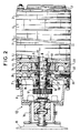
- This pump 40 is composed of a stator and a rotor assembly.
- the stator is produced by an assembly by stack of wafers comprising lateral flanges 1 and of ends 2 and 3, and stator rings 4.
- This stator thus defines a plurality of successive compression chambers 5 delimited radially by the stator rings and axially by the flanges.
- the ends of the stator are closed by two covers 6 and 7.
- the rotor assembly disposed inside the stator comprises two parallel shafts 8 and 9 supported by rolling bearings 11 and 12 in the end flange 2 and also in the end flange 3.
- each compression chamber 5 the shaft 8 is equipped with a compression lobe 13 and the shaft 9 is equipped with a compression lobe 14.
- Each compression chamber 5 therefore receives two compression lobes: 13 and 14 These lobes have conjugate profiles and are well known in themselves.
- the shaft 8 is rotated by a drive motor 15 via a coupling device 16.
- the shaft 9 is rotated in opposite directions by a gear comprising a pinion 17 mounted on the shaft 8 and a pinion 18 mounted on the shaft 9.
- This gear 17-18 is located in the cover 6 serving as a casing.
- This housing cover 6 is fixed to the end flange 2. In operation, the housing 6 contains lubricating oil of the gear 17-18.
- the shaft 8 passes through the end flange 2 through a lip seal 19 and likewise, the shaft 9 passes through the end flange 2 through a lip seal 20.
- FIG. 1 we see at 21 the suction inlet and at 22 the discharge outlet connected to the discharge channel 23 (FIG. 2) by various members including a silencer 24.
- the discharge channel 23 passes through the last stator ring 4 located on the side of the casing 6.
- the high pressure, atmospheric pressure in steady state, is therefore located on the side of the gear 17-18.
- a sealing module 24 interposed between the end flange 2 and the last compression chamber 5, that is to say between the flange 2 and the last stator ring 4 most close to the housing 6.
- This sealing module 24 constitutes a partition through which the shafts 8 and 9 pass; the partition being fitted around each shaft, with the fixed part 25, 26 of a labyrinth seal of which the second complementary, mobile part, 27, 28 is carried by the shafts 8 and 9.
- the mobile parts 27 and 28 of the labyrinth seals are mounted on the shafts via an O-ring 29, 30 and are located in a common cavity 31 of the module.
- This common cavity 31 is connected to the delivery channel 23 by a valve made up of a ball 32 pushed by a spring 33.
- the sealing module 24 comprises a chamber 34 for circulating cooling water. This circulation makes it possible to evacuate the calories generated in the neighboring compression chamber, and to keep the oil in the crankcase 6 at ambient temperature. A thermal barrier is thus produced.
- the water supply and drainage lines have not been shown in the drawing.
- the sealing module 24 also plays the role of an oil trap: in fact, if a leak nevertheless occurs through the lip seals 19 and 20 in the form of vapor, it is projected by the moving parts 27, 28 labyrinth seals acting as a deflector, against the wall cold, and condensed. If the leak is in liquid form, the O-rings 29, 30 prevent the migration of oil along the shafts. It is collected in the common cavity 31 from where it can be evacuated by a drain hole.
- each compression chamber has an inlet and an outlet, and the outlet of one chamber is connected to the inlet of the next through channels of the side flanges 1
Abstract
Description
La présente invention concerne une pompe à vide du type roots multiétagé, comprenant un stator définissant une pluralité de chambres successives de compression, séparées axialement les unes des autres par des flasques latéraux, un ensemble rotorique disposé à l'intérieur du stator et constitué de deux arbres parallèles supportés par des paliers dans des flasques d'extrémité du stator, chaque arbre étant équipé dans chaque chambre d'un lobe de compression, chaque chambre contenant ainsi deux lobes, conjugués, de compression, l'un des deux arbres étant entraîné en rotation par un moteur et l'autre arbre étant entraîné en sens inverse par l'intermédiaire d'un engrenage situé dans un carter fixé au flasque d'extrémité correspondant du stator, les deux arbres traversant chacun ledit flasque à travers un joint d'étanchéité à lèvres.The present invention relates to a multi-stage roots type vacuum pump, comprising a stator defining a plurality of successive compression chambers, axially separated from each other by lateral flanges, a rotor assembly arranged inside the stator and consisting of two parallel shafts supported by bearings in end flanges of the stator, each shaft being fitted in each chamber with a compression lobe, each chamber thus containing two lobes, conjugate, of compression, one of the two shafts being driven in rotation by a motor and the other shaft being driven in opposite directions by means of a gear located in a casing fixed to the corresponding end flange of the stator, the two shafts each passing through said flange through a seal lips.
Dans une pompe de ce type, il n'y a pas de joint d'huile entre les lobes de compression et les chambres de compression, il s'agit d'une pompe dite "sèche". Cependant le carter dans lequel est situé l'engrenage contient de l'huile pour la lubrification de l'engrenage, et bien que le carter soit séparé de la chambre de compression la plus proche par un joint à lèvre autour de chaque arbre, l'étanchéité qui en résulte est insuffisante lorsque l'on utilise une telle pompe en pompe primaire où l'on veut que les chambres de compression soient exemptes d'huile absolument.In a pump of this type, there is no oil seal between the compression lobes and the compression chambers, it is a so-called "dry" pump. However, the housing in which the gear is located contains oil for the lubrication of the gear, and although the housing is separated from the nearest compression chamber by a lip seal around each shaft, the The resulting tightness is insufficient when using such a pump as a primary pump where it is desired that the compression chambers be absolutely oil-free.
En effet, la pression dans la chambre de compression la plus proche du carter, qui constitue l'étage haute pression peut, selon la valeur de la pression à l'aspiration de la pompe, être supérieure à la pression dans le carter, c'est-à-dire à la pression atmosphérique, d'où un risque de soulèvement de la lèvre du joint à lèvre.In fact, the pressure in the compression chamber closest to the casing, which constitutes the high-pressure stage, may, depending on the value of the pressure at the suction of the pump, be greater than the pressure in the casing, it that is to say at atmospheric pressure, hence a risk of lifting the lip of the lip seal.
Pour remédier à ce problème, on pourrait équilibrer la pression de part et d'autre du joint par une tubulure de communication entre le carter et la chambre de compression, mais alors on risquerait de faciliter le passage de vapeurs d'huile par cette tubulure, du carter vers la chambre de compression et retrouver dans cette dernière des traces de condensation d'huile.To remedy this problem, the pressure could be balanced on either side of the joint by a communication tube between the casing and the compression chamber, but then there would be a risk of facilitating the passage of oil vapors through this tube, from the crankcase to the compression chamber and find traces of oil condensation in the latter.
L'utilisation d'un joint à deux lèvres montées tête-bêche est aussi à proscrire, car la lèvre côté chambre de compression ne peut être lubrifiée d'où son usure et une durée de vie très courte.The use of a joint with two lips mounted head to tail is also to be avoided, since the lip on the compression chamber side cannot be lubricated, hence its wear and a very short service life.
Le document GB 2 089 892 décrit une pompe à pistons rotatifs dans laquelle une chambre d'aspiration est isolée d'une chambre d'engrenage par des joints labyrinthes répartis en deux groupes séparées par une chambre d'égalisatation de pression reliée à la chambre d'engrenage par un filtre à huile.Document GB 2 089 892 describes a rotary piston pump in which a suction chamber is isolated from a gear chamber by labyrinth seals divided into two groups separated by a pressure equalization chamber connected to the chamber by an oil filter.
Le document GB 2 116 634 décrit un compresseur monoétagé du type Roots dans lequel le flasque d'extrémité, adjacent au carter contenant les engrenages, est équipé pour chaque arbre, d'une part d'un joint à lèvres et d'autre part d'un double joint labyrinthe et entre les deux est réalisée une chambre annulaire communiquant, par un canal effectué dans le flasque d'extrémité, avec l'extérieur du compresseur.Document GB 2 116 634 describes a single-stage compressor of the Roots type in which the end flange, adjacent to the casing containing the gears, is fitted for each shaft, on the one hand with a lip seal and on the other hand 'a double labyrinth seal and between the two is formed an annular chamber communicating, through a channel made in the end flange, with the outside of the compressor.
Grâce à cette mesure, on évite, en cas de pression excessive accidentelle dans la chambre du rotor de soumettre le joint à lèvres à une charge excessive ce qui compromettrait l'étanchéité.This measure prevents accidental excessive pressure in the rotor chamber from subjecting the lip seal to an excessive load, which would compromise the seal.
Dans le cas d'une pompe à vide une telle mesure ne peut pas être utilisée telle quelle, car, en régime établi, lorsque la pompe descend en pression, le joint labyrinthe laisserait passer un flux de retour venant de la pression atmosphérique externe ce qui détériorerait les performances de la pompe.In the case of a vacuum pump, such a measurement cannot be used as it is, because, in steady state, when the pump drops in pressure, the labyrinth seal would allow a return flow coming from the external atmospheric pressure to pass, which deteriorate pump performance.
Par ailleurs, la chambre de compression adjacente au carter est très chaude du fait de la compression des gaz, et cette haute température se transmet à l'huile, ce qui a pour effet, d'une part de diminuer sa viscosité, avec pour conséquence des fuites plus importantes, et d'autre part d'entraîner une vaporisation plus importante de l'huile rendant le piégeage des vapeurs plus difficile.Furthermore, the compression chamber adjacent to the casing is very hot due to the compression of the gases, and this high temperature is transmitted to the oil, which has the effect, on the one hand, of reducing its viscosity, with the consequence larger leaks, and on the other hand to cause greater vaporization of the oil making trapping of the vapors more difficult.
Enfin, les gaz pompés, s'ils sont corrosifs, peuvent rapidement endommager le joint d'étanchéité et provoquer des fuites.Finally, the pumped gases, if corrosive, can quickly damage the seal and cause leaks.
La présente invention a pour but de remédier à ces inconvénients, et a pour objet une pompe à vide du type roots multiétagé comme définie ci-dessus, caractérisée par le fait qu'un module d'étanchéité est interposé entre ledit flasque d'extrémité situé du côté dudit carter, et la chambre de compression adjacente audit carter, ledit module constituant une cloison, équipée autour de chaque arbre de la partie fixe d'un joint labyrinthe, chaque arbre étant muni de la partie complémentaire mobile du joint labyrinthe, lesdites parties mobiles de joints labyrinthes étant situées dans une cavité commune dudit module reliée, par l'intermédiaire d'une soupape, avec le canal de refoulement de ladite chambre de compression adjacente audit carter, ladite soupape permettant un passage de fluide dans le sens de ladite cavité vers ledit canal de refoulement.The present invention aims to remedy these drawbacks, and relates to a multi-stage roots type vacuum pump as defined above, characterized in that a sealing module is interposed between said end flange located on the side of said casing, and the compression chamber adjacent to said casing, said module constituting a partition, fitted around each shaft of the part fixed of a labyrinth seal, each shaft being provided with the movable complementary part of the labyrinth seal, said movable parts of labyrinth seals being located in a common cavity of said module connected, by means of a valve, with the delivery channel from said compression chamber adjacent to said casing, said valve allowing a passage of fluid in the direction of said cavity towards said delivery channel.
Selon une autre caractéristique, ledit module d'étanchéité comprend une chambre de circulation d'eau de refroidissement.According to another characteristic, said sealing module includes a cooling water circulation chamber.
Selon une autre caractéristique, un gaz inerte est injecté en faible quantité dans ladite cavité.According to another characteristic, an inert gas is injected in small quantity into said cavity.
On va maintenant donner la description d'un exemple de mise en oeuvre de l'invention en se référant au dessin annexé dans lequel :
- La figure 1 est une vue extérieure générale, très schématique, d'une pompe à vide selon l'invention.
- La figure 2 montre la pompe selon l'invention en élévation en coupe partielle.
- La figure 3 est une vue de dessus en coupe partielle de la pompe selon l'invention.
- Figure 1 is a general exterior view, very schematic, of a vacuum pump according to the invention.
- Figure 2 shows the pump according to the invention in elevation in partial section.
- Figure 3 is a top view in partial section of the pump according to the invention.
En se référant aux figures, on voit une pompe à vide du type roots multiétagé.Referring to the figures, we see a multi-stage roots type vacuum pump.
Cette pompe 40 est composée d'un stator et d'un ensemble rotorique. Le stator est réalisé par un assemblage par empilement de galettes comprenant des flasques latéraux 1 et d'extrémités 2 et 3, et des couronnes statoriques 4. Ce stator définit ainsi une pluralité de chambres de compression 5 successives délimitées radialement par les couronnes statoriques et axialement par les flasques. Les extrémités du stator sont fermées par deux couvercles 6 et 7.This
L'ensemble rotorique, disposé à l'intérieur du stator comprend deux arbres parallèles 8 et 9 supportés par des paliers à roulements 11 et 12 dans le flasque d'extrémité 2 et aussi dans le flasque d'extrémité 3.The rotor assembly, disposed inside the stator comprises two
Dans chaque chambre de compression 5, l'arbre 8 est équipé d'un lobe de compression 13 et l'arbre 9 est équipé d'un lobe de compression 14. Chaque chambre de compression 5 reçoit donc deux lobes de compression : 13 et 14. Ces lobes ont des profils conjugués et sont bien connus en eux-mêmes.In each
L'arbre 8 est entraîné en rotation par un moteur d'entraînement 15 par l'intermédiaire d'un dispositif d'accouplement 16. L'arbre 9 est entraîné en rotation en sens inverse par un engrenage comprenant un pignon 17 monté sur l'arbre 8 et un pignon 18 monté sur l'arbre 9. Cet engrenage 17-18 est situé dans le couvercle 6 servant de carter. Ce couvercle-carter 6 est fixé au flasque d'extrémité 2. En fonctionnement, le carter 6 contient de l'huile de lubrification de l'engrenage 17-18.The
L'arbre 8 traverse le flasque d'extrémité 2 à travers un joint d'étanchéité à lèvre 19 et de même, l'arbre 9 traverse le flasque d'extrémité 2 à travers un joint d'étanchéité à lèvre 20.The
Sur la figure 1, on voit en 21 l'entrée d'aspiration et en 22 la sortie de refoulement reliée au canal de refoulement 23 (figure 2) par différents organes dont un silencieux 24. Le canal de refoulement 23 traverse la dernière couronne statorique 4 située du côté du carter 6. La haute pression, pression atmosphérique en régime établi, est donc située du côté de l'engrenage 17-18.In FIG. 1, we see at 21 the suction inlet and at 22 the discharge outlet connected to the discharge channel 23 (FIG. 2) by various members including a
Au démarrage de la pompe, il se crée des surpressions dans les chambres de compression avales, la pompe agissant comme un compresseur avec un rapport de compression ; ainsi, lorsque l'aspiration 2 démarre à la pression atmosphérique, on peut arriver à la dernière chambre 5 à une pression notablement supérieure à la pression atmosphérique régnant dans le carter 6 provoquant, en l'absence de mesures, le soulèvement des joints à lèvres 19 et 20.When the pump starts, overpressures are created in the downstream compression chambers, the pump acting as a compressor with a compression ratio; thus, when the suction 2 starts at atmospheric pressure, it is possible to arrive at the
Ainsi, selon l'invention, on prévoit un module d'étanchéité 24 interposé entre le flasque d'extrémité 2 et la dernière chambre de compression 5, c'est-à-dire entre le flasque 2 et la dernière couronne statorique 4 la plus proche du carter 6.Thus, according to the invention, there is provided a
Ce module d'étanchéité 24 constitue une cloison traversée par les arbres 8 et 9 ; la cloison étant équipée autour de chaque arbre, de la partie fixe 25, 26 d'un joint labyrinthe dont la seconde partie complémentaire, mobile, 27, 28 est portée par les arbres 8 et 9. Les parties mobiles 27 et 28 des joints labyrinthes sont montées sur les arbres par l'intermédiaire d'un joint torique 29, 30 et sont situées dans une cavité commune 31 du module.This
Cette cavité commune 31 est reliée au canal de refoulement 23 par une soupape constituée d'une bille 32 poussée par un ressort 33.This
Ainsi, en cas de surpression dans la cavité commune 31, celle-ci est mise en communication avec le canal de refoulement 23. Il n'y a donc plus de risque de soulèvement du joint à lèvres 19.Thus, in the event of overpressure in the
En outre, le module d'étanchéité 24 comprend une chambre 34 de circulation d'eau de refroidissement. Cette circulation permet d'évacuer les calories générées dans la chambre de compression voisine, et de maintenir l'huile du carter 6 à la température ambiante. On réalise ainsi une barrière thermique. Les conduites d'amenée et d'évacuation d'eau n'ont pas été représentées sur le dessin.In addition, the
On prévoit également d'injecter en faible quantité dans la cavité commune 31 un gaz inerte tel que de l'azote qui permet de diluer les éventuels gaz corrosifs aspirés, évitant ainsi l'agression et la destruction du joint à lèvres 19.It is also planned to inject a small amount into the
Le module d'étanchéité 24 joue en outre un rôle de piège à huile : en effet, s'il se produit néanmoins une fuite par les joints à lèvre 19 et 20 sous forme de vapeur, elle est projetée, par les parties mobiles 27, 28 des joints labyrinthes agissant comme déflecteur, contre la paroi froide, et condensée. Si la fuite est sous forme liquide, les joints toriques 29, 30 empêchent la migration de l'huile le long des arbres. Elle est recueillie dans la cavité commune 31 d'où elle peut être évacuée par un trou de vidange.The
Bien entendu, mais cela ne fait pas partie de l'invention, chaque chambre de compression comporte une entrée et une sortie, et la sortie d'une chambre est reliée à l'entrée de la suivante en passant par des canaux des flasques latéraux 1. Ces dispositions sont connues et n'ont pas été représentées pour ne pas surcharger le dessin.Of course, but this is not part of the invention, each compression chamber has an inlet and an outlet, and the outlet of one chamber is connected to the inlet of the next through channels of the side flanges 1 These provisions are known and have not been shown so as not to overload the design.
Claims (3)
- A multistage Roots-type vacuum pump comprising
a stator defining a plurality of successive compression chambers (5) which are axially separated from one another by lateral flanges (1); a rotor assembly disposed indide the stator and constituted by two parallel shafts (8, 9) supported by bearings (11,12) in end plates (2, 3) of the stator, each shaft (8, 9) being fitted inside each chamber (5) with a compression lobe (13, 14) such that each chamber (5) thus contains two conjugate compression lobes (13, 14); with one (8) of the two shafts being driven in rotation by a motor (15), and the other shaft (9) being driven in the opposite direction by means of a gearing (17-18) situated in a housing (6) fixed to the corresponding end plate (2) of the stator, and the two shafts (8, 9) passing through said end plate (2) via a corresponding lip seal (19, 20); characterized in that a sealing module (24) is interposed between the said end plate (2) situated adjacent to said housing (6) and the compression chamber adjacent to said housing, said module (24) constituting a partition around each of the shafts (8, 9) and being supplied with the fixed portion (25, 26) of a corresponding labyrinth seal, whereas each shaft is provided with the moving complementary portion (27, 28) of the labyrinth seal, said moving portions of the labyrinth seals being situated in a common cavity (31) of said module, which cavity is connected via a valve (32, 33) to the rejection channel (23) from said compression chamber adjacent to said housing, said valve allowing fluid to flow from said cavity (31) into said rejection channel. - A vacuum pump according to claim 1, characterized in that said sealing module (24) includes a chamber (34) for the circulation of cooling water.
- A vacuum pump according to claim 1, characterized in that a small quantity of inert gas is injected into said common cavity (31).
Priority Applications (1)
| Application Number | Priority Date | Filing Date | Title |
|---|---|---|---|
| AT89120179T ATE86011T1 (en) | 1988-11-07 | 1989-10-31 | ROOTS MULTISTAGE VACUUM PUMP. |
Applications Claiming Priority (2)
| Application Number | Priority Date | Filing Date | Title |
|---|---|---|---|
| FR8814494 | 1988-11-07 | ||
| FR8814494A FR2638788B1 (en) | 1988-11-07 | 1988-11-07 | MULTI-STAGE ROOTS TYPE VACUUM PUMP |
Publications (2)
| Publication Number | Publication Date |
|---|---|
| EP0368122A1 EP0368122A1 (en) | 1990-05-16 |
| EP0368122B1 true EP0368122B1 (en) | 1993-02-24 |
Family
ID=9371625
Family Applications (1)
| Application Number | Title | Priority Date | Filing Date |
|---|---|---|---|
| EP89120179A Revoked EP0368122B1 (en) | 1988-11-07 | 1989-10-31 | Multistage roots vacuum pump |
Country Status (8)
| Country | Link |
|---|---|
| US (1) | US4990069A (en) |
| EP (1) | EP0368122B1 (en) |
| JP (1) | JPH066950B2 (en) |
| AT (1) | ATE86011T1 (en) |
| DE (1) | DE68905026T2 (en) |
| ES (1) | ES2039804T3 (en) |
| FR (1) | FR2638788B1 (en) |
| RU (1) | RU1784072C (en) |
Families Citing this family (28)
| Publication number | Priority date | Publication date | Assignee | Title |
|---|---|---|---|---|
| US5364245A (en) * | 1991-02-01 | 1994-11-15 | Leybold Aktiengesellschaft | Dry-running twin-shaft vacuum pump |
| FR2685392B1 (en) * | 1991-12-18 | 1995-04-28 | Cit Alcatel | DEVICE FOR SECURING THE LUBRICATION OF GAS TRANSFER MACHINES. |
| US6123526A (en) * | 1998-09-18 | 2000-09-26 | Industrial Technology Research Institute | Multistage pump and method for assembling the pump |
| DE20010216U1 (en) * | 2000-06-09 | 2001-10-18 | Hugo Vogelsang Maschb Gmbh | Axial seal |
| JP2002122088A (en) | 2000-10-16 | 2002-04-26 | Toyota Industries Corp | Channel structure in vacuum pump |
| JP2002221177A (en) * | 2001-01-24 | 2002-08-09 | Toyota Industries Corp | Shaft sealing structure of vacuum pump |
| JP2002257244A (en) * | 2001-02-28 | 2002-09-11 | Toyota Industries Corp | Shaft seal structure in vacuum pump |
| JP4061850B2 (en) * | 2001-02-28 | 2008-03-19 | 株式会社豊田自動織機 | Shaft seal structure in vacuum pump |
| JP2002257070A (en) * | 2001-02-28 | 2002-09-11 | Toyota Industries Corp | Shaft sealing structure of vacuum pump |
| JP4747437B2 (en) * | 2001-05-08 | 2011-08-17 | 株式会社豊田自動織機 | Oil leakage prevention structure in vacuum pump |
| JP2002332963A (en) * | 2001-05-08 | 2002-11-22 | Toyota Industries Corp | Oil leakage preventive structure in vacuum pump |
| JP2003013876A (en) * | 2001-06-29 | 2003-01-15 | Toyota Industries Corp | Oil leak preventive structure of vacuum pump |
| JP4617615B2 (en) * | 2001-07-05 | 2011-01-26 | 株式会社豊田自動織機 | Oil leakage prevention structure in vacuum pump |
| US8979093B2 (en) | 2002-06-21 | 2015-03-17 | Inpro/Seal, LLC | Pressure balanced shaft seal assembly |
| US9004491B2 (en) * | 2002-06-21 | 2015-04-14 | Inpro/Seal Llc | Shaft seal assembly |
| CN100400881C (en) * | 2002-08-23 | 2008-07-09 | 株式会社丰田自动织机 | Axle sealing structure for vacuum pump |
| JP3896930B2 (en) * | 2002-09-10 | 2007-03-22 | 株式会社豊田自動織機 | Fluid pump device |
| DE10306547B4 (en) * | 2003-02-17 | 2005-08-04 | Aerzener Maschinenfabrik Gmbh | Rotary engine |
| GB0310615D0 (en) * | 2003-05-08 | 2003-06-11 | Boc Group Plc | Improvements in seal assemblies |
| GB2408801A (en) * | 2003-12-03 | 2005-06-08 | Boc Group Plc | Detection of seal leak using differential pressure measurement |
| JP4844489B2 (en) * | 2007-07-19 | 2011-12-28 | 株式会社豊田自動織機 | Fluid machinery |
| GB0719394D0 (en) * | 2007-10-04 | 2007-11-14 | Edwards Ltd | A multi stage clam shell vacuum pump |
| JP4670854B2 (en) * | 2007-11-05 | 2011-04-13 | 株式会社豊田自動織機 | Shaft seal structure in vacuum pump |
| US9611847B2 (en) * | 2009-04-16 | 2017-04-04 | Eaton Industrial Corporation | Aircraft main engine fuel pump with multiple gear stages using shared journals |
| CN103899539A (en) * | 2014-03-03 | 2014-07-02 | 苏州伊莱茨流体装备有限公司 | Roots vacuum pump with self-circulation oil seal system |
| TWI735960B (en) | 2018-09-28 | 2021-08-11 | 美商英普羅密封有限責任公司 | Shaft seal assembly |
| US11815095B2 (en) * | 2019-01-10 | 2023-11-14 | Elival Co., Ltd | Power saving vacuuming pump system based on complete-bearing-sealing and dry-large-pressure-difference root vacuuming root pumps |
| EP4093972A4 (en) * | 2020-01-24 | 2023-02-22 | CIRCOR Pumps North America, LLC | Screw pump with improved sealing and bearing assembly |
Family Cites Families (6)
| Publication number | Priority date | Publication date | Assignee | Title |
|---|---|---|---|---|
| US937916A (en) * | 1909-04-22 | 1909-10-26 | Bliss E W Co | Steam-packing. |
| DE3047699A1 (en) * | 1980-12-18 | 1982-07-01 | Arthur Pfeiffer Vakuumtechnik Wetzlar Gmbh, 6334 Asslar | ROLLING PISTON PUMP WITH PRESSURE COMPENSATION CHAMBER |
| IT1155126B (en) * | 1982-03-10 | 1987-01-21 | Fiat Auto Spa | ROOTS TYPE ROTARY VOLUMETRIC COMPRESSOR |
| JPS59213984A (en) * | 1983-05-20 | 1984-12-03 | Nippon Piston Ring Co Ltd | Bearing device in vane type rotary compressor |
| JPS61252889A (en) * | 1985-04-23 | 1986-11-10 | Anretsuto:Kk | Multi-stage high pressure roots blower |
| JPH0733834B2 (en) * | 1986-12-18 | 1995-04-12 | 株式会社宇野澤組鐵工所 | Inner partial-flow reverse-flow cooling multistage three-leaf vacuum pump in which the outer peripheral temperature of the housing with built-in rotor is stabilized |
-
1988
- 1988-11-07 FR FR8814494A patent/FR2638788B1/en not_active Expired - Fee Related
-
1989
- 1989-10-31 DE DE8989120179T patent/DE68905026T2/en not_active Revoked
- 1989-10-31 EP EP89120179A patent/EP0368122B1/en not_active Revoked
- 1989-10-31 AT AT89120179T patent/ATE86011T1/en not_active IP Right Cessation
- 1989-10-31 ES ES198989120179T patent/ES2039804T3/en not_active Expired - Lifetime
- 1989-11-04 RU SU894742466A patent/RU1784072C/en active
- 1989-11-06 US US07/432,428 patent/US4990069A/en not_active Expired - Fee Related
- 1989-11-07 JP JP1289836A patent/JPH066950B2/en not_active Expired - Lifetime
Also Published As
| Publication number | Publication date |
|---|---|
| EP0368122A1 (en) | 1990-05-16 |
| FR2638788B1 (en) | 1994-01-28 |
| ES2039804T3 (en) | 1993-10-01 |
| JPH066950B2 (en) | 1994-01-26 |
| DE68905026T2 (en) | 1993-06-17 |
| US4990069A (en) | 1991-02-05 |
| JPH02157490A (en) | 1990-06-18 |
| DE68905026D1 (en) | 1993-04-01 |
| ATE86011T1 (en) | 1993-03-15 |
| RU1784072C (en) | 1992-12-23 |
| FR2638788A1 (en) | 1990-05-11 |
Similar Documents
| Publication | Publication Date | Title |
|---|---|---|
| EP0368122B1 (en) | Multistage roots vacuum pump | |
| BE1014892A5 (en) | Screw compressor oil free. | |
| FR2559848A1 (en) | VOLUME MACHINE FOR COMPRESSING A FLUID | |
| FR2522736A1 (en) | SINGLE LOOP SELF-CLEANING FOG TYPE LUBRICATION SYSTEM FOR SCREW COMPRESSOR | |
| FR2969226A1 (en) | SPIRAL REFRIGERATING COMPRESSOR | |
| FR2969227A1 (en) | SPIRAL REFRIGERATING COMPRESSOR | |
| EP2402613B1 (en) | Dry type vacuum pump | |
| FR2607195A1 (en) | DEVICE, TUBULES AND METHOD FOR ISOLATING AN OUT-OF-SERVICE COMPRESSOR OF A CIRCUIT | |
| FR3055360A1 (en) | OIL-GAS SEPARATOR AND INTERNAL COMBUSTION ENGINE ASSEMBLY | |
| FR2496776A1 (en) | ROTARY PISTON PUMP WITH PRESSURE EQUALIZING CHAMBER | |
| FR2525685A1 (en) | TURBOCHARGER FOR INTERNAL COMBUSTION ENGINES | |
| FR2675213A1 (en) | BARRIER SYSTEM FOR THE LUBRICATING OIL OF THE BEARINGS OF A CENTRIFUGAL COMPRESSOR PROVIDED WITH LABYRINTH SEALS INSTALLED IN A CONTAINED ENVIRONMENT. | |
| CA2621837A1 (en) | Aircraft engine oil removal system | |
| FR2548752A1 (en) | LIQUID GASKET FOR GASES WITH FLUID SCAN | |
| FR3035164B1 (en) | TRANSMISSION | |
| FR2582741A1 (en) | MULTI-STAGE MECHANICAL PUMP COMPRISING CENTRAL CONDUITS TO PREVENT GAS LEAKAGE | |
| JPS61152990A (en) | Screw vacuum pump | |
| EP3775558B1 (en) | Dry-type vacuum pump | |
| FR3106630A1 (en) | Dry vacuum pump | |
| FR2817922A1 (en) | VOLUTES TYPE COMPRESSORS | |
| FR2661954A1 (en) | Alternating vacuum pump | |
| FR2482208A1 (en) | ||
| FR3067386B1 (en) | RELAXATION MACHINE | |
| FR3073567A1 (en) | SYSTEM OF TWO TURBOCOMPRESSORS CONNECTED IN SERIES | |
| FR2549907A1 (en) | HERMETIC REFRIGERATION COMPRESSOR |
Legal Events
| Date | Code | Title | Description |
|---|---|---|---|
| PUAI | Public reference made under article 153(3) epc to a published international application that has entered the european phase |
Free format text: ORIGINAL CODE: 0009012 |
|
| AK | Designated contracting states |
Kind code of ref document: A1 Designated state(s): AT BE CH DE ES FR GB GR IT LI LU NL SE |
|
| 17P | Request for examination filed |
Effective date: 19901112 |
|
| 17Q | First examination report despatched |
Effective date: 19910919 |
|
| GRAA | (expected) grant |
Free format text: ORIGINAL CODE: 0009210 |
|
| AK | Designated contracting states |
Kind code of ref document: B1 Designated state(s): AT BE CH DE ES FR GB GR IT LI LU NL SE |
|
| PG25 | Lapsed in a contracting state [announced via postgrant information from national office to epo] |
Ref country code: SE Effective date: 19930224 Ref country code: AT Effective date: 19930224 |
|
| REF | Corresponds to: |
Ref document number: 86011 Country of ref document: AT Date of ref document: 19930315 Kind code of ref document: T |
|
| GBT | Gb: translation of ep patent filed (gb section 77(6)(a)/1977) |
Effective date: 19930302 |
|
| REF | Corresponds to: |
Ref document number: 68905026 Country of ref document: DE Date of ref document: 19930401 |
|
| ITF | It: translation for a ep patent filed |
Owner name: JACOBACCI CASETTA & PERANI S.P.A. |
|
| PG25 | Lapsed in a contracting state [announced via postgrant information from national office to epo] |
Ref country code: GR Free format text: LAPSE BECAUSE OF FAILURE TO SUBMIT A TRANSLATION OF THE DESCRIPTION OR TO PAY THE FEE WITHIN THE PRESCRIBED TIME-LIMIT Effective date: 19930528 |
|
| PGFP | Annual fee paid to national office [announced via postgrant information from national office to epo] |
Ref country code: GB Payment date: 19930825 Year of fee payment: 5 |
|
| PGFP | Annual fee paid to national office [announced via postgrant information from national office to epo] |
Ref country code: ES Payment date: 19930910 Year of fee payment: 5 |
|
| PGFP | Annual fee paid to national office [announced via postgrant information from national office to epo] |
Ref country code: DE Payment date: 19930922 Year of fee payment: 5 Ref country code: CH Payment date: 19930922 Year of fee payment: 5 |
|
| PGFP | Annual fee paid to national office [announced via postgrant information from national office to epo] |
Ref country code: FR Payment date: 19930930 Year of fee payment: 5 |
|
| REG | Reference to a national code |
Ref country code: ES Ref legal event code: FG2A Ref document number: 2039804 Country of ref document: ES Kind code of ref document: T3 |
|
| PG25 | Lapsed in a contracting state [announced via postgrant information from national office to epo] |
Ref country code: LU Free format text: LAPSE BECAUSE OF NON-PAYMENT OF DUE FEES Effective date: 19931031 Ref country code: BE Effective date: 19931031 |
|
| PGFP | Annual fee paid to national office [announced via postgrant information from national office to epo] |
Ref country code: NL Payment date: 19931031 Year of fee payment: 5 |
|
| PLBI | Opposition filed |
Free format text: ORIGINAL CODE: 0009260 |
|
| 26 | Opposition filed |
Opponent name: BALZERS- PFEIFFER GMBH Effective date: 19931115 |
|
| NLR1 | Nl: opposition has been filed with the epo |
Opponent name: BALZER- PFEIFFER GMBH |
|
| BERE | Be: lapsed |
Owner name: ALCATEL CIT Effective date: 19931031 |
|
| PG25 | Lapsed in a contracting state [announced via postgrant information from national office to epo] |
Ref country code: GB Effective date: 19941031 |
|
| PG25 | Lapsed in a contracting state [announced via postgrant information from national office to epo] |
Ref country code: ES Free format text: LAPSE BECAUSE OF NON-PAYMENT OF DUE FEES Effective date: 19941102 |
|
| NLV4 | Nl: lapsed or anulled due to non-payment of the annual fee | ||
| GBPC | Gb: european patent ceased through non-payment of renewal fee |
Effective date: 19941031 |
|
| REG | Reference to a national code |
Ref country code: CH Ref legal event code: PL |
|
| RDAG | Patent revoked |
Free format text: ORIGINAL CODE: 0009271 |
|
| STAA | Information on the status of an ep patent application or granted ep patent |
Free format text: STATUS: PATENT REVOKED |
|
| REG | Reference to a national code |
Ref country code: FR Ref legal event code: ST |
|
| 27W | Patent revoked |
Effective date: 19950414 |