EP0368029A1 - Procédé et dispositif de mesure pour le contrôle des mesures de protection dans les réseaux de tensions alternatives - Google Patents
Procédé et dispositif de mesure pour le contrôle des mesures de protection dans les réseaux de tensions alternatives Download PDFInfo
- Publication number
- EP0368029A1 EP0368029A1 EP89119127A EP89119127A EP0368029A1 EP 0368029 A1 EP0368029 A1 EP 0368029A1 EP 89119127 A EP89119127 A EP 89119127A EP 89119127 A EP89119127 A EP 89119127A EP 0368029 A1 EP0368029 A1 EP 0368029A1
- Authority
- EP
- European Patent Office
- Prior art keywords
- voltage
- constant current
- switch
- measuring method
- test
- Prior art date
- Legal status (The legal status is an assumption and is not a legal conclusion. Google has not performed a legal analysis and makes no representation as to the accuracy of the status listed.)
- Granted
Links
Images


Classifications
-
- G—PHYSICS
- G01—MEASURING; TESTING
- G01R—MEASURING ELECTRIC VARIABLES; MEASURING MAGNETIC VARIABLES
- G01R31/00—Arrangements for testing electric properties; Arrangements for locating electric faults; Arrangements for electrical testing characterised by what is being tested not provided for elsewhere
Definitions
- the invention relates to a measuring method of the type mentioned in the preamble of claim 1 and a circuit arrangement for performing this method.
- the contact voltage U B When checking pollution measures in AC voltage networks, the contact voltage U B , the internal network resistance R i , the loop resistance R Schl , the earth resistance R E and the switch-off behavior of residual current circuit breakers (FI switches) are determined. For this it is necessary to apply a test current to the protective conductor PE of the respective network. In the case of faulty networks, this test current can now result in a dangerous touch voltage on the protective conductor.
- a touch voltage is only considered dangerous if it meets certain limit values, e.g. in living rooms 50 V, exceeds. However, larger values are also permitted if they are limited to a maximum time of 200ms.
- test devices for monitoring protective measures in accordance with VDE 0100 meet the above conditions in that the duration during which a test current flows Is limited to 0.2 s. With a period of 20 ms in 50 Hz networks, 10 periods are available for the measurement, which is generally sufficient.
- KEMA already recommends a maximum time of 40 ms for touch voltages above 50 V for the territorial area of the Netherlands and it can be expected that Germany will follow suit.
- a measuring method which allows the measurement of touch voltages and in which a load current flows for several periods for the measurement according to the voltage reduction method. There is an idle period before each load period, so that the mains voltage can be measured both at idle and under load.
- the differential voltage between the measured open circuit voltage and the load voltage corresponds to the touch voltage to be determined, provided that measurements are made between the L and PE conductors of the network.
- the differential voltage is detected in a particularly simple manner in that the two rectified half-waves of the open circuit voltage are integrated and the two following rectified half-waves are integrated. The residual voltage remaining in the integrator corresponds to the differential voltage sought.
- the object of the invention is to provide a measuring method of the type mentioned in the preamble of claim 1, which allows to carry out the checking of protective measures in AC networks with a test current that flows in at least three consecutive periods, but still presents a risk due to high contact voltage is excluded. Furthermore, a circuit arrangement suitable for carrying out the measuring method is to be proposed.
- the solution according to the invention allows the main measurement, which is used to determine a certain measured variable, on the one hand, and the test measurement, which in the event of danger causes a safety shutdown of the test current, to run in parallel.
- the test measurements unlike the main measurement, run so quickly that their result is available before the safety time of 40 ms has expired, the test current can still be switched off within this time.
- the main measurement can only be carried out when the cause of the impermissibly high contact voltage has been eliminated. A risk due to excessive contact voltages is thus avoided.
- test current is switched off within 2 periods (40 ms)
- an expedient development of the subject matter of the invention provides that the test measurement is evaluated after one period. If you take into account that additional time is required for the evaluation of the test measurement and the switch-off process, this is in any case within a period, so that it can be switched off after a maximum of 2 periods.
- values should be used for the test measurement that are already available during the main measurement.
- the different ones are used to determine different measured variables serving main measurements, always work with the same circuit arrangement. The latter means that, for example, it is not possible to integrate both the main measurement and the test measurement at the same time if only one integrator is available. The respective test measurement must therefore be adapted to the main measurement.
- An advantageous further development of the subject of the invention therefore provides that, in those main measurements in which the measured variable is determined with the aid of the voltage reduction method, the voltage remaining at the output of the integrator after the completion of an integration cycle serves as a test value for the test measurement.
- the constant current serving as the test current is switched off as soon as a predetermined limit value is exceeded.
- the limit value corresponds to the limit value of the permissible touch voltage. Since the output voltage at the integrator increases after each integration cycle, the limit value must also be increased accordingly.
- a particularly simple method for switching off the constant current is to switch it on again every half-wave and to suppress the switch-on pulse required for this to effect the switch-off.
- the network provided with the RCD switch is either supplied with a constant current that corresponds to the nominal residual current or with a constant current that increases in stages. In the first case one measures the time until the FI switch trips, and in the second case one measures the current at which the FI switch trips. In both cases, the constant current must flow over a large number of periods in order to be able to carry out the main measurement in accordance with the regulations.
- a pilot measurement is first carried out, in which the mains voltage is recorded in no-load operation.
- This voltage value is saved and serves as a reference value for subsequent voltage measurements under load with a predetermined constant current.
- the latter serve as test measurements, which are each carried out in the first half-wave of a period and evaluated in the second half-wave.
- a switch-off command can be given after a period if the contact voltage is excessive.
- the respective touch voltage results from the difference between the stored reference value and the respective current test value.
- the constant current is programmable and its value can therefore be changed automatically.
- different constant currents are required.
- the constant current is preferably programmed to 30% of the nominal residual current in the residual current circuit breaker so that the measurement can be carried out without the FI switch being switched off.
- the switch-off time of the RCD is determined with the nominal fault current and its switch-off current is determined with the help of a constant current that is increased in stages.
- Too high a touch voltage may be simulated if e.g. the FI switch was switched off during the measurement but was still switched on at the time of the pilot measurement, so that the differential voltage corresponds to the value of the reference voltage. In order to rule out this case, the presence of the mains voltage is checked before a dangerous touch voltage is reported.
- the RCD did not switch off within the specified time when it was checked with the nominal residual current.
- an error message is only issued when it is certain that the constant current is still flowing in the last period of the test sequence. After the automatic measurement has ended, the constant current is switched off even without the FI switch interrupting the circuit.
- the load branch is of particular importance with regard to the circuit arrangement. It contains two elements in series, both of which enable the constant current to be switched off.
- the switch-on pulse which triggers the next half-wave of the constant current is suppressed, so that the constant current circuit no longer delivers current.
- the relay that interrupts the circuit during the upcoming half-wave is also activated. The relay thus works faster and also has a higher breaking capacity. With the help of the current monitoring, an interruption of the circuit can be verified in a simple manner.
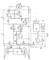
- the circuit arrangement shown in FIG. 1 is used to carry out various measuring methods, different measuring variables being determined which enable a check of protective measures in AC networks.
- the circuit contains a controlled two-way rectifier 3, which is connected with its input between phase L1 and the protective conductor PE of an AC voltage network to be checked. Depending on the type of measurement to be carried out, the two-pole input could also be connected between the phase and the neutral conductor.
- a controlled integrator 4 At the output of the controlled two-way rectifier 3 is a controlled integrator 4, the an A / D converter 5 is connected downstream.
- the output signal of the A / D converter 5 and a zero detector 6 are fed to a microprocessor 7.
- the input of the zero detector 6 is connected to a voltage divider R1, R2, which connects the mains connections L1, PE to one another and at the same time also forms the input of the controlled two-way rectifier 3.
- the mains voltage reduced by the voltage divider R1, R2 is fed from its tap to a first controlled switch S1, which is located at the input of the integrator 4.
- a second controlled switch S2, also connected to the input of the integrator 4 is preceded by an inverting amplifier V1, R3, R4, the input of which lies at the tap of the voltage divider R1, R2.
- the controlled integrator 4 includes an amplifier V2, which is bridged on the input side by a third controlled switch S3, and in whose negative feedback branch there is a charging capacitor C1 to which a fourth controlled switch S4 is connected in parallel.
- a load branch is connected to the input of the circuit arrangement between phase L1 and protective conductor PE, which consists of the series connection of a relay switch S5, a constant current circuit 1 and a current monitor 2.
- the relay switch S5 is actuated via a relay K1, which in turn is controlled by the computer 7 via the control connection a located on an upstream transistor.
- Further control connections b to h are also connected to the computer, which queries the respective measured values via the A / D converter 5 and, after their evaluation, displays the measurement result on a display 8.
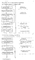
- the diagrams shown in FIG. 2 are intended to illustrate a measurement sequence as used in the measurement of the contact voltage, the internal network resistance, the loop resistance and the earth resistance.
- the voltage reduction method is used to determine these measured variables. This means that a load phase must follow an idle phase so that the mains voltage can be measured both at idle and under load. The difference between these two voltages is proportional to the measured variable sought.
- the duration of the load and idle phases is fixed to one period each.
- the constant current I K forming the load is thus interrupted after a period for the duration of a further period.
- a constant current I K is used in order to avoid load fluctuations which could falsify the measurement result.
- the diagram of the input voltage U E present at the input of the integrator 4 illustrates the mode of operation of the controlled two-way rectifier 3.
- the inverting amplifier V1, R3, R4 ensures that the mains AC voltage present at the controlled switch S2 is 180 ° with respect to the voltage present at the controlled switch S1 is shifted in phase.
- the two controlled switches S1, S2 are now switched in such a way that they effect rectification but in such a way that the polarity of the rectified AC voltage is reversed after each period.
- two negative half-waves follow each of two positive half-waves.
- the negative half-waves correspond to the load phase and accordingly have a slightly lower amplitude than the positive half-waves measured in idle.
- the diagram of the output voltage U A at the output of the integrator 4 reveals its mode of operation.
- the two positive half-waves of the input voltage U E are first integrated and then integrated with the two negative half-waves. Since the amplitude of the negative half-wave is lower due to the load, a residual voltage U A remains at the integrator output, which corresponds to the difference between the load and open circuit voltage.
- the constant current I K flowing in the load phase could lead to a dangerous touch voltage if the network is faulty.
- a precise measurement of the touch voltage over several integration cycles requires a time much longer than 40 ms. So that the constant current I K can be switched off immediately in the event of danger when the contact voltage is too high, a test measurement is carried out after each integration cycle, in which the output voltage U A determined during the main measurement is compared with a predetermined limit value U BL .
- the limit value U BL corresponds to the upper limit, the still permissible touch voltage U B and must be increased after each integration cycle. Because the output voltage at the integrator U A2 reaches approximately twice the value of U A1 , U BL2 must also be set to double and U BL3 to triple the value of U BL1 .
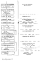
- the diagrams shown in FIG. 3 are intended to clarify the measurement sequence when checking an RCD. Its switching behavior is again examined with a constant current I K. To determine the switch-off time, a constant current labeled I K , is specified, which jumps to the full value of the nominal residual current of the respective RCD after switching on. The amplitude of the constant current could reach a value I K2 which is kept constant until the FI switch responds and is only switched off after the measurement has been completed.
- the value of the current at which the RCD switches off can be determined by increasing the amplitude of the constant current from a low value I K1 continuously or in stages. As indicated by curve I K ⁇ , the constant current after switching on reaches a base value of 30% of the nominal fault current and then increases to 100%.
- the constant current circuit 1 is programmed in such a way that the constant current increases in steps of 1%, so that the cut-off current of the FI switch results directly from the step value reached when switching off.
- the integrator 4 which is required anyway for the main measurement according to FIG. 2, is not required for the main measurement according to FIG. 3 explained above, so that it can be used for the test measurements required for touch voltage measurement.
- the controlled scarf ter S1, S2 switched so that only the positive half-wave U E reaches the input of the integrator 4. This voltage is integrated during the first half wave of a period. After the output voltage value has been taken over by the computer 7, the integrator is neutralized in the subsequent half-wave with the aid of the controlled switches S3, S4.
- the rough determination of the touch voltage which is to be carried out for safety reasons, is carried out in such a way that a pilot measurement is first carried out when the motor is idling and the output voltage U A1 determined in this way is stored. After switching on the constant current I K , the output voltage is measured again, a value U A2 being determined. This measurement is repeated every period. The difference between the two voltages U A1 and U A2 corresponds to the respective touch voltage. If the contact voltage exceeds the permissible value, the constant current circuit 1 and the relay switch S5 are switched off.
- a major advantage of the invention is that all main and test measurements can be carried out with the same circuit arrangement, so that no additional effort arises for the test measurements with regard to the required hardware.
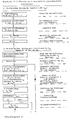
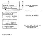
- Flow diagram 1 which consists of parts 1A and 1B, shows the individual steps of the measurement method that works according to the voltage reduction method.
- the actual measurement to determine the contact voltage, the loop resistance, the Internal resistance or the earth resistance is preceded by a preliminary test that is used to measure the AC line voltage L-PE.
- Their voltage value must be within the limits of -10% to +15% so that the automatic control of the measuring device enables the further measuring process.
- the individual steps of the diagram are sufficiently marked so that further explanations are not necessary.
- Flow diagram 2 with parts 2A and 2B describes the determination of the tripping time of RCDs, which is carried out with the aid of a constant constant current I K.
- I K constant constant current
- Parts 3A and 3B of flow chart 3 explain the method used to determine the tripping current of RCDs, in which a steadily increasing constant current I K is used. To understand the process, it should be added that in addition to the shutdown current I ⁇ , the contact voltage U B occurring at this current is also measured. If, as shown in flowchart 3A, the contact voltage U BN occurring at the rated fault current is initially determined at the beginning of the measurement process, this can be set at 100% like the rated fault current I ⁇ N .
- the constant current I K begins at a value of 30% of the nominal fault current I ⁇ N and then rises gradually . If the RCD does not switch off, I K would reach 100% at the end of the measurement, i.e. correspond to the nominal fault current. If the RCD trips at 70% of its rated fault current, see above the contact voltage U B present at this time also reaches 70% of the contact voltage U BN at the nominal fault current I ⁇ N . With the help of a flow counter (DL counter) mentioned in the flow diagram, which counts the seventy steps of the constant current increasing by 1% in each case, both the tripping current I ⁇ and the contact voltage U B present at this time can be recorded directly.
- DL counter flow counter
Landscapes
- Physics & Mathematics (AREA)
- General Physics & Mathematics (AREA)
- Measurement Of Current Or Voltage (AREA)
- Protection Of Static Devices (AREA)
- Emergency Protection Circuit Devices (AREA)
Applications Claiming Priority (2)
| Application Number | Priority Date | Filing Date | Title |
|---|---|---|---|
| DE3835710A DE3835710A1 (de) | 1988-10-20 | 1988-10-20 | Messverfahren und schaltungsanordnung zur ueberpruefung von schutzmassnahmen in wechselspannungsnetzen |
| DE3835710 | 1988-10-20 |
Publications (2)
| Publication Number | Publication Date |
|---|---|
| EP0368029A1 true EP0368029A1 (fr) | 1990-05-16 |
| EP0368029B1 EP0368029B1 (fr) | 1994-06-01 |
Family
ID=6365523
Family Applications (1)
| Application Number | Title | Priority Date | Filing Date |
|---|---|---|---|
| EP89119127A Expired - Lifetime EP0368029B1 (fr) | 1988-10-20 | 1989-10-14 | Procédé et dispositif de mesure pour le contrôle des mesures de protection dans les réseaux de tensions alternatives |
Country Status (3)
| Country | Link |
|---|---|
| EP (1) | EP0368029B1 (fr) |
| AT (1) | ATE106573T1 (fr) |
| DE (2) | DE3835710A1 (fr) |
Cited By (2)
| Publication number | Priority date | Publication date | Assignee | Title |
|---|---|---|---|---|
| EP0730161A2 (fr) * | 1995-03-01 | 1996-09-04 | GOSSEN-METRAWATT Gesellschaft mit beschränkter Haftung | Procédé et appareil de test des dispositifs de protection d'un réseau Y-d reél |
| AT405768B (de) * | 1997-11-04 | 1999-11-25 | Lem Norma Gmbh | Verfahren und vorrichtung zur messung des schleifenwiderstandes in schutzschalter-geschützten netzen |
Citations (3)
| Publication number | Priority date | Publication date | Assignee | Title |
|---|---|---|---|---|
| DE2658185B1 (de) * | 1976-12-22 | 1978-06-22 | Gossen Gmbh | Schaltungsanordnung zur Erzeugung eines Pruefstromes zwecks Pruefung von Schutzschaltern |
| DE3421873A1 (de) * | 1984-06-13 | 1985-12-19 | Brown, Boveri & Cie Ag, 6800 Mannheim | Messverfahren zur ermittlung der differenz zwischen einer wechselspannung und einer zweiten spannung sowie messvorrichtung zu seiner anwendung |
| DE3421829A1 (de) * | 1984-06-13 | 1985-12-19 | Brown, Boveri & Cie Ag, 6800 Mannheim | Messverfahren zur ueberpruefung von schutzmassnahmen in elektrischen anlagen und messgeraet zur durchfuehrung des verfahrens |
Family Cites Families (7)
| Publication number | Priority date | Publication date | Assignee | Title |
|---|---|---|---|---|
| BE793242A (fr) * | 1971-12-27 | 1973-04-16 | Western Electric Co | Circuit calculateur de rapports, avec suppression du |
| DE2653704B1 (de) * | 1976-11-26 | 1977-12-08 | Mueller & Weigert | Verfahren zum Pruefen von Fl- und FU-Schutzschaltungen und Anordnung zur Durchfuehrung dieses Verfahrens |
| DE2755983C3 (de) * | 1977-12-15 | 1980-09-04 | Siemens Ag, 1000 Berlin Und 8000 Muenchen | Gerat zur Prüfung des Erdungswiderstandes in mit Fehlerstromschutzschaltern ausgestatteten Netzen |
| DE2907171A1 (de) * | 1979-02-23 | 1980-09-04 | Siemens Ag | Verfahren zur ueberwachung von leiterstroemen auf einen fehlerstrom und anordnung zur durchfuehrung des verfahrens |
| DE3151261A1 (de) * | 1981-12-24 | 1983-07-07 | Alois Zettler Elektrotechnische Fabrik GmbH, 8000 München | Pruefgeraet zur pruefung von 2-poligen schutzkontaktsteckdosen in verbraucheranlagen mit fehlerstromschutzschaltung |
| DE3412734C2 (de) * | 1984-04-05 | 1986-11-27 | Ifm Electronic Gmbh, 4300 Essen | Schaltungsanordnung zur Auswertung des normalerweise zwischen einem Minimalwert und einem Maximalwert liegenden Impedanzwertes einer eingangsseitig angeschlossenen Indikatorimpedanz |
| DE3444119A1 (de) * | 1984-12-04 | 1986-06-05 | Stadtwerke Mannheim AG (SMA), 6800 Mannheim | Impulsgeber mit vorbestimmbarer impulszahl zum ueberpruefen von impulsen uebertragenden mess- und kontrollgeraeten |
-
1988
- 1988-10-20 DE DE3835710A patent/DE3835710A1/de not_active Withdrawn
-
1989
- 1989-10-14 AT AT89119127T patent/ATE106573T1/de not_active IP Right Cessation
- 1989-10-14 EP EP89119127A patent/EP0368029B1/fr not_active Expired - Lifetime
- 1989-10-14 DE DE58907769T patent/DE58907769D1/de not_active Expired - Lifetime
Patent Citations (3)
| Publication number | Priority date | Publication date | Assignee | Title |
|---|---|---|---|---|
| DE2658185B1 (de) * | 1976-12-22 | 1978-06-22 | Gossen Gmbh | Schaltungsanordnung zur Erzeugung eines Pruefstromes zwecks Pruefung von Schutzschaltern |
| DE3421873A1 (de) * | 1984-06-13 | 1985-12-19 | Brown, Boveri & Cie Ag, 6800 Mannheim | Messverfahren zur ermittlung der differenz zwischen einer wechselspannung und einer zweiten spannung sowie messvorrichtung zu seiner anwendung |
| DE3421829A1 (de) * | 1984-06-13 | 1985-12-19 | Brown, Boveri & Cie Ag, 6800 Mannheim | Messverfahren zur ueberpruefung von schutzmassnahmen in elektrischen anlagen und messgeraet zur durchfuehrung des verfahrens |
Cited By (3)
| Publication number | Priority date | Publication date | Assignee | Title |
|---|---|---|---|---|
| EP0730161A2 (fr) * | 1995-03-01 | 1996-09-04 | GOSSEN-METRAWATT Gesellschaft mit beschränkter Haftung | Procédé et appareil de test des dispositifs de protection d'un réseau Y-d reél |
| EP0730161A3 (fr) * | 1995-03-01 | 1998-03-11 | GOSSEN-METRAWATT Gesellschaft mit beschränkter Haftung | Procédé et appareil de test des dispositifs de protection d'un réseau Y-d reél |
| AT405768B (de) * | 1997-11-04 | 1999-11-25 | Lem Norma Gmbh | Verfahren und vorrichtung zur messung des schleifenwiderstandes in schutzschalter-geschützten netzen |
Also Published As
| Publication number | Publication date |
|---|---|
| DE58907769D1 (de) | 1994-07-07 |
| ATE106573T1 (de) | 1994-06-15 |
| EP0368029B1 (fr) | 1994-06-01 |
| DE3835710A1 (de) | 1990-05-03 |
Similar Documents
| Publication | Publication Date | Title |
|---|---|---|
| DE112012001189B4 (de) | Verfahren, Systeme und Einrichtungen zum Erkennen paralleler elektrischer Fehlerlichtbögen | |
| EP2017867A2 (fr) | Dispositif de mesure destiné à la mesure d'un signal analogique périodique | |
| DE3612664C2 (fr) | ||
| EP0022992A1 (fr) | Dispositif de surveillance pour batterie de condensateurs dans un filtre de courant continu | |
| EP0368030B1 (fr) | Procédé et dispositif de mesure pour la détermination du courant de déclenchement des disjoncteurs au courant de défaut | |
| DE2264064A1 (de) | Distanzschutzeinrichtung | |
| DE102012215166B4 (de) | Schaltgerät für einen Einphasenmotor und einen Drehstrommotor | |
| DE2333930C3 (de) | Netzschutzeinrichtung zur Fehlerfeststellung für ein Drehstromnetz | |
| EP2015419B1 (fr) | Procédé d'attribution d'un courant différentiel à l'une des trois conduites de phases d'un système triphasé et circuit de protection du courant différentiel | |
| EP0368029B1 (fr) | Procédé et dispositif de mesure pour le contrôle des mesures de protection dans les réseaux de tensions alternatives | |
| DE4026799A1 (de) | Verfahren zur selektiven erfassung von fehlern der leiter in hoch- und hoechstspannungsnetzen | |
| DE2546997C2 (de) | Schaltungsanordnung zur Isolationsüberwachung eines nicht geerdeten Gleichstromnetzes | |
| EP0239965B1 (fr) | Procédé et dispositif pour exciter un dispositif de protection du distance polyphasé | |
| DE2134920A1 (de) | Verfahren und einrichtung zum schutz von gleichstrom-uebertragungsleitungen | |
| WO2003073577A1 (fr) | Dispositif de controle destine a un disjoncteur comportant un declencheur electronique | |
| EP3797408B1 (fr) | Dispositif, procédé et module de commande pour la surveillance d'une ligne à deux fils | |
| DE10246479B4 (de) | Niederspannungs-Leistungsschalter mit zusätzlicher Schnellauslösung | |
| EP3913382B1 (fr) | Procédé et dispositif de détermination de la localisation d'un défaut non symétrique à trois pôles sur une ligne d'un réseau d'alimentation électrique triphasé | |
| DE4001190C2 (fr) | ||
| DE2708844B2 (de) | Schutzgerät für eine Generator-Turbineneinheit gegen Überbeanspruchung der WeUe | |
| DE1303125C2 (de) | Verfahren und einrichtung zur messung von kurzschlusstroemen oder impedanzen in elektrischen anlagen | |
| DE2822959C2 (de) | Verfahren zur Überprüfung der Sperr- und Durchlaßfähigkeit von redundant arbeitenden Dioden und Prüfschaltung zur Durchführung des Verfahrens | |
| CH634414A5 (en) | Circuit arrangement for monitoring the phase currents in a multi-phase system | |
| DE2906013A1 (de) | Verfahren zur messung der entfernung von fehlerorten in fernleitungen und schaltungsanordnung zur durchfuehrung des verfahrens | |
| DE2920735A1 (de) | Einrichtung zur ueberwachung des wertes des polradwinkels |
Legal Events
| Date | Code | Title | Description |
|---|---|---|---|
| PUAI | Public reference made under article 153(3) epc to a published international application that has entered the european phase |
Free format text: ORIGINAL CODE: 0009012 |
|
| AK | Designated contracting states |
Kind code of ref document: A1 Designated state(s): AT CH DE FR GB IT LI NL |
|
| 17P | Request for examination filed |
Effective date: 19901031 |
|
| 17Q | First examination report despatched |
Effective date: 19921007 |
|
| RAP1 | Party data changed (applicant data changed or rights of an application transferred) |
Owner name: METRAWATT GMBH |
|
| 17Q | First examination report despatched |
Effective date: 19931020 |
|
| RAP1 | Party data changed (applicant data changed or rights of an application transferred) |
Owner name: GOSSEN- METRAWATT GMBH |
|
| GRAA | (expected) grant |
Free format text: ORIGINAL CODE: 0009210 |
|
| AK | Designated contracting states |
Kind code of ref document: B1 Designated state(s): AT CH DE FR GB IT LI NL |
|
| REF | Corresponds to: |
Ref document number: 106573 Country of ref document: AT Date of ref document: 19940615 Kind code of ref document: T |
|
| REF | Corresponds to: |
Ref document number: 58907769 Country of ref document: DE Date of ref document: 19940707 |
|
| ITF | It: translation for a ep patent filed |
Owner name: ING. C. GREGORJ S.P.A. |
|
| GBT | Gb: translation of ep patent filed (gb section 77(6)(a)/1977) |
Effective date: 19940831 |
|
| ET | Fr: translation filed | ||
| PGFP | Annual fee paid to national office [announced via postgrant information from national office to epo] |
Ref country code: CH Payment date: 19941121 Year of fee payment: 6 |
|
| PLBE | No opposition filed within time limit |
Free format text: ORIGINAL CODE: 0009261 |
|
| STAA | Information on the status of an ep patent application or granted ep patent |
Free format text: STATUS: NO OPPOSITION FILED WITHIN TIME LIMIT |
|
| 26N | No opposition filed | ||
| PG25 | Lapsed in a contracting state [announced via postgrant information from national office to epo] |
Ref country code: LI Effective date: 19951031 Ref country code: CH Effective date: 19951031 |
|
| REG | Reference to a national code |
Ref country code: CH Ref legal event code: PL |
|
| PGFP | Annual fee paid to national office [announced via postgrant information from national office to epo] |
Ref country code: FR Payment date: 19981019 Year of fee payment: 10 |
|
| PGFP | Annual fee paid to national office [announced via postgrant information from national office to epo] |
Ref country code: GB Payment date: 19990923 Year of fee payment: 11 |
|
| PG25 | Lapsed in a contracting state [announced via postgrant information from national office to epo] |
Ref country code: FR Free format text: LAPSE BECAUSE OF NON-PAYMENT OF DUE FEES Effective date: 20000630 |
|
| REG | Reference to a national code |
Ref country code: FR Ref legal event code: ST |
|
| PG25 | Lapsed in a contracting state [announced via postgrant information from national office to epo] |
Ref country code: GB Free format text: LAPSE BECAUSE OF NON-PAYMENT OF DUE FEES Effective date: 20001014 |
|
| GBPC | Gb: european patent ceased through non-payment of renewal fee |
Effective date: 20001014 |
|
| PG25 | Lapsed in a contracting state [announced via postgrant information from national office to epo] |
Ref country code: IT Free format text: LAPSE BECAUSE OF NON-PAYMENT OF DUE FEES;WARNING: LAPSES OF ITALIAN PATENTS WITH EFFECTIVE DATE BEFORE 2007 MAY HAVE OCCURRED AT ANY TIME BEFORE 2007. THE CORRECT EFFECTIVE DATE MAY BE DIFFERENT FROM THE ONE RECORDED. Effective date: 20051014 |
|
| PGFP | Annual fee paid to national office [announced via postgrant information from national office to epo] |
Ref country code: NL Payment date: 20081023 Year of fee payment: 20 |
|
| PGFP | Annual fee paid to national office [announced via postgrant information from national office to epo] |
Ref country code: AT Payment date: 20081023 Year of fee payment: 20 |
|
| PGFP | Annual fee paid to national office [announced via postgrant information from national office to epo] |
Ref country code: DE Payment date: 20081030 Year of fee payment: 20 |
|
| NLV7 | Nl: ceased due to reaching the maximum lifetime of a patent | ||
| PG25 | Lapsed in a contracting state [announced via postgrant information from national office to epo] |
Ref country code: NL Free format text: LAPSE BECAUSE OF EXPIRATION OF PROTECTION Effective date: 20091014 |