EP0367209A2 - Vitre chaffante chauffée électriquement - Google Patents
Vitre chaffante chauffée électriquement Download PDFInfo
- Publication number
- EP0367209A2 EP0367209A2 EP89120158A EP89120158A EP0367209A2 EP 0367209 A2 EP0367209 A2 EP 0367209A2 EP 89120158 A EP89120158 A EP 89120158A EP 89120158 A EP89120158 A EP 89120158A EP 0367209 A2 EP0367209 A2 EP 0367209A2
- Authority
- EP
- European Patent Office
- Prior art keywords
- border
- transparency
- bus bar
- coating
- substrate
- Prior art date
- Legal status (The legal status is an assumption and is not a legal conclusion. Google has not performed a legal analysis and makes no representation as to the accuracy of the status listed.)
- Granted
Links
- 238000000576 coating method Methods 0.000 claims abstract description 75
- 239000011248 coating agent Substances 0.000 claims abstract description 74
- 229910010293 ceramic material Inorganic materials 0.000 claims abstract description 13
- 239000011521 glass Substances 0.000 claims description 79
- 239000000463 material Substances 0.000 claims description 46
- 239000000758 substrate Substances 0.000 claims description 42
- 239000000919 ceramic Substances 0.000 claims description 35
- 210000003298 dental enamel Anatomy 0.000 claims description 35
- 238000010438 heat treatment Methods 0.000 claims description 20
- 229910052709 silver Inorganic materials 0.000 claims description 19
- 239000004332 silver Substances 0.000 claims description 19
- BQCADISMDOOEFD-UHFFFAOYSA-N Silver Chemical compound [Ag] BQCADISMDOOEFD-UHFFFAOYSA-N 0.000 claims description 18
- 238000000034 method Methods 0.000 claims description 10
- 238000002845 discoloration Methods 0.000 claims description 7
- 230000003287 optical effect Effects 0.000 claims description 7
- 238000005336 cracking Methods 0.000 claims description 5
- 238000007493 shaping process Methods 0.000 claims description 5
- 238000004519 manufacturing process Methods 0.000 claims description 3
- 238000005496 tempering Methods 0.000 claims description 3
- 238000005520 cutting process Methods 0.000 claims description 2
- 238000010030 laminating Methods 0.000 claims description 2
- VRDIULHPQTYCLN-UHFFFAOYSA-N Prothionamide Chemical compound CCCC1=CC(C(N)=S)=CC=N1 VRDIULHPQTYCLN-UHFFFAOYSA-N 0.000 claims 2
- 238000010304 firing Methods 0.000 description 12
- 239000010410 layer Substances 0.000 description 8
- 238000005452 bending Methods 0.000 description 7
- 239000011229 interlayer Substances 0.000 description 5
- 238000013021 overheating Methods 0.000 description 5
- 229920003023 plastic Polymers 0.000 description 5
- 230000002411 adverse Effects 0.000 description 3
- 239000012530 fluid Substances 0.000 description 3
- XEEYBQQBJWHFJM-UHFFFAOYSA-N Iron Chemical compound [Fe] XEEYBQQBJWHFJM-UHFFFAOYSA-N 0.000 description 2
- 238000002844 melting Methods 0.000 description 2
- 230000008018 melting Effects 0.000 description 2
- 230000002035 prolonged effect Effects 0.000 description 2
- 238000007650 screen-printing Methods 0.000 description 2
- 238000010186 staining Methods 0.000 description 2
- BNEMLSQAJOPTGK-UHFFFAOYSA-N zinc;dioxido(oxo)tin Chemical compound [Zn+2].[O-][Sn]([O-])=O BNEMLSQAJOPTGK-UHFFFAOYSA-N 0.000 description 2
- RYGMFSIKBFXOCR-UHFFFAOYSA-N Copper Chemical compound [Cu] RYGMFSIKBFXOCR-UHFFFAOYSA-N 0.000 description 1
- 230000004888 barrier function Effects 0.000 description 1
- 239000011247 coating layer Substances 0.000 description 1
- 238000010276 construction Methods 0.000 description 1
- 229910052802 copper Inorganic materials 0.000 description 1
- 239000010949 copper Substances 0.000 description 1
- 238000001035 drying Methods 0.000 description 1
- 239000011888 foil Substances 0.000 description 1
- 230000005484 gravity Effects 0.000 description 1
- 229910052742 iron Inorganic materials 0.000 description 1
- 238000003475 lamination Methods 0.000 description 1
- 238000001755 magnetron sputter deposition Methods 0.000 description 1
- 230000014759 maintenance of location Effects 0.000 description 1
- 238000002156 mixing Methods 0.000 description 1
- 239000003973 paint Substances 0.000 description 1
- 230000002093 peripheral effect Effects 0.000 description 1
- 229920002037 poly(vinyl butyral) polymer Polymers 0.000 description 1
- 238000003825 pressing Methods 0.000 description 1
- 238000012545 processing Methods 0.000 description 1
- -1 silver ions Chemical class 0.000 description 1
- 125000006850 spacer group Chemical group 0.000 description 1
- 239000000454 talc Substances 0.000 description 1
- 229910052623 talc Inorganic materials 0.000 description 1
- 238000012360 testing method Methods 0.000 description 1
- 238000012956 testing procedure Methods 0.000 description 1
- 238000005382 thermal cycling Methods 0.000 description 1
- XLYOFNOQVPJJNP-UHFFFAOYSA-N water Substances O XLYOFNOQVPJJNP-UHFFFAOYSA-N 0.000 description 1
Images
Classifications
-
- H—ELECTRICITY
- H05—ELECTRIC TECHNIQUES NOT OTHERWISE PROVIDED FOR
- H05B—ELECTRIC HEATING; ELECTRIC LIGHT SOURCES NOT OTHERWISE PROVIDED FOR; CIRCUIT ARRANGEMENTS FOR ELECTRIC LIGHT SOURCES, IN GENERAL
- H05B3/00—Ohmic-resistance heating
- H05B3/84—Heating arrangements specially adapted for transparent or reflecting areas, e.g. for demisting or de-icing windows, mirrors or vehicle windshields
- H05B3/86—Heating arrangements specially adapted for transparent or reflecting areas, e.g. for demisting or de-icing windows, mirrors or vehicle windshields the heating conductors being embedded in the transparent or reflecting material
-
- B—PERFORMING OPERATIONS; TRANSPORTING
- B32—LAYERED PRODUCTS
- B32B—LAYERED PRODUCTS, i.e. PRODUCTS BUILT-UP OF STRATA OF FLAT OR NON-FLAT, e.g. CELLULAR OR HONEYCOMB, FORM
- B32B17/00—Layered products essentially comprising sheet glass, or glass, slag, or like fibres
- B32B17/06—Layered products essentially comprising sheet glass, or glass, slag, or like fibres comprising glass as the main or only constituent of a layer, next to another layer of a specific material
- B32B17/10—Layered products essentially comprising sheet glass, or glass, slag, or like fibres comprising glass as the main or only constituent of a layer, next to another layer of a specific material of synthetic resin
- B32B17/10005—Layered products essentially comprising sheet glass, or glass, slag, or like fibres comprising glass as the main or only constituent of a layer, next to another layer of a specific material of synthetic resin laminated safety glass or glazing
- B32B17/10009—Layered products essentially comprising sheet glass, or glass, slag, or like fibres comprising glass as the main or only constituent of a layer, next to another layer of a specific material of synthetic resin laminated safety glass or glazing characterized by the number, the constitution or treatment of glass sheets
- B32B17/10036—Layered products essentially comprising sheet glass, or glass, slag, or like fibres comprising glass as the main or only constituent of a layer, next to another layer of a specific material of synthetic resin laminated safety glass or glazing characterized by the number, the constitution or treatment of glass sheets comprising two outer glass sheets
-
- B—PERFORMING OPERATIONS; TRANSPORTING
- B32—LAYERED PRODUCTS
- B32B—LAYERED PRODUCTS, i.e. PRODUCTS BUILT-UP OF STRATA OF FLAT OR NON-FLAT, e.g. CELLULAR OR HONEYCOMB, FORM
- B32B17/00—Layered products essentially comprising sheet glass, or glass, slag, or like fibres
- B32B17/06—Layered products essentially comprising sheet glass, or glass, slag, or like fibres comprising glass as the main or only constituent of a layer, next to another layer of a specific material
- B32B17/10—Layered products essentially comprising sheet glass, or glass, slag, or like fibres comprising glass as the main or only constituent of a layer, next to another layer of a specific material of synthetic resin
- B32B17/10005—Layered products essentially comprising sheet glass, or glass, slag, or like fibres comprising glass as the main or only constituent of a layer, next to another layer of a specific material of synthetic resin laminated safety glass or glazing
- B32B17/10165—Functional features of the laminated safety glass or glazing
- B32B17/10174—Coatings of a metallic or dielectric material on a constituent layer of glass or polymer
-
- B—PERFORMING OPERATIONS; TRANSPORTING
- B32—LAYERED PRODUCTS
- B32B—LAYERED PRODUCTS, i.e. PRODUCTS BUILT-UP OF STRATA OF FLAT OR NON-FLAT, e.g. CELLULAR OR HONEYCOMB, FORM
- B32B17/00—Layered products essentially comprising sheet glass, or glass, slag, or like fibres
- B32B17/06—Layered products essentially comprising sheet glass, or glass, slag, or like fibres comprising glass as the main or only constituent of a layer, next to another layer of a specific material
- B32B17/10—Layered products essentially comprising sheet glass, or glass, slag, or like fibres comprising glass as the main or only constituent of a layer, next to another layer of a specific material of synthetic resin
- B32B17/10005—Layered products essentially comprising sheet glass, or glass, slag, or like fibres comprising glass as the main or only constituent of a layer, next to another layer of a specific material of synthetic resin laminated safety glass or glazing
- B32B17/10165—Functional features of the laminated safety glass or glazing
- B32B17/10293—Edge features, e.g. inserts or holes
-
- B—PERFORMING OPERATIONS; TRANSPORTING
- B32—LAYERED PRODUCTS
- B32B—LAYERED PRODUCTS, i.e. PRODUCTS BUILT-UP OF STRATA OF FLAT OR NON-FLAT, e.g. CELLULAR OR HONEYCOMB, FORM
- B32B17/00—Layered products essentially comprising sheet glass, or glass, slag, or like fibres
- B32B17/06—Layered products essentially comprising sheet glass, or glass, slag, or like fibres comprising glass as the main or only constituent of a layer, next to another layer of a specific material
- B32B17/10—Layered products essentially comprising sheet glass, or glass, slag, or like fibres comprising glass as the main or only constituent of a layer, next to another layer of a specific material of synthetic resin
- B32B17/10005—Layered products essentially comprising sheet glass, or glass, slag, or like fibres comprising glass as the main or only constituent of a layer, next to another layer of a specific material of synthetic resin laminated safety glass or glazing
- B32B17/10165—Functional features of the laminated safety glass or glazing
- B32B17/10339—Specific parts of the laminated safety glass or glazing being colored or tinted
- B32B17/10348—Specific parts of the laminated safety glass or glazing being colored or tinted comprising an obscuration band
-
- H—ELECTRICITY
- H05—ELECTRIC TECHNIQUES NOT OTHERWISE PROVIDED FOR
- H05B—ELECTRIC HEATING; ELECTRIC LIGHT SOURCES NOT OTHERWISE PROVIDED FOR; CIRCUIT ARRANGEMENTS FOR ELECTRIC LIGHT SOURCES, IN GENERAL
- H05B2203/00—Aspects relating to Ohmic resistive heating covered by group H05B3/00
- H05B2203/013—Heaters using resistive films or coatings
Definitions
- This invention relates to an electrically heatable transparency and in particular to an electrically heatable windshield with a hidden bus bar and lead arrangement.
- bus bars may be comprised of metallic foil strips but, in the case of glass transparencies, they preferably are comprised of a metallic, ceramic frit material fused onto a surface of the transparency. Electroconductive leads are positioned along the transparency surface to interconnect the bus bars to the electrical power source.
- a ceramic enamel band may be used to underlay a portion or all of the bus bars and/or leads in an attempt to hide them from view when the windshield is observed from outside the vehicle.
- the bus bars and leads can be seen through the ceramic band as a discoloration of the band due to the bus bar and lead material mixing with the ceramic enamel band.
- the electroconductive coating used for heating the transparency must bridge the portion of the ceramic band between the bus bar and the glass sheet surface. It has been found that the surface resistance of the electroconductive coating material increases over this area, resulting in higher temperatures at the band and a possibility of overheating within the windshield which may damage the plastic interlayer and, in severe cases, damage the laminated windshield, thus adversely affecting its occupant retention capability.
- U S -A- 4,323,726 and 4,361,751 to Criss et al. teach a bus bar assembly for an electroconductive laminated window which has a relatively low electrical resistance and the ability to uniformly distribute current to an electroconductive pattern.
- U S -A- 4,388,522 and 4,407,847 to Boaz teach an electrically heated backlight arrangement with closely spaced electrical resistance heater lines to heat the glass sheet.
- US-A-4,388,522 discloses a heating grid arrangement with the bus bars positioned completely on an opaque ceramic band on the backlight.
- an electrically heatable transparency comprising a rigid substrate; a border bonded to a surface of said substrate and extending along at least a portion of the periphery of said substrate; a pair of opposing electroconductive bus bars spaced from each other wherein at least one of said bus bars is bonded to a portion of said border such that an inner edge of said bus bar is positioned entirely on said border and an inner portion of said border is uncovered by said bus bar; and an electroconductive coating having a predetermined surface resistance, interconnecting said bus bars such that a portion of said coating covers said substrate surface, said inner portion of said border, and said bus bars.
- the invention also includes a method of fabricating a heatable transparency comprising cutting a rigid substrate to a desired shape; bonding an opaque border having a first and second portions to a surface of said substrate along at least a portion of the substrate's periphery; bonding a first electroconductive bus bar to said first portion of said border wherein said second portion of said border is positioned between said first bus bar and said surface; bonding a second electroconductive bus bar to said surface of said border wherein said second bus bar is spaced from said first bus bar; coating said substrate with an electroconductive coating having a predetermined surface resistance, to electrically interconnect said bus bars, wherein a portion of said coating covers said substrate surface, said bus bars, and said second portion of said border.
- the present invention provides an electrically heatable laminated transparency with a hidden bus bar configuration.
- a border of opaque ceramic material is bonded to an interior surface of the transparency about its periphery and opposing electroconductive bus bars are bonded to the ceramic material so that the entire inner edge of the bus bar overlays a portion of the ceramic material and is spaced from the inner edge of the border, providing an intermediate portion of the border between the bus bars and transparency surface that is not covered by the bus bars.
- An electroconductive coating is applied to the transparency to interconnect the bus bars. The coating covers the inner surface of the transparency, the bus bars, and the intermediate portion of the ceramic material border so that electric current flowing between the bus bars must flow through the portion of the coating that covers the intermediate portion of the border.
- the border material is an enamel that is heated and bonded to the surface of the transparency under temperatures and time-at-temperature conditions that do not adversely affect the optical properties of the transparency while providing a surface smoothness that will maintain any increase in the coating's surface resistance over the border material within these acceptable limits.
- the enamel also resists discoloration resulting from staining by the silver, in the bus bars.
- the bus bars are a low frit content, silver containing ceramic material which minimizes the stress reduced in the transparency due to the difference between the coefficient of thermal expansion for the bus bar material and the ceramic border and glass.
- the description of the invention is presented in connection with a heated laminated transparency comprised of two plies of glass bonded together by an interlayer of plastic, which represents a typical windshield construction, but is should be understood that the invention can apply to heatable transparencies having a single ply of glass or plastic or any other combination involving numerous glass and/or plastic plies.
- the transparency is not limited for use only as an automotive windshield but may be a transparency for any type land, air, or water vehicle or other enclosure that requires heating capability.
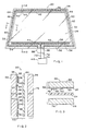
- Figures 1, 2 and 3 show a transparency 20 which includes an outboard glass sheet 22, a plastic interlayer 24 (shown only in Figures 2 and 3) which may be polyvinyl butyral as is commonly used for laminated windshields or other suitable interlayer material, and an inboard glass sheet 26 (shown only in Figures 2 and 3).
- An electroconductive coating 28 is preferably placed on the surface of the transparency 20 that is not exposed, most preferably on the inboard surface 30 of the outboard glass sheet 22.
- Various coatings may exhibit the combination of transparency and electroconductivity required to serve as the heating element for the transparency 20, but a preferred coating is similar to that disclosed in U S 4,610,770 to Gillery.
- the coating comprises a silver film between a pair of zinc stannate films with a copper primer between the film layers, each of which may be applied sequentially by magnetron sputtering.
- the silver acts as the conductive layer and the zinc stannate films serve to mask the reflectance of the silver.
- the coating exhibits a surface resistivity on the glass surface 30 of approximately 7 to 8 ohms per square when the silver layer has a thickness of approximately 110 angstroms and serves to heat the transparency 20 when electric current is passed through it.
- An opaque border 32 such as but not limited to, a ceramic enamel, extends about the marginal edge of the transparency 20 to conceal the bus bars and other elements of the heating circuit when the transparency 20 is viewed from outside the vehicle in which it is installed, through glass ply 22, as will be discussed later, and preferably on surface 30 of glass ply 22.
- power is provided to the coating 28 via a bus bar and lead arrangement.
- a bottom bus bar 34 and top bus bar 36 are positioned on the border of the glass sheet 22 with inner edges 38 and 40 of the bus bars 34 and 36, respectively, entirely on the border 32 and spaced from border inner edge 42 so that the coating 28 must extend over border inner edge 42 and a border portion 44, as shown in Figure 2, to make electrical contact with the bus bars.
- the bus bar material is preferably a silver containing ceramic material.
- Electrical connection from a power source 46 to the top bus bar 36 includes leads 48 and 50.
- the leads 48 and 50 are positioned on border 32 and include conductive strips 54 and 56, respectively, extending in opposite directions along the bottom edge of the transparency 20 from a terminal area 58 (shown only in Figure 1) and side strips 60 and 62, extending along opposite side portions of the transparency 20 and connected to strips 54 and 56, respectively.
- End 64 of strip 60 and end 66 of strip 62 are electrically interconnected to the opposing ends of the top bus bar 36.
- Electrical connection to the bottom bus bar 34 may be made in a similar fashion via lead 68.
- the leads 48 and 50 are electrically insulated from the coating 28 and bottom bus bar 34 in any convenient manner, such as, for example, by limiting the coating 28 on surface 30 to that area of the glass ply 22 within a boundary area 52. Referring to Figure 2, the coating 28 extends over the bottom bus bar 34 but is spaced from the lead 48. Similarly, referring to Figure 3, the coating 28 extends over a portion of border 32 but is spaced from lead 48.
- Electrical connection from the power source 46 to the heatable windshield is preferably made along the lower edge at terminal area 58 (shown only in Figure 1) although it should be understood that the connections could be made at any edge and at any location along an edge.
- Electrical lead 70 connects the bottom bus bar lead 68 to one pole of the electrical power source 46 and leads 48 and 50 leading to the bus bar 36 may be wired in common to the opposite pole, for example, by means of a jumper wire 72 and lead 74.
- the coating 28 must extend partially over border 32, there is a potential for overheating. It has been determined that smoothness of the border material after it has been heated and fused onto the surface 30, i.e., fired, directly affects the surface resistance of the coating 28 over the border 32, and thus the ability of the coating 28 to effectively conduct current over the border 32 to the remaining portions of the coating 28 for heating the central area of the transparency 20, as well as increasing the coating temperature over the border 32. Smoothness of a surface is defined as the surface irregularities, for example, as seen under magnification by a scanning electron microscope. Referring to Figure 2, the coating 28 is applied over portion 44 of the border 32 between the bus bars 34, 36 and glass sheet surface 30.
- a rough border surface increases the surface resistance of the coating 28 over the portion 44, i.e., the surface resistance of the coating 28 over portion 44 of the border 32 is higher than the surface resistance of the coating 28 on the glass surface 30.
- the portion of the coating 28 over portion 44 restricts current flow and becomes hotter than the remaining portions of the coating 28 which, in turn, may lead to overheating and possible damage to the transparency 20.
- the reduced current diminishes the effectiveness of the coating 28's heating capability within the border 32. It is believed that this increases in surface resistance over a rough surface is due to the requirement of a coating to conform to the surface of a border during the coating operation.
- the smoothness of the border 32 should be such that any increase in the surface resistance of the coating 28 over the border 32 is minimized.
- an increase in surface resistance of the coating 28 over border portion 44 of about 50% or less than the surface resistance of the coating 28 covering surface 30 provides acceptable heating of the transparency 20.
- the surface resistance increase is about 20% or less which provides a more uniform heating of the transparency 20, i.e. reduces the chances for high temperature "hot spots" along the ceramic border 32 and reduces the potential for thermally induced breakage.
- the surface smoothness of the border 32 can be increased by heating it at a sufficiently high temperature and for a sufficient length of time to ensure adequate melting of all its materials.
- prolonged exposure to excessive heat will cause optical distortion to the glass sheet, e.g., roll ripple, making it unusable as a vehicle transparency.
- a major concern in determining the proper border material for the transparency 20 requires that the border material have a sufficient smoothness prior to applying coating 28 so as to reduce the coating's surface resistance increase over the border portion 44 and thus reduce overheating of the coating on the border 32 and allow adequate current flow to the coating 28, as well as providing a material that can be fired to produce the necessary smoothness at temperature and time parameters that do not adversely affect the optical properties of the glass sheet. It would be obvious to one skilled in the art that as the firing time increases, required temperature can be reduced. However, from a production standpoint, it is more advantageous to minimize the heating time to maximize output.
- gloss the measure of the surface reflectance, or gloss
- a glossmeter which measures specular reflectance off a surface and compares it to a standard base-line reflection level.
- glossmeter One type of glossmeter that may be used to measure surface smoothness, in terms of gloss units, is a Glossgard® glossmeter available from Gardner Laboratory Division of Pacific Scientific, Maryland, which measures gloss based on ASTM D 523 testing procedures and standards.
- bleed-through Another problem experienced when bus bar material is placed over the border 32 is what is commonly referrred to as "bleed-through" which occurs when the silver ions in the bus bar material migrate into, i.e. stain, the ceramic enamel border 32 and/or glass sheet 22 during heating so that there is a discoloration when viewing the transparency 20 from the outside through glass sheet 22. This condition is particularly noticeable when the border 32 is a conventional windshield border enamel which is typically applied to surface 76 of glass sheet 26.
- bleed-through can be reduced by using tempering enamels which are enamels that can better survive exposure to high temperatures and in particular to glass sheet bending temperatures and do not become too soft or fluid during firing of the bus bars or during bending of the glass plies. Bleed-through is further reduced by drying the border material immediately after application and/or by firing the ceramic border material prior to applying the bus bar material to establish a hard ceramic barrier between the materials. It should be noted that subsequent heating of the border enamel such as during firing of the bus bar material will increase the gloss of the ceramic border. However, repeated firing of the transparency tends to increase the stressed in the glass/ceramic/bus bar cross-section due to repeated thermal cycling and the mismatch of the coefficient of expansion between the bus bar and the glass/ceramic layer, as will be discussed later.
- bus bar materials with reduced amounts of frit can be used and/or the materials can be heated to lower temperatures.
- the stresses at the bus bar and glass/ceramic interface are also affected by the rigidity of the bus bar.
- An increase in the bus bar thickness and/or the amount of frit in the bus bar material will increase the structural rigidity of the bus bar and further increase the stress at the interface due to differential expansion.
- the border 32 enamel In order to provide a transparency 20 with acceptable optical quality that completely hides the bus bars and leads, the border 32 enamel must be one that can be bonded onto the glass ply 22 in a sufficiently short time such that the optics of the glass ply 22 are not degraded due to excessive or prolonged heating while at the same time, require a sufficiently high firing temperature such that the enamel will not become overly soft and/or fluid when subjected to elevated temperatures during subsequent processing, for example, bending of the glass sheet.
- the surface of enamel must also be capable of providing the necessary smoothness required to maintain any increase in coating 28 surface resistance within the range as discussed earlier.
- the enamel must resist discoloration resulting from bleed through of the bus bars.
- the glass strength of the transparency 20 should be sufficiently high so as to minimize any cracking of the transparency 20 due to the mismatch of the coefficient of thermal expansion between the bus bar material and the border enamel and glass.
- the border material is a lead borosilicate tempering enamel, such as O. Hommel 42-841 and 43-000 enamel, available from O. Hommel Corporation, Pennsylvania.
- a coating 28 which has a surface resistance on surface 30 of approximately 7 to 8 ohms per square, as discussed earlier, it has been found that a measured gloss reading of about 10 gloss units or greater on border portion 44 for these enamels, using a 60° Glossgard® glossmeter, calibrated to a black standard, provides an acceptable surface resistance increase of 1.4 ohms per square or less, with higher gloss readings providing less surface resistance increase.
- the bus bar material is preferably a low frit content, silver-containing ceramic material containing approximately 80-90% silver and 1-3% frit, by weight, and a suitable carrying medium. In one particular embodiment of the invention, the bus bar material is 84% silver and 1 1/2% frit, by weight.
- This bus bar and border material combination completely hides the bus bars 34 and 36 and leads 48 and 50 when viewing the transparency 20 from the outside, i.e., through outer ply 22, while providing the required glass strength and maintaining the surface resistance of the coating 28 over the border 32 within acceptable limits.
- the border 32 is applied to surface 30 of the glass sheet 22 in any convenient manner such as, for example, screen printing and fused to the glass surface 30 by firing the glass at a temperature between 593°C and 621°C (1100 and 1150° F), for approximately two to three minutes.
- the bus bar material is applied over the border 32 in any convenient manner such as, for example, screen printing, and the bus bar material is dried and then fired on the border 32 at a temperature between (1100°F to 1125°F) 593°C to 607°C for approximately 2 to 3 minutes.
- the glass sheet 22 and 26 may be shaped in any convenient manner as is known in the art.
- the sheets may be individually shaped by a press bending operation as described in US-A- 4,666,492 to Thimons et al or the glass sheets may be shaped together on a bending iron (not shown) by gravity sag bending and/or pressing as disclosed in US -A- 4,265,650 to Reese et al.
- glass sheet 22 is covered with a removable parting medium e.g., talc, that prevents sticking of the glass sheet, ceramic border, bus bars, and leads with an overlying glass sheet.
- a removable parting medium e.g., talc
- the glass sheet 22 is matched with corresponding glass sheet 26 which has a peripheral configuration slightly smaller than that of outer glass ply 22, so that after the glass sheets are shaped, the edges of the bent glass sheets which form the transparency 20 are aligned. It is believed that the combination of the parting medium and the bus bar and lead configuration prevents the glass sheets 22 and 26 from sticking during the shaping operation. In particular, the bus bars and leads act as a spacer which separates the glass surfaces in the vicinity of the ceramic band.
- the glass sheets are separated, the parting medium is removed and coating 28 is applied to surface 30 of glass sheet 22 in any convenient manner well known in the art, such as that disclosed in U S -A- 4,610,770.
- the transparency 20 is assembled, placing interlayer sheet 24 between the bent glass sheets 22 and 26 and laminating the assembly into a unitary structure, in any convenient manner well known in the art.
- the present invention provides a heatable transparency and in particular a heatable windshield that completely hides the bus bars and leads behind a ceramic enamel border when viewing the windshield through its outer glass ply while at the same time providing acceptable optics.
- the materials used in the ceramic enamel border and bus bars are matched so as to minimize the potential for glass cracking in the area of the border and overlaying bus bars due to stresses resulting from the differences in the coefficient of thermal expansion of the materials at the bus bar and glass/ceramic border interface.
- Surface resistance of the electroconductive coating over the ceramic border is maintained at a level that will provide acceptable heating of the transparency when electric current passes through the heating coating.
Landscapes
- Surface Heating Bodies (AREA)
- Refrigerator Housings (AREA)
Applications Claiming Priority (4)
| Application Number | Priority Date | Filing Date | Title |
|---|---|---|---|
| US267402 | 1981-05-26 | ||
| US07/267,402 US4902875A (en) | 1988-11-04 | 1988-11-04 | Power discontinuity sensor for a dual feed heatable windshield |
| US07/290,225 US5414240A (en) | 1988-12-27 | 1988-12-27 | Electrically heatable transparency |
| US290225 | 1988-12-27 |
Publications (3)
| Publication Number | Publication Date |
|---|---|
| EP0367209A2 true EP0367209A2 (fr) | 1990-05-09 |
| EP0367209A3 EP0367209A3 (fr) | 1990-08-29 |
| EP0367209B1 EP0367209B1 (fr) | 1998-08-26 |
Family
ID=26952423
Family Applications (1)
| Application Number | Title | Priority Date | Filing Date |
|---|---|---|---|
| EP89120158A Expired - Lifetime EP0367209B1 (fr) | 1988-11-04 | 1989-10-31 | Vitre chaffante chauffée électriquement |
Country Status (3)
| Country | Link |
|---|---|
| EP (1) | EP0367209B1 (fr) |
| DE (1) | DE68928797T2 (fr) |
| ES (1) | ES2121735T3 (fr) |
Cited By (2)
| Publication number | Priority date | Publication date | Assignee | Title |
|---|---|---|---|---|
| US5911899A (en) * | 1995-06-15 | 1999-06-15 | Mitsui Chemicals, Inc. | Corrosion-proof transparent heater panels and preparation process thereof |
| WO2019175781A1 (fr) * | 2018-03-12 | 2019-09-19 | Agp America S.A. | Stratifié chauffé à esthétique améliorée |
Families Citing this family (3)
| Publication number | Priority date | Publication date | Assignee | Title |
|---|---|---|---|---|
| DE10016399A1 (de) * | 1999-09-30 | 2001-04-12 | Inglas Innovative Glassysteme | Vorrichtung zur Halterung von Glasscheiben |
| DE10055162B4 (de) * | 2000-11-08 | 2013-07-18 | Bayerische Motoren Werke Aktiengesellschaft | Schutzscheibe für Außenleuchten eines Kraftfahrzeugs |
| CN105338672A (zh) * | 2015-09-17 | 2016-02-17 | 福建省万达汽车玻璃工业有限公司 | 一种可均匀电加热的汽车夹层玻璃 |
Citations (4)
| Publication number | Priority date | Publication date | Assignee | Title |
|---|---|---|---|---|
| EP0025755A1 (fr) * | 1979-09-08 | 1981-03-25 | Saint Gobain Vitrage International | Vitrage chauffant à film résistant mince |
| US4654067A (en) * | 1986-01-28 | 1987-03-31 | Ford Motor Company | Method for making an electrically heatable windshield |
| US4725710A (en) * | 1985-11-07 | 1988-02-16 | Ford Motor Company | Electrically heatable vision unit |
| WO1988006095A1 (fr) * | 1987-02-17 | 1988-08-25 | Libbey-Owens-Ford Co. | Procede de production d'un ensemble-fenetre chauffe electriquement, et article ainsi obtenu |
-
1989
- 1989-10-31 ES ES89120158T patent/ES2121735T3/es not_active Expired - Lifetime
- 1989-10-31 EP EP89120158A patent/EP0367209B1/fr not_active Expired - Lifetime
- 1989-10-31 DE DE68928797T patent/DE68928797T2/de not_active Expired - Fee Related
Patent Citations (4)
| Publication number | Priority date | Publication date | Assignee | Title |
|---|---|---|---|---|
| EP0025755A1 (fr) * | 1979-09-08 | 1981-03-25 | Saint Gobain Vitrage International | Vitrage chauffant à film résistant mince |
| US4725710A (en) * | 1985-11-07 | 1988-02-16 | Ford Motor Company | Electrically heatable vision unit |
| US4654067A (en) * | 1986-01-28 | 1987-03-31 | Ford Motor Company | Method for making an electrically heatable windshield |
| WO1988006095A1 (fr) * | 1987-02-17 | 1988-08-25 | Libbey-Owens-Ford Co. | Procede de production d'un ensemble-fenetre chauffe electriquement, et article ainsi obtenu |
Cited By (2)
| Publication number | Priority date | Publication date | Assignee | Title |
|---|---|---|---|---|
| US5911899A (en) * | 1995-06-15 | 1999-06-15 | Mitsui Chemicals, Inc. | Corrosion-proof transparent heater panels and preparation process thereof |
| WO2019175781A1 (fr) * | 2018-03-12 | 2019-09-19 | Agp America S.A. | Stratifié chauffé à esthétique améliorée |
Also Published As
| Publication number | Publication date |
|---|---|
| EP0367209B1 (fr) | 1998-08-26 |
| EP0367209A3 (fr) | 1990-08-29 |
| DE68928797T2 (de) | 1999-04-08 |
| ES2121735T3 (es) | 1998-12-16 |
| DE68928797D1 (de) | 1998-10-01 |
Similar Documents
| Publication | Publication Date | Title |
|---|---|---|
| US5414240A (en) | Electrically heatable transparency | |
| US4786784A (en) | Method for producing an electrically heated window assembly and resulting article | |
| US5099105A (en) | Electrically heated automobile glazing with electrically conductive decorative frame | |
| US7205504B2 (en) | Interlayer composite for a laminated transparency | |
| US5270517A (en) | Method for fabricating an electrically heatable coated transparency | |
| US4820902A (en) | Bus bar arrangement for an electrically heated transparency | |
| CN101454154B (zh) | 窗玻璃 | |
| CA2054634C (fr) | Bornes de connecteurs electriques pour fenetres de vehicules chauffees electriquement | |
| US8299400B2 (en) | Heatable vehicle window utilizing silver inclusive epoxy electrical connection and method of making same | |
| WO2006041644A1 (fr) | Fenetre de vehicule comprenant une ou plusieurs barres omnibus de fritte noire conductrice | |
| JPH0280353A (ja) | 導電性コーティングを有するガラス板及びその製造方法 | |
| EP1216147B1 (fr) | Vitrage | |
| EP3468794B1 (fr) | Vitrage chauffant | |
| EP0367209B1 (fr) | Vitre chaffante chauffée électriquement | |
| JPH09323374A (ja) | 薄層積重体 | |
| US20230049243A1 (en) | Glazing having a coated print portion, method of manufacturing the same and use of the same | |
| GB2352998A (en) | Laminated window | |
| CN115956397A (zh) | 可加热的运载工具装配玻璃 | |
| EP0406746A2 (fr) | Joint d'étanchéité pour pare-brise chauffant |
Legal Events
| Date | Code | Title | Description |
|---|---|---|---|
| PUAI | Public reference made under article 153(3) epc to a published international application that has entered the european phase |
Free format text: ORIGINAL CODE: 0009012 |
|
| AK | Designated contracting states |
Kind code of ref document: A2 Designated state(s): BE DE ES FR GB IT SE |
|
| PUAL | Search report despatched |
Free format text: ORIGINAL CODE: 0009013 |
|
| AK | Designated contracting states |
Kind code of ref document: A3 Designated state(s): BE DE ES FR GB IT SE |
|
| 17P | Request for examination filed |
Effective date: 19901119 |
|
| 17Q | First examination report despatched |
Effective date: 19930114 |
|
| APAB | Appeal dossier modified |
Free format text: ORIGINAL CODE: EPIDOS NOAPE |
|
| GRAG | Despatch of communication of intention to grant |
Free format text: ORIGINAL CODE: EPIDOS AGRA |
|
| GRAG | Despatch of communication of intention to grant |
Free format text: ORIGINAL CODE: EPIDOS AGRA |
|
| GRAH | Despatch of communication of intention to grant a patent |
Free format text: ORIGINAL CODE: EPIDOS IGRA |
|
| GRAH | Despatch of communication of intention to grant a patent |
Free format text: ORIGINAL CODE: EPIDOS IGRA |
|
| GRAA | (expected) grant |
Free format text: ORIGINAL CODE: 0009210 |
|
| AK | Designated contracting states |
Kind code of ref document: B1 Designated state(s): BE DE ES FR GB IT SE |
|
| ITF | It: translation for a ep patent filed | ||
| REF | Corresponds to: |
Ref document number: 68928797 Country of ref document: DE Date of ref document: 19981001 |
|
| ET | Fr: translation filed | ||
| REG | Reference to a national code |
Ref country code: ES Ref legal event code: FG2A Ref document number: 2121735 Country of ref document: ES Kind code of ref document: T3 |
|
| PLBE | No opposition filed within time limit |
Free format text: ORIGINAL CODE: 0009261 |
|
| STAA | Information on the status of an ep patent application or granted ep patent |
Free format text: STATUS: NO OPPOSITION FILED WITHIN TIME LIMIT |
|
| RAP2 | Party data changed (patent owner data changed or rights of a patent transferred) |
Owner name: PPG INDUSTRIES OHIO, INC. |
|
| 26N | No opposition filed | ||
| REG | Reference to a national code |
Ref country code: FR Ref legal event code: TP |
|
| REG | Reference to a national code |
Ref country code: GB Ref legal event code: 732E |
|
| REG | Reference to a national code |
Ref country code: GB Ref legal event code: IF02 |
|
| PGFP | Annual fee paid to national office [announced via postgrant information from national office to epo] |
Ref country code: SE Payment date: 20021003 Year of fee payment: 14 |
|
| PGFP | Annual fee paid to national office [announced via postgrant information from national office to epo] |
Ref country code: GB Payment date: 20021023 Year of fee payment: 14 |
|
| PG25 | Lapsed in a contracting state [announced via postgrant information from national office to epo] |
Ref country code: GB Free format text: LAPSE BECAUSE OF NON-PAYMENT OF DUE FEES Effective date: 20031031 |
|
| PG25 | Lapsed in a contracting state [announced via postgrant information from national office to epo] |
Ref country code: SE Free format text: LAPSE BECAUSE OF NON-PAYMENT OF DUE FEES Effective date: 20031101 |
|
| GBPC | Gb: european patent ceased through non-payment of renewal fee |
Effective date: 20031031 |
|
| EUG | Se: european patent has lapsed | ||
| PGFP | Annual fee paid to national office [announced via postgrant information from national office to epo] |
Ref country code: FR Payment date: 20041020 Year of fee payment: 16 |
|
| PGFP | Annual fee paid to national office [announced via postgrant information from national office to epo] |
Ref country code: ES Payment date: 20041110 Year of fee payment: 16 |
|
| PGFP | Annual fee paid to national office [announced via postgrant information from national office to epo] |
Ref country code: BE Payment date: 20041125 Year of fee payment: 16 |
|
| PGFP | Annual fee paid to national office [announced via postgrant information from national office to epo] |
Ref country code: DE Payment date: 20041130 Year of fee payment: 16 |
|
| APAH | Appeal reference modified |
Free format text: ORIGINAL CODE: EPIDOSCREFNO |
|
| PG25 | Lapsed in a contracting state [announced via postgrant information from national office to epo] |
Ref country code: IT Free format text: LAPSE BECAUSE OF NON-PAYMENT OF DUE FEES;WARNING: LAPSES OF ITALIAN PATENTS WITH EFFECTIVE DATE BEFORE 2007 MAY HAVE OCCURRED AT ANY TIME BEFORE 2007. THE CORRECT EFFECTIVE DATE MAY BE DIFFERENT FROM THE ONE RECORDED. Effective date: 20051031 Ref country code: BE Free format text: LAPSE BECAUSE OF NON-PAYMENT OF DUE FEES Effective date: 20051031 |
|
| PG25 | Lapsed in a contracting state [announced via postgrant information from national office to epo] |
Ref country code: ES Free format text: LAPSE BECAUSE OF NON-PAYMENT OF DUE FEES Effective date: 20051102 |
|
| PG25 | Lapsed in a contracting state [announced via postgrant information from national office to epo] |
Ref country code: DE Free format text: LAPSE BECAUSE OF NON-PAYMENT OF DUE FEES Effective date: 20060503 |
|
| PG25 | Lapsed in a contracting state [announced via postgrant information from national office to epo] |
Ref country code: FR Free format text: LAPSE BECAUSE OF NON-PAYMENT OF DUE FEES Effective date: 20060630 |
|
| REG | Reference to a national code |
Ref country code: FR Ref legal event code: ST Effective date: 20060630 |
|
| REG | Reference to a national code |
Ref country code: ES Ref legal event code: FD2A Effective date: 20051102 |
|
| BERE | Be: lapsed |
Owner name: *PPG INDUSTRIES OHIO INC. UNE SOCIETE DE L'ETAT DE Effective date: 20051031 |