EP0367116A1 - Gerät zur Stosswellen-Behandlung - Google Patents
Gerät zur Stosswellen-Behandlung Download PDFInfo
- Publication number
- EP0367116A1 EP0367116A1 EP89119924A EP89119924A EP0367116A1 EP 0367116 A1 EP0367116 A1 EP 0367116A1 EP 89119924 A EP89119924 A EP 89119924A EP 89119924 A EP89119924 A EP 89119924A EP 0367116 A1 EP0367116 A1 EP 0367116A1
- Authority
- EP
- European Patent Office
- Prior art keywords
- image
- ultrasonic wave
- doppler
- timing
- shock wave
- Prior art date
- Legal status (The legal status is an assumption and is not a legal conclusion. Google has not performed a legal analysis and makes no representation as to the accuracy of the status listed.)
- Granted
Links
Images


Classifications
-
- A—HUMAN NECESSITIES
- A61—MEDICAL OR VETERINARY SCIENCE; HYGIENE
- A61B—DIAGNOSIS; SURGERY; IDENTIFICATION
- A61B17/00—Surgical instruments, devices or methods, e.g. tourniquets
- A61B17/22—Implements for squeezing-off ulcers or the like on the inside of inner organs of the body; Implements for scraping-out cavities of body organs, e.g. bones; Calculus removers; Calculus smashing apparatus; Apparatus for removing obstructions in blood vessels, not otherwise provided for
- A61B17/225—Implements for squeezing-off ulcers or the like on the inside of inner organs of the body; Implements for scraping-out cavities of body organs, e.g. bones; Calculus removers; Calculus smashing apparatus; Apparatus for removing obstructions in blood vessels, not otherwise provided for for extracorporeal shock wave lithotripsy [ESWL], e.g. by using ultrasonic waves
- A61B17/2256—Implements for squeezing-off ulcers or the like on the inside of inner organs of the body; Implements for scraping-out cavities of body organs, e.g. bones; Calculus removers; Calculus smashing apparatus; Apparatus for removing obstructions in blood vessels, not otherwise provided for for extracorporeal shock wave lithotripsy [ESWL], e.g. by using ultrasonic waves with means for locating or checking the concrement, e.g. X-ray apparatus, imaging means
Definitions
- the present invention relates to a shock wave treatment apparatus for a treatment such as disintegration of an object such as a cancer, a concretion or the like present within a living body by concentrating shock waves on the object located in a focal region or point.
- a shock wave generator 1 for destruction or disintegration of a concretion or the like within a living body, as disclosed in Japanese Patent Laid-Open Specification No. 62-49843.
- a shock wave transducer 2 having a spherical concave front surface of a certain curvature includes a central through hole 2a of a certain shape, and the transducer 2 is supported by a backing member 3 adhered to the back surface of the transducer 2.
- a ultrasonic wave probe 4 for scanning the living body to obtain a B-mode section image or the like is provided with a ultrasonic wave transmitting-receiving surface or arrey 4a in its one end, and the arrey 4a is located in the same spherical surface or a retracted position as or from the front surface of the transducer 2.
- the shock wave generator 1 is contacted to a living body 6 via a water bag 5 containing water therein.
- a concentration point positioning is required. That is, the concentration point of the shock waves generated by the transducer 2 is adjusted to coincide with the concretion.
- This concentration point positioning is effected by displaying a B-mode section image of the living body and a target mark representing the concentration point of the shock waves on the display and by allowing the target mark to coincide with the concretion on the display.
- the target mark is geometrically determined depending on the ultrasonic wave generator 1.
- the target mark in the B-mode image is geometrically determined depending on the generator, and the actual concentration point of the shock waves generated by the transducer is often somewhat different or shifted from the target mark.
- the actual concentration point of the shock waves can not be confirmed.
- it is also difficult to confirm the results of the shock wave generation for instance, a disintegrated or not disintegrated state and the extent and appearance of the disintegration of the concretion and the like.
- a shock wave treatment apparatus comprising means for generating a shock wave toward a living body having an object to be disintegrated by the shock wave, a ultrasonic wave probe for transmitting a ultrasonic wave toward the living body or receiving a ultrasonic wave echo from the living body, means for forming a B-mode section image of the living body on the basis of the ultrasonic wave echo, means for obtaining a ultrasonic wave doppler alteration frequency from the ultrasonic wave echo and for performing a color flow mapping process on the basis of the ultrasonic wave doppler alteration frequency to form a color flow mapping image of the living body, and means for displaying at least one of the B-mode section image and the color flow mapping image.
- a shock wave treatment apparatus comprising means for generating a shock wave toward a living body having an object to be disintegrated by the shock wave, a ultrasonic wave probe for transmitting a ultrasonic wave toward the living body or receiving a ultrasonic wave echo from the living body, means for performing a phase detection of the ultrasonic wave echo to obtain doppler information, and means for reproducing sound from the doppler information.
- Fig. 2 a first embodiment of a shock wave treatment apparatus according to the present invention.
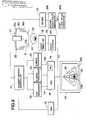
- a shock wave generator 16 includes a shock wave transducer 16a having a spherical concave surface for generating shock waves therefrom and a water bag 16b having flexible bellows 16c for performing an effective transmission of the shock waves to a living body P, for instance, in order to disintegrate a concretion 31 of an object 32 such as a kidney or the like.
- the shock wave transducer 16a is formed with a central hole therein.
- various devices such as a vibrator of a concave semisphere form, an electromagnetic induction type sound source composed of a combination of a spiral coil and a metal membrane arranged close thereto, and the like can be applied to the shock wave transducer 16a.
- a ultrasonic wave probe 17 having a ultrasonic wave transmitting-receiving surface or arrey 17a in its end is arranged in the central hole portion of the shock wave transducer 16a.
- the ultrasonic wave probe 17 transmits a ultrasonic wave toward the living body P and receives a ultrasonic wave echo therefrom to effect a scanning of the living body P for obtaining a B-mode section image, a CFM (color flow mapping) image and an M-mode image.
- a timing controller 20 outputs a shock wave generation timing signal to a delay counter 19 and a pulser 21.
- the pulser 21 sends a drive signal to the shock wave transducer 16a in order to drive the same, and its driving timing is controlled by the shock wave generation timing signal fed from the timing controller 20.
- the delay counter 19 outputs a delayed pulse DP to an RPG (rate pulse generator) timing delayed by a certain period of time after the shock wave generation timing.
- the delay timing of the delayed pulse DP ouput by the delay counter 19 is controlled by a delay timing set 18.
- the RPG 10 generates a delayed frame pulse DFP to a transmit-receive controller 11 and a DSC (digital scan converter) 14 in synchronization with the delayed pulse DP output from the delay counter 19.
- the transmit-receive controller 11 controls the ultrasonic wave probe 17 to transmit or receive the ultrasonic wave to or from the living body P.
- the transmit-receive controller 11 comprises a transmitter and a receiver.
- the transmitter includes a transmission delay device for setting a certain delay time for the transmission of the delayed frame pulse and a pulser for generating a pulse for driving the alley 17a of the ultrasonic wave probe 17 in synchronization with the delay time given by the transmission delay device.
- the receiver includes a preamplifier for amplifying a ultrasonic wave echo received by the ultrasonic wave probe 17, a receipt delay device for setting a certain delay time for the output of the amplified ultrasonic wave echo, and an adder for adding the delayed echoes.
- a B-mode processor 12 includes a detector for performing an amplitude detection of an output addition signal of the transmit-receive controller 11, and an A/D (analog-digital) converter for converting the amplitude detected signal to a digital detected signal to obtain a monochrome B-mode section image.
- the operated results of the B-mode processor 12 are sent to the DSC 14.
- a CFM (color flow mapping) processor 13 includes a phase detector for effecting a phase detection of the ultrasonic wave echo, an MTI (moving target indication) filter for removing a clatter component of the output signal of the phase detector, a self correlator for performing a self correlation of the output signal of the MTI to obtain a ultrasonic wave doppler alteration frequency, and a processor for operating an average speed and a power of a moving object according to the ultrasonic wave doppler alteration frequency to obtain a CFM (color flow mapping) image. That is, the CFM processor 13 performs the color flow mapping process to obtain a CFM image. The obtained result of the CFM processor 13 is fed to the DSC 14.
- the DSC 14 is provided with a frame memory (FM) 14a, in which the scan conversion between the sampling and display systems is carried out.
- the writing timing of the data into the FM 14a of the DSC 14 is determined by the delayed frame pulse DFP output from the RPG 10.
- the data of the B-mode section image and the CFM image is stored in the FM 14a of the DSC 14.
- the scan conversion result in the DSC 14 is fed to a color display 15. On the color display 15, the monochrome B-mode section image 15a and the CFM image 15b overlapped thereon are reproduced.
- a large pressure such as several 100 to 1000 bar is caused at the concentration point.
- the object 31 receives a large pressure and is moved in a direction F. Then, after the shock wave 33 passes through the object 31, the object 31 is pulled back by a negative pressure component the shock wave 33 trails in the reverse direction F′ to the direction F, as shown in Fig. 4. Thus, the object 31 performs damped oscillation.
- the object 31 When the object 31 is not disintegrated by the shock wave 33, the object 31 performs damped oscillation while the object 31 retains its original form.
- the disintegrated pieces of the object are moved in all directions depending on their relative positions with respect to the concentration point of the shock wave and the surrounding conditions thereof.
- the behavior of the disintegrated pieces can be observed by transmitting a ultrasonic wave to a certain region containing the disintegrated pieces, obtaining frequency alteration information of the ultrasonic wave and analyzing the obtained frequency alteration information.
- a ultrasonic wave doppler alteration frequency of a ultrasonic wave is obtained from a received ultrasonic wave echo, and a CFM (color flow mapping) process is effected on the basis of the ultrasonic wave doppler alteration frequency.
- the result of the CFM process is overlapped on a B-mode section image on a display, and this is used as a monitory image during a shock wave treatment, as hereinafter described in detail.
- the ultrasonic wave probe 17 effects the transmission and receipt of the ultrasonic wave to and from the living body P by the transmit-receive controller 11, and the transmit-receive controller 11 obtains the ultrasonic wave echo.
- the B-mode processor 12 outputs the result of the B-mode process to the DSC 14, and the B-mode section image 15a of the living body P is formed in the FM 14a of the DSC 14. Then, the data of the B-mode section image 15a is read out of the FM 14a and is sent to the display 15 to display the B-mode section image 15a thereon.
- the shock wave transducer 16a When the shock wave transducer 16a is driven by sending the shock wave generation timing signal to the pulser 21, the shock wave transducer 16a generates the shock waves to concentrate on the concretion 31 of the object such as the kidney in the living body P.
- the ultrasonic wave doppler alteration frequency in the living body P is operated from the ultrasonic wave echo obtained by the transmit-receive controller 11, and the CFM process is carried out on the basis of the ultrasonic wave doppler alteration frequency.
- the resulted data of the CFM process is fed to the DSC 14, and the CFM image is formed in the FM 14a of the DSC 14.
- the CFM image is mixed with the monochrome B-mode action image, and the monochrome B-mode section image and the CFM image overlapped thereon are displayed on the display 15.
- the writing of the data of the B-mode section image and the CFM image into the FM memory 14a of the DSC 14 with respect to the shock wave generation operation is performed as follows.
- the delayed frame pulse DFP is fed from the RPG 10 to the DSC 14 at the timing delayed by the predetermined period of time after the timing of the shock wave generation.
- the DSC 14 is started to store the data into the FM 14a at the timing of input of the delayed frame pulse DFP, and, when one frame of the data is stored in the FM 14a, the storing of the data is stopped. This step is repeated every input of the delayed frame pulse DFP into the DSC 14 or every shock wave generation in the shock wave transducer 16a.
- the data writing timing by the delayed frame pulse DFP or the delayed pulse DP can be freely determined by the delay timing set 18, as described above.
- the reproducing and displaying of the still picture images such as the B-mode section image and the CFM image can be carried out at the best timing so that the best mode of the shock wave concentration positioning, the shock wave generation results and the disintegration state of the concretion or the like can be readily determined or adjusted and observed.
- the CFM image display is effected as follows.
- the doppler signal of the concretion is larger with respect to that of the other tissue, particularly, the surrounding tissue, and hence the position of the concretion can be readily confirmed in the CFM image 15b by generating relatively weak shock waves during the positioning of the concretion. Also, even when the strong shock waves are generated in order to disintegrate the concretion after the positioning of the concretion, the concretion is moved larger than the tissue because of the acoustic impedance difference, and hence the position of the concretion can be easily confirmed in the CFM image 15b.
- the tissue is deformed and moved, and this is appeared in the CFM image 15b.
- the concentration region or point of the actually generated shock waves can be easily confirmed in the CFM image 15b.
- the moving condition of the concretion against the shock waves is different, it is readily known whether the concretion is disintegrated or not.
- the sizes, moving directions and degree of dispersion of the disintegrated concretion pieces can be readily confirmed in the CFM image 15b by the extent of color mixture and the hue variation.
- the position of the object such as the concretion within the living body can be readily confirmed, and the position of the concentration point of the actual shock waves can be readily confirmed on the display.
- the positioning of the concentration point of the actual shock waves on the object can be readily performed.
- the shock wave generation results of the object and extent and state of the disintegrated pieces of the object can be readily confirmed on the display. Therefore, the time and accuracy of the positioning of the concretion and the positioning of the shock waves on the concretion can be largely improved, and ineffective operations and operator's burden can be largely reduced.
- Fig. 6 there is shown a second embodiment of a shock wave treatment apparatus according to the present invention, having a similar structure to the first embodiment shown in Fig. 2, except an M-mode processor 22 for obtaining an M-mode image is also included.
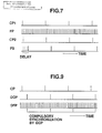
- a first clock pulse generator 20a outputs a first clock pulse CP1 to a second clock pulse generator 20b.
- An RPG (rate pulse generator) 10 outputs a rate pulse as a frame pulse FP to a transmit-receive controller 11, a DSC (digital scan converter) 14 and the second clock pulse generator 20b.
- the second clock pulse generator 20b outputs a second clock pulse CP2 having the same interval as that of the first clock pulse CP1 as a shock wave generation timing signal to a delay counter 19 and a pulser 21 in synchronization with the frame pulse FP output from the RPG 10.
- the delay counter 19 outputs a freeze signal FS at a timing delayed by a certain period of time after the shock wave generation timing in synchronization with the frame pulse FP.
- Fig. 7 there are schematically shown the first clock pulse CP1, the frame pulse FP, the second clock pulse CP2 and the freeze signal FS.
- the delay timing of the freeze signal FS output from the delay counter 19 is controlled to determine to integral number times as much as the interval of the frame pulse FP by a delay timing set 18.
- the M-mode processor 22 includes a detector for performing an amplitude detection of an output addition signal of the transmit-receive controller 11, and an A/D (analog-digital) converter for converting the amplitude detected signal to a digital detected signal to obtain a monochrome M-mode image.
- the operated results of the M-mode processor 22 are sent to the DSC 14.
- a CFM processor 13 performs the CFM process in both the B mode and M-mode imagings.
- the CFM processor 13 can discriminate between the B-mode and M-mode image signals and mix or overlap the monochrome B-mode or M-mode image signals and the CFM signals to obtain the B-mode and M-mode images, as shown in Fig. 10.
- doppler signals are picked up from the ultrasonic wave echo and are processed with respect to only a certain direction such as, in practice, a shock wave concentration point direction d , as shown in Fig. 10a, in a depth of the living body P to obtain the M-mode image.
- a shock wave concentration point direction d as shown in Fig. 10a
- Fig. 10b One example of the M-mode image is shown in Fig. 10b.
- the M-mode image can be utilized.
- the doppler signals are processed over a certain area to display the CFM image on the display.
- the reproduceable number of the frame images per second is approximately 10, which may be somewhat varied depending on the various conditions.
- the doppler signals are operated only along one direction such as, in practice, the direction the shock wave concentration point is positioned, and thus a much more number of the frame images can be reproduced compared with that of the CFM imaging, that is, the resolving power in unit tim can be largely improved, resulting in that the doppler signals can be observed with a high resolving power in the M-mode image.
- the writing of the data obtained in the B-mode processor 12, the CFM processor 13 and the M-mode processor 22 into the frame memory 14a of the DSC 14 with respect to the timing of the shock wave generation operation is carried out at the desired timing by using the freeze signal FS output from the delay counter 19 in a similar manner to the first embodiment described above.
- the reproducing and displaying of the still picture images can be carried out at the best timing so that the best mode of the shock wave concentration positioning, the shock wave generation results and the disintegration state of the concretion or the like can be readily determined or adjusted and observed.
- the same effects and advantages as those of the first embodiment can be obtained.
- Fig. 8 there is shown a third embodiment of a shock wave treatment apparatus according to the present invention, having a similar structure to the first and the second embodiment described above.
- a timing controller 20 outputs a clock pulse CP as a shock wave generation timing signal to a delay counter 19 and a pulser 21.
- a delay counter 19 outputs a delayed clock pulse DCP to an RPG 10 at a timing delayed by a certain period of time after a shock wave generation timing.
- the delay timing of the delayed clock pulse DCP output by the delay counter 19 is continuously controlled by a delay timing set 18.
- a timing of a delayed frame pulse DFP is controlled by the delayed clock pulse DCP fed from the delay counter 19 in order to compulsorily synchronize with the timing of the delayed clock pulse DCP.
- the clock pulse CP as the shock wave generation timing signal, the delayed clock pulse DCP and the delayed frame pulse DFP.
- the writing of the data obtained in the B-mode processor 12, the CFM processor 13 and the M-mode processor 22 into the frame memory 14a of the DSC 14 with respect to the timing of the shock wave generation operation is carried out at the desired timing by using the delayed frame pulse DFP output from the RPG 10 in a similar manner to the above described embodiments.
- the delay timing of the delayed clock pulse DCP can be continuously changed, and hence more accurate control can be performed as compared with the second embodiment described above. In this case, the same effects and advantages as those of the first and second embodiments can be obtained.
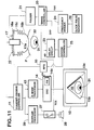
- a fourth embodiment of a shock wave treatment apparatus having a similar construction to the first embodiment described above, except that a doppler processor 29 for outputting doppler information in an audio signal form is provided.
- a timing controller 20 outputs a timing control signal TCS as a shock wave generation timing signal to a pulser 21 and a switch 27 for performing an open-close control in synchronization with the timing control signal TCS.
- a clock pulse generator 26 generates a clock pulse to a frequency divider 24 which outputs a frequency divided signal FDS to the timing controller 20.
- An RPG (rate pulse generator) 10 generates a rate pulse as a frame pulse FP to a transmit-receive controller 11, a DSC (digital scan converter) 14 and a delay circuit 23. The delay circuit 23 sets back the frame pulse FP a certain period of time and sends a delayed frame pulse DFP to the timing controller 20.
- the timing controller 20 outputs the shock wave generation timing signal TCS to the pulser 21 at a timing delayed by a desired period of time t after the timing of the frame pulse FP.
- the reproducing and displaying of the still picture images can be effected at the best timing in the same manner as described above.
- Fig. 12 there are schematically shown the frame pulse FP, the delayed frame pulse DFP, the frequency divided signal FDS and the timing control signal TCS along with on and off modes of the switch 27.
- a system controller 25 controls the operation of the whole system of the shock wave treatment apparatus.
- the writing of the data obtained in the B-mode processor 12 into a frame memory (FM) 14a with respect to the shock wave generation timing is started by the frame pulse FP fed from the RPG, and, when one frame of the data is stored in the FM 14a, the data storing is stopped. This step is repeated.
- a doppler processor 29 includes a phase detector for effecting a phase detection of a ultrasonic wave echo sent from the transmit-receive controller 11, and a processor for setting a sample gate position.
- audio signals representing doppler information in the sample gate position is picked up from the ultrasonic wave echo.
- the audio signals are fed from the doppler processor 29 to a speaker 28 via the switch 27, and the speaker 28 reproduces doppler sounds from the audio signals.
- the doppler processor 29, the speaker 28 and the switch 27 may constitute first, second and third means, respectively.
- the delay circuit 23 outputs the delayed frame pulse DFP to the timing controller 20, and the frequency divider 24 sends the frequency divided signal FDS to the timing controller 20.
- the timing controller 20 outputs the timing control signal TCS as the shock wave generation timing signal at the timing of the following delayed frame pulse DFP, i.e., in synchronization with the leading edge of the delayed frame pulse DFP.
- the shock wave transducer 16a is driven to generate the shock waves at the timing of the leading edge of the shock wave generation timing signal TCS.
- the affecting area direction or path of the shock waves can be positioned in a right hand side end portion 15c in the B-mode section image 15a, as shown in Fig. 11.
- the phase detection of the ultrasonic wave echo is effected and the doppler information is picked up in the form of the audio signals in the doppler processor 29.
- the audio signals are sent to the speaker 28 through the switch 27, and the speaker 28 reproduces the doppler sounds from the audio signals.
- the doppler information pickup is carried out by using the pulsed wave doppler method, and the doppler information in the sample gate position determined in the B-mode section image is obtained. That is, by setting the sample gate position to a portion containing the disintegrated object pieces in advance, the doppler information of or near the disintegrated object pieces can be effectively obtained.
- the continuous wave doppler method may be also applied.
- a particular vibrator for the continuous wave doppler information pickup may be provided near the ultrasonic wave probe 17.
- a part 17b of the vibrator elements of the arrey 17a of the ultrasonic wave probe 17 may be used for the continuous wave doppler information pickup only, as shown in Fig. 13.
- the switch 27 is turned off in synchronization with the shock wave generation timing signal output from the timing controller 20 to remove the shock wave components from the doppler sounds. That is, as shown in Fig. 12, the switch 27 is turned off at the timing of the leading edge of the timing control signal TCS fed from the timing controller 20 to prevent the shock wave components from mixing in the doppler sounds, with the result of clearly monitoring the doppler sounds. Further, by making the OFF period of time of the switch 27 to be variable, more accurate or precise control for removing the shock wave component can be performed.
- a CFM processor 13 and/or an M-mode processor 22 of the second embodiment may be also provided in the apparatus described above, with the result of obtaining the same effects and advantages as those of the first and second embodiments.
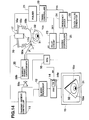
- a fifth embodiment of a shock wave treatment apparatus having the same structure as the fourth embodiment shown in Fig. 11, except a doppler phonocardiograph 30 is provided.
- the doppler phonocardiograph 30 includes a ultrasonic transmit-receive member 30a, a doppler phonocardiograph body 30b and a speaker 30c, which are coupled in series.
- the ultrasonic transmit-receive member 30a transmits a ultrasonic wave toward an object 31 such as a concretion within an internal organ such as a kidney 32 in a living body P and receives a reflected component.
- the body 30b picks up doppler information from the reflected component, and the doppler information is reproduced in the sound form by the speaker 30c.
- the body 30b and the speaker 30c may constitute first and second means, respectively.
- the body 30b includes a device for preventing shock wave components from mixing in the doppler sounds in synchronization with the shock wave generation timing signal output from the timing controller 20, this shock wave preventing device having a similar construction to that of the fourth embodiment shown in Fig. 11, with the result of clearly monitoring the doppler sounds.
- the body 30b may constitute third means. In this embodiment, the same effects and advantages as those of the fourth embodiment can be obtained.
Landscapes
- Health & Medical Sciences (AREA)
- Surgery (AREA)
- Nuclear Medicine, Radiotherapy & Molecular Imaging (AREA)
- Life Sciences & Earth Sciences (AREA)
- Biomedical Technology (AREA)
- Vascular Medicine (AREA)
- Orthopedic Medicine & Surgery (AREA)
- Engineering & Computer Science (AREA)
- Radiology & Medical Imaging (AREA)
- Heart & Thoracic Surgery (AREA)
- Medical Informatics (AREA)
- Molecular Biology (AREA)
- Animal Behavior & Ethology (AREA)
- General Health & Medical Sciences (AREA)
- Public Health (AREA)
- Veterinary Medicine (AREA)
- Ultra Sonic Daignosis Equipment (AREA)
Priority Applications (1)
| Application Number | Priority Date | Filing Date | Title |
|---|---|---|---|
| EP93100734A EP0548048B1 (de) | 1988-10-26 | 1989-10-26 | Gerät zur Stosswellen-Behandlung |
Applications Claiming Priority (4)
| Application Number | Priority Date | Filing Date | Title |
|---|---|---|---|
| JP63271456A JPH02116360A (ja) | 1988-10-26 | 1988-10-26 | 衝撃波治療装置 |
| JP271456/88 | 1988-10-26 | ||
| JP63276627A JPH02121646A (ja) | 1988-10-31 | 1988-10-31 | 衝撃波治療装置 |
| JP276627/88 | 1988-10-31 |
Related Child Applications (1)
| Application Number | Title | Priority Date | Filing Date |
|---|---|---|---|
| EP93100734.8 Division-Into | 1993-01-19 |
Publications (2)
| Publication Number | Publication Date |
|---|---|
| EP0367116A1 true EP0367116A1 (de) | 1990-05-09 |
| EP0367116B1 EP0367116B1 (de) | 1994-06-08 |
Family
ID=26549721
Family Applications (2)
| Application Number | Title | Priority Date | Filing Date |
|---|---|---|---|
| EP93100734A Expired - Lifetime EP0548048B1 (de) | 1988-10-26 | 1989-10-26 | Gerät zur Stosswellen-Behandlung |
| EP89119924A Expired - Lifetime EP0367116B1 (de) | 1988-10-26 | 1989-10-26 | Gerät zur Stosswellen-Behandlung |
Family Applications Before (1)
| Application Number | Title | Priority Date | Filing Date |
|---|---|---|---|
| EP93100734A Expired - Lifetime EP0548048B1 (de) | 1988-10-26 | 1989-10-26 | Gerät zur Stosswellen-Behandlung |
Country Status (3)
| Country | Link |
|---|---|
| US (1) | US5174294A (de) |
| EP (2) | EP0548048B1 (de) |
| DE (2) | DE68915935T2 (de) |
Cited By (3)
| Publication number | Priority date | Publication date | Assignee | Title |
|---|---|---|---|---|
| EP0511506A1 (de) * | 1991-04-26 | 1992-11-04 | Dornier Medizintechnik Gmbh | Vorrichtung zur Fokalbereichsortung für die Lithotripsie |
| DE4446192A1 (de) * | 1994-12-23 | 1996-07-04 | Wolf Gmbh Richard | Verfahren zur Trefferkontrolle |
| WO1997003610A1 (de) * | 1995-07-21 | 1997-02-06 | Fraunhofer-Gesellschaft zur Förderung der angewandten Forschung e.V. | Vorrichtung zur detektion von konkrementen und kavitationsblasen |
Families Citing this family (27)
| Publication number | Priority date | Publication date | Assignee | Title |
|---|---|---|---|---|
| US5435311A (en) * | 1989-06-27 | 1995-07-25 | Hitachi, Ltd. | Ultrasound therapeutic system |
| DE4241161C2 (de) * | 1992-12-07 | 1995-04-13 | Siemens Ag | Akustische Therapieeinrichtung |
| JPH06209941A (ja) * | 1993-01-18 | 1994-08-02 | Toshiba Corp | 超音波診断装置 |
| DE4302537C1 (de) * | 1993-01-29 | 1994-04-28 | Siemens Ag | Therapiegerät zur Ortung und Behandlung einer Zone im Körper eines Lebewesens mit akustischen Wellen |
| US5701898A (en) * | 1994-09-02 | 1997-12-30 | The United States Of America As Represented By The Department Of Health And Human Services | Method and system for Doppler ultrasound measurement of blood flow |
| DE10228550B3 (de) | 2002-06-26 | 2004-02-12 | Dornier Medtech Systems Gmbh | Lithotripter zur Fragmentierung eines Zielobjekts in einem Körper und Verfahren zur Überwachung der Fragmentierung eines Zielobjekts in einem Körper |
| DE10234144A1 (de) | 2002-07-26 | 2004-02-05 | Dornier Medtech Gmbh | Lithotripter |
| CN100353918C (zh) * | 2004-01-28 | 2007-12-12 | 多恩尼尔医疗技术有限责任公司 | 碎石机 |
| EP1757244A4 (de) * | 2004-06-11 | 2010-02-24 | Hitachi Medical Corp | Ultraschallhärtungsgerät |
| US8750983B2 (en) | 2004-09-20 | 2014-06-10 | P Tech, Llc | Therapeutic system |
| DE102005037043C5 (de) | 2005-08-05 | 2017-12-14 | Dornier Medtech Systems Gmbh | Stoßwellentherapiegerät mit Bildgewinnung |
| US8057408B2 (en) | 2005-09-22 | 2011-11-15 | The Regents Of The University Of Michigan | Pulsed cavitational ultrasound therapy |
| US10219815B2 (en) | 2005-09-22 | 2019-03-05 | The Regents Of The University Of Michigan | Histotripsy for thrombolysis |
| US8535250B2 (en) * | 2006-10-13 | 2013-09-17 | University Of Washington Through Its Center For Commercialization | Method and apparatus to detect the fragmentation of kidney stones by measuring acoustic scatter |
| GB0624439D0 (en) * | 2006-12-07 | 2007-01-17 | Univ Warwick | Technique for treatment of gall-and kidney-stones |
| AU2010284313B2 (en) | 2009-08-17 | 2016-01-28 | Histosonics, Inc. | Disposable acoustic coupling medium container |
| WO2011028609A2 (en) | 2009-08-26 | 2011-03-10 | The Regents Of The University Of Michigan | Devices and methods for using controlled bubble cloud cavitation in fractionating urinary stones |
| WO2011028603A2 (en) | 2009-08-26 | 2011-03-10 | The Regents Of The University Of Michigan | Micromanipulator control arm for therapeutic and imaging ultrasound transducers |
| US9144694B2 (en) | 2011-08-10 | 2015-09-29 | The Regents Of The University Of Michigan | Lesion generation through bone using histotripsy therapy without aberration correction |
| JP2015516233A (ja) | 2012-04-30 | 2015-06-11 | ザ リージェンツ オブ ザ ユニバーシティ オブ ミシガン | ラピッドプロトタイピング方法を使用した超音波トランスデューサー製造 |
| WO2014055906A1 (en) | 2012-10-05 | 2014-04-10 | The Regents Of The University Of Michigan | Bubble-induced color doppler feedback during histotripsy |
| US11432900B2 (en) | 2013-07-03 | 2022-09-06 | Histosonics, Inc. | Articulating arm limiter for cavitational ultrasound therapy system |
| BR112015032926B1 (pt) | 2013-07-03 | 2022-04-05 | Histosonics, Inc. | Sistema de terapia de ultrassom |
| US10780298B2 (en) | 2013-08-22 | 2020-09-22 | The Regents Of The University Of Michigan | Histotripsy using very short monopolar ultrasound pulses |
| EP4230262A3 (de) | 2015-06-24 | 2023-11-22 | The Regents Of The University Of Michigan | System für histotripsietherapie zur behandlung des hirngewebes |
| US11813484B2 (en) | 2018-11-28 | 2023-11-14 | Histosonics, Inc. | Histotripsy systems and methods |
| AU2021213168A1 (en) | 2020-01-28 | 2022-09-01 | The Regents Of The University Of Michigan | Systems and methods for histotripsy immunosensitization |
Citations (7)
| Publication number | Priority date | Publication date | Assignee | Title |
|---|---|---|---|---|
| EP0019793A2 (de) * | 1979-05-14 | 1980-12-10 | New York Institute Of Technology | Verfahren zur Bestimmung der Geschwindigkeit von bewegter Materie, insbesondere im Körper, und Vorrichtung zu dieser Bestimmung und zur Darstellung von Teilen des Körpers |
| DE3119295A1 (de) * | 1981-05-14 | 1982-12-16 | Siemens AG, 1000 Berlin und 8000 München | Einrichtung zum zerstoeren von konkrementen in koerperhoehlen |
| EP0190979A2 (de) * | 1985-02-08 | 1986-08-13 | Fujitsu Limited | Gerät zur Messung der Blutströmung |
| US4612937A (en) * | 1983-11-10 | 1986-09-23 | Siemens Medical Laboratories, Inc. | Ultrasound diagnostic apparatus |
| US4622978A (en) * | 1983-12-05 | 1986-11-18 | Kabushiki Kaisha Toshiba | Ultrasonic diagnosing apparatus |
| WO1987001927A1 (fr) * | 1985-09-27 | 1987-04-09 | Jacques Dory | Procede et dispositif de reperage permettant, au cours d'une lithotripsie, d'apprecier le degre de fragmentation des calculs |
| DE3743883A1 (de) * | 1986-12-26 | 1988-07-14 | Toshiba Kawasaki Kk | Medizinische ultraschall-behandlungsvorrichtung |
Family Cites Families (11)
| Publication number | Priority date | Publication date | Assignee | Title |
|---|---|---|---|---|
| FR2556582B1 (fr) * | 1983-12-14 | 1986-12-19 | Dory Jacques | Appareil a impulsions ultrasonores destine a la destruction des calculs |
| JPS6125534A (ja) * | 1984-07-16 | 1986-02-04 | 横河メディカルシステム株式会社 | 画像診断装置 |
| DE3543867C3 (de) * | 1985-12-12 | 1994-10-06 | Wolf Gmbh Richard | Vorrichtung zur räumlichen Ortung und zur Zerstörung von Konkrementen in Körperhöhlen |
| US4787394A (en) * | 1986-04-24 | 1988-11-29 | Kabushiki Kaisha Toshiba | Ultrasound therapy apparatus |
| US4803995A (en) * | 1986-06-27 | 1989-02-14 | Kabushiki Kaisha Toshiba | Ultrasonic lithotrity apparatus |
| JPS63143039A (ja) * | 1986-12-05 | 1988-06-15 | 株式会社東芝 | 超音波診断装置 |
| DE3704909A1 (de) * | 1987-02-17 | 1988-08-25 | Wolf Gmbh Richard | Einrichtung zur raeumlichen ortung und zerstoerung von koerperinneren objekten mit ultraschall |
| JPS6443238A (en) * | 1987-08-12 | 1989-02-15 | Toshiba Corp | Ultrasonic blood flow imaging apparatus |
| US5040537A (en) * | 1987-11-24 | 1991-08-20 | Hitachi, Ltd. | Method and apparatus for the measurement and medical treatment using an ultrasonic wave |
| US4867167A (en) * | 1988-06-30 | 1989-09-19 | Hewlett-Packard Company | Method and apparatus for determining and displaying the absolute value of quantitative backscatter |
| US4923414A (en) * | 1989-07-03 | 1990-05-08 | E. I. Du Pont De Nemours And Company | Compliant section for circuit board contact elements |
-
1989
- 1989-10-26 DE DE68915935T patent/DE68915935T2/de not_active Expired - Lifetime
- 1989-10-26 DE DE68925702T patent/DE68925702T2/de not_active Expired - Lifetime
- 1989-10-26 EP EP93100734A patent/EP0548048B1/de not_active Expired - Lifetime
- 1989-10-26 EP EP89119924A patent/EP0367116B1/de not_active Expired - Lifetime
-
1992
- 1992-03-23 US US07/855,466 patent/US5174294A/en not_active Expired - Lifetime
Patent Citations (7)
| Publication number | Priority date | Publication date | Assignee | Title |
|---|---|---|---|---|
| EP0019793A2 (de) * | 1979-05-14 | 1980-12-10 | New York Institute Of Technology | Verfahren zur Bestimmung der Geschwindigkeit von bewegter Materie, insbesondere im Körper, und Vorrichtung zu dieser Bestimmung und zur Darstellung von Teilen des Körpers |
| DE3119295A1 (de) * | 1981-05-14 | 1982-12-16 | Siemens AG, 1000 Berlin und 8000 München | Einrichtung zum zerstoeren von konkrementen in koerperhoehlen |
| US4612937A (en) * | 1983-11-10 | 1986-09-23 | Siemens Medical Laboratories, Inc. | Ultrasound diagnostic apparatus |
| US4622978A (en) * | 1983-12-05 | 1986-11-18 | Kabushiki Kaisha Toshiba | Ultrasonic diagnosing apparatus |
| EP0190979A2 (de) * | 1985-02-08 | 1986-08-13 | Fujitsu Limited | Gerät zur Messung der Blutströmung |
| WO1987001927A1 (fr) * | 1985-09-27 | 1987-04-09 | Jacques Dory | Procede et dispositif de reperage permettant, au cours d'une lithotripsie, d'apprecier le degre de fragmentation des calculs |
| DE3743883A1 (de) * | 1986-12-26 | 1988-07-14 | Toshiba Kawasaki Kk | Medizinische ultraschall-behandlungsvorrichtung |
Cited By (5)
| Publication number | Priority date | Publication date | Assignee | Title |
|---|---|---|---|---|
| EP0511506A1 (de) * | 1991-04-26 | 1992-11-04 | Dornier Medizintechnik Gmbh | Vorrichtung zur Fokalbereichsortung für die Lithotripsie |
| DE4113697A1 (de) * | 1991-04-26 | 1992-11-05 | Dornier Medizintechnik | Vorrichtung zur fokalbereichsortung fuer die lithotripsie |
| US5287856A (en) * | 1991-04-26 | 1994-02-22 | Dornier Medizintechnik Gmbh | Focal range locating system for lithotrity |
| DE4446192A1 (de) * | 1994-12-23 | 1996-07-04 | Wolf Gmbh Richard | Verfahren zur Trefferkontrolle |
| WO1997003610A1 (de) * | 1995-07-21 | 1997-02-06 | Fraunhofer-Gesellschaft zur Förderung der angewandten Forschung e.V. | Vorrichtung zur detektion von konkrementen und kavitationsblasen |
Also Published As
| Publication number | Publication date |
|---|---|
| DE68915935D1 (de) | 1994-07-14 |
| EP0548048B1 (de) | 1996-02-14 |
| DE68925702D1 (de) | 1996-03-28 |
| EP0548048A1 (de) | 1993-06-23 |
| DE68925702T2 (de) | 1996-09-19 |
| EP0367116B1 (de) | 1994-06-08 |
| US5174294A (en) | 1992-12-29 |
| DE68915935T2 (de) | 1994-11-03 |
Similar Documents
| Publication | Publication Date | Title |
|---|---|---|
| EP0367116B1 (de) | Gerät zur Stosswellen-Behandlung | |
| JP2002306477A (ja) | 超音波送受信方法、超音波送受信装置、超音波撮影方法および超音波撮影装置 | |
| EP0583373A1 (de) | Verfahren und akustische Ausgangaufweisende Vorrichtung zur Ultraschalluntersuchung. | |
| KR20030081084A (ko) | 천자침 안내구, 초음파 프로브 및 초음파 촬영 장치 | |
| JPH03224552A (ja) | 超音波診断装置 | |
| JPH03500454A (ja) | 人為構造を除外した超音波反射伝送映像化方法および装置 | |
| US5103805A (en) | Shock-wave curative apparatus | |
| JPH0654850A (ja) | 超音波診断装置 | |
| JP3866334B2 (ja) | 超音波診断装置 | |
| JPH1133028A (ja) | 超音波診断装置用穿刺システム | |
| JP4347954B2 (ja) | 超音波撮像装置 | |
| JP3321401B2 (ja) | 血管探査装置 | |
| JP2002301071A (ja) | 超音波撮像方法及び装置 | |
| JP3384837B2 (ja) | 結石破砕装置 | |
| JPH03155840A (ja) | 超音波診断装置 | |
| JP2850415B2 (ja) | 結石破砕装置 | |
| JP2000139924A (ja) | 超音波診断装置 | |
| JP2763140B2 (ja) | 超音波診断装置 | |
| JPH0531119A (ja) | 超音波結石破砕装置 | |
| JP3659604B2 (ja) | 超音波診断装置 | |
| JPH02121646A (ja) | 衝撃波治療装置 | |
| JPH06182A (ja) | 超音波診断装置 | |
| JPS63197439A (ja) | カラ−フロ−マツピング付超音波断層装置 | |
| JPH0542158A (ja) | 超音波診断装置 | |
| JPH04276247A (ja) | 超音波診断装置 |
Legal Events
| Date | Code | Title | Description |
|---|---|---|---|
| PUAI | Public reference made under article 153(3) epc to a published international application that has entered the european phase |
Free format text: ORIGINAL CODE: 0009012 |
|
| 17P | Request for examination filed |
Effective date: 19891026 |
|
| AK | Designated contracting states |
Kind code of ref document: A1 Designated state(s): DE FR |
|
| 17Q | First examination report despatched |
Effective date: 19920911 |
|
| GRAA | (expected) grant |
Free format text: ORIGINAL CODE: 0009210 |
|
| AK | Designated contracting states |
Kind code of ref document: B1 Designated state(s): DE FR |
|
| XX | Miscellaneous (additional remarks) |
Free format text: TEILANMELDUNG 93100734.8 EINGEREICHT AM 26/10/89. |
|
| REF | Corresponds to: |
Ref document number: 68915935 Country of ref document: DE Date of ref document: 19940714 |
|
| ET | Fr: translation filed | ||
| PLBE | No opposition filed within time limit |
Free format text: ORIGINAL CODE: 0009261 |
|
| STAA | Information on the status of an ep patent application or granted ep patent |
Free format text: STATUS: NO OPPOSITION FILED WITHIN TIME LIMIT |
|
| 26N | No opposition filed | ||
| PGFP | Annual fee paid to national office [announced via postgrant information from national office to epo] |
Ref country code: DE Payment date: 20081027 Year of fee payment: 20 |
|
| PGFP | Annual fee paid to national office [announced via postgrant information from national office to epo] |
Ref country code: FR Payment date: 20081014 Year of fee payment: 20 |