EP0366996A1 - Moteur à induction sur réseau monophasé - Google Patents
Moteur à induction sur réseau monophasé Download PDFInfo
- Publication number
- EP0366996A1 EP0366996A1 EP89119033A EP89119033A EP0366996A1 EP 0366996 A1 EP0366996 A1 EP 0366996A1 EP 89119033 A EP89119033 A EP 89119033A EP 89119033 A EP89119033 A EP 89119033A EP 0366996 A1 EP0366996 A1 EP 0366996A1
- Authority
- EP
- European Patent Office
- Prior art keywords
- motor according
- winding
- rectifier
- switches
- control circuit
- Prior art date
- Legal status (The legal status is an assumption and is not a legal conclusion. Google has not performed a legal analysis and makes no representation as to the accuracy of the status listed.)
- Granted
Links
Images

Classifications
-
- H—ELECTRICITY
- H02—GENERATION; CONVERSION OR DISTRIBUTION OF ELECTRIC POWER
- H02P—CONTROL OR REGULATION OF ELECTRIC MOTORS, ELECTRIC GENERATORS OR DYNAMO-ELECTRIC CONVERTERS; CONTROLLING TRANSFORMERS, REACTORS OR CHOKE COILS
- H02P25/00—Arrangements or methods for the control of AC motors characterised by the kind of AC motor or by structural details
- H02P25/02—Arrangements or methods for the control of AC motors characterised by the kind of AC motor or by structural details characterised by the kind of motor
- H02P25/04—Single phase motors, e.g. capacitor motors
Definitions
- the invention relates to a rotary field motor with windings arranged spatially offset from one another, the first of which is directly connected, the second of which is connected to a single-phase network via a rectifier, and to a control circuit.
- the operation of three-phase motors requires at least two voltages offset in phase. This is mandatory for the start-up process and is also required if high torques are to be achieved during operation. If there is only a single-phase network, a phase-shifted voltage must be derived from this. It has already been proposed to generate the auxiliary phase via a series resistor. Because of the power loss, this method is only suitable for low power or is only used as a starting circuit. the auxiliary phase is switched off after the motor has started. Furthermore, the generation of an auxiliary phase by an additional capacitor has been proposed, which generates a voltage on the auxiliary winding that is phase-shifted with respect to the mains voltage. A major disadvantage is that the capacitor can only be optimized for a specific operation. In the case of a condenser intended for operation, the drive runs out of round at low load and tends to generate a lot of noise. At high loads, the drive lacks the corresponding torque.
- phase-shifted auxiliary voltage In principle, it is also possible to generate the phase-shifted auxiliary voltage electronically. It has already been proposed to use such an electronic auxiliary phase as a starting aid.
- the phase-shifting auxiliary voltage is achieved by phase-cutting the mains voltage. This results in a relatively low voltage and the auxiliary phase requires a correspondingly large current. This procedure could not prevail.
- Other electronic circuits are only used to switch a starting capacitor on and off (OE-PS 378 634).
- a generic induction motor is known from DE-OS 24 45 162.
- a main winding is provided, which is located directly on the single-phase network.
- a bridge rectifier is connected in parallel with the main winding and supplies a second winding arranged offset to the main winding, the phase offset being controlled by an electronic circuit.
- a disadvantage of this circuit is that the main winding and the inverter are each parallel to the grid.
- the auxiliary winding cannot be electrically shifted by 90 degrees, since in this case there would hardly be any tension left. Rather, the motor according to the prior art has to work with a 45 degree electrical phase shift in order to achieve a sufficient voltage utilization, which in turn presupposes a corresponding phase position of the winding that differs from 90 degrees. Overall, this does not require a satisfactory Be drive behavior with regard to starting torque, starting current and smooth running.
- the invention is therefore based on the object of providing a rotating field motor which ensures optimum operating behavior, in particular with a low starting current overshoot and adequate overvoltage protection.
- the stated object is achieved in a motor of the type mentioned in the introduction in that the rectifier is connected in series with the first winding.
- the main advantages of the motor according to the invention are optimal concentricity in all load conditions and thus low-noise operation.
- the motor according to the invention ensures an almost constant torque in the entire starting area. It can be designed to save space and can be accommodated in a terminal box as a whole, with no external components being required.
- the starting current overshoot is practically switched off, so that there is a continuous torque curve without steps and steps.
- direct electronic reversing is possible.
- Oversynchronous operation can be carried out on hoists. Mains voltage tolerances have little influence on the behavior of the motor.
- the inrush current or starting current is low. Overall, the configuration according to the invention can be inexpensive and wear-free.
- the switch-on behavior is improved by a preferably provided intermediate circuit capacitor.
- a total of the embodiment according to the invention achieves a largely anti-blocking drive, low network interference, high pump interference suppression, the possibility of oversynchronous operation and thus suitability for use in a hoist.
- control circuit has an inverter, the control circuit being arranged between the rectifier and the second coil, and thus the inverter feeding the auxiliary winding being arranged in series with the main winding.
- the control circuit itself can be designed in various ways, also known per se. While in principle, according to the prior art, the secondary winding can be connected to a common pole of the rectifier via two switches which can be switched alternately, while the other pole of the rectifier lies on a center tap of the winding, a preferred embodiment provides for the use of the entire winding length of the second winding that the inverter has at least two consecutively arranged between the two poles of the rectifier, alternately switched electrical switches, between which one connection of the second winding is switched on, the other connection in a suitable manner depending on the switching state of the two switches mentioned with the pole of Rectifier, to which the connection of the first terminal of the winding is open, can be connected.
- An extremely preferred embodiment provides that capacitors are connected in parallel with the switches, between which the second connection of the second winding is tapped, while it can also be provided that two further switches are connected in parallel with the first two switches, between which the second connection of the second winding is tapped and which can be switched in push-pull to the first two switches.
- the first of the two alternatives mentioned has a smaller number of active switching elements than the second. In any case, it is important that there is no center tap, but the second winding two shafts can always be switched to the rectifier.
- the control circuit has a synchronization circuit which detects the phase position of the mains and main winding voltage, a circuit regulating voltage time areas depending on the load being furthermore provided.
- the invention enables the voltage of the two windings to be electrically at 90 degrees to one another regardless of the load.
- the voltages on both motor windings are reduced as the load decreases, and the excitation is almost independent of voltage fluctuations.
- a synchronization transformer lying parallel to the main winding, the secondary winding of which is connected to inputs of comparators, the further input of which is present at the output of the rectifier. This allows the phase position to be reversed so that the direction of rotation of the motor is reversed.
- the synchronization transformer is followed by a capacitor and / or a reversing switch.
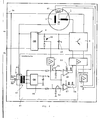
- the three-phase motor 1 is connected to network connections 2 of a single-phase AC network.
- the motor itself has two windings 3, 4, which are arranged spatially offset from one another, for example as stator windings around an armature of the motor (not shown).
- the main winding 3 is connected to one of its terminals 6 at a terminal 2a of the network 2, while the other terminal 7 of the main winding 3 is connected to a rectifier 8, such as a putting rectifier, the second primary terminal of which is connected to the mains contact 2b, during the rectifier 8, an inverter 9 is arranged downstream, a capacitor 10 being located between the two.
- the inverter 9 feeds the further motor winding 4 with a voltage, in particular shifted by 90 degrees, relative to the voltage at the mains connections 2 and thus at the first motor winding 3.
- the inverter 9 and thus the second winding 4 are therefore connected in series with the main winding 3.
- the inverter is represented by schematically represented switches 21 to 24 or switches 31, 32 and capacitors 33, 34, the schematically represented switches representing electronic switches.
- the auxiliary winding 4 is also shown.
- the connections 9a and 9b denote the connections of the inverter 9 (FIG. 1) to the rectifier 8.
- the switches 31, 32 are opened and closed alternately, as a result of which the capacitors 34, 33 are alternately charged via the auxiliary winding 4, while they each discharge after switching over, the other capacitor being charged in each case.
- the switching itself can be carried out in a manner known per se, for example in accordance with a pulse switching according to DE-OS 24 45 162.
- FIG. 4 shows a specific embodiment of a preferred synchronization circuit 41.
- the synchronization circuit 41 has a synchronization transformer 42 which is connected in parallel to the main winding 3 of the motor M via a switch 43.
- the switch 43 is designed as a changeover switch. The direction of rotation of the motor can be selected by switching over, in that the connection to the center tap of the primary winding of the transformer 42 is made to the right or bottom tap of the transformer.
- the transformer continues to supply the entire electronics with energy from the operating voltage Ub via the rectifier 44.
- a capacitor 1 is connected downstream of the transformer, which causes the phase shift of 90 degrees between the main and auxiliary windings 3, 4 of the motor M.
- the two connections of the secondary winding of the transformer lead to (plus) inputs of comparators 46, 47. Their (minus) input is connected to the output of the rectifier 8 via an amplifier V1.
- V1 the voltage on the main winding becomes the DC link voltage of the electronically controlled Compared winding.
- the outputs of the comparators 46, 47 act on the power transistors of the inverter 9 via an amplifier V2.
- the regulation is based on the principle of mutual influence: if the voltage in the intermediate circuit of the auxiliary winding, i.e. on capacitor C o (or 10) increases, the pulse width behind the comparators increases, which in turn leads to a formulation of the voltage on capacitor C o and thus increasing the tension on the main winding until a preselected tension distribution is reached. In the event that the voltage across the capacitor C o drops, the width of the output pulses of the comparators decreases, which in turn allows an optimal voltage to be leveled.
- the invention provides, in a manner known per se, that a temperature sensor 61 is provided in the motor, which acts via an amplifier 62 on the amplifier V 2 or the inverter 9 and can block it, as a result of which the motor is stopped in order to counter it To protect overheating.
- the motor according to the invention can also be provided with a DC brake.
Landscapes
- Engineering & Computer Science (AREA)
- Power Engineering (AREA)
- Control Of Ac Motors In General (AREA)
- Windings For Motors And Generators (AREA)
- Control Of Motors That Do Not Use Commutators (AREA)
- Liquid Developers In Electrophotography (AREA)
Priority Applications (1)
| Application Number | Priority Date | Filing Date | Title |
|---|---|---|---|
| AT89119033T ATE94700T1 (de) | 1988-10-28 | 1989-10-13 | Drehfeldmotor an einphasennetz. |
Applications Claiming Priority (2)
| Application Number | Priority Date | Filing Date | Title |
|---|---|---|---|
| DE8813560U DE8813560U1 (de) | 1988-10-28 | 1988-10-28 | Drehfeldmotor an Einphasennetz |
| DE8813560U | 1988-10-28 |
Publications (2)
| Publication Number | Publication Date |
|---|---|
| EP0366996A1 true EP0366996A1 (fr) | 1990-05-09 |
| EP0366996B1 EP0366996B1 (fr) | 1993-09-15 |
Family
ID=6829365
Family Applications (1)
| Application Number | Title | Priority Date | Filing Date |
|---|---|---|---|
| EP89119033A Expired - Lifetime EP0366996B1 (fr) | 1988-10-28 | 1989-10-13 | Moteur à induction sur réseau monophasé |
Country Status (3)
| Country | Link |
|---|---|
| EP (1) | EP0366996B1 (fr) |
| AT (1) | ATE94700T1 (fr) |
| DE (2) | DE8813560U1 (fr) |
Cited By (1)
| Publication number | Priority date | Publication date | Assignee | Title |
|---|---|---|---|---|
| CN103618493A (zh) * | 2013-12-04 | 2014-03-05 | 孙鲁西 | 单绕组单相交流电机控制模块 |
Citations (1)
| Publication number | Priority date | Publication date | Assignee | Title |
|---|---|---|---|---|
| DE2445162B2 (de) * | 1973-09-20 | 1980-10-30 | Unisearch Ltd., Kensington, Neusuedwales (Australien) | Einphasenasynchronmotor mit einem Käfigläufer |
-
1988
- 1988-10-28 DE DE8813560U patent/DE8813560U1/de not_active Expired - Lifetime
-
1989
- 1989-10-13 EP EP89119033A patent/EP0366996B1/fr not_active Expired - Lifetime
- 1989-10-13 AT AT89119033T patent/ATE94700T1/de not_active IP Right Cessation
- 1989-10-13 DE DE89119033T patent/DE58905615D1/de not_active Expired - Fee Related
Patent Citations (1)
| Publication number | Priority date | Publication date | Assignee | Title |
|---|---|---|---|---|
| DE2445162B2 (de) * | 1973-09-20 | 1980-10-30 | Unisearch Ltd., Kensington, Neusuedwales (Australien) | Einphasenasynchronmotor mit einem Käfigläufer |
Non-Patent Citations (1)
| Title |
|---|
| CONFERENCE RECORD OF THE 1988 IEEE INDUSTRY APPLICATIONS SOCIETY ANNUAL MEETING * |
Cited By (1)
| Publication number | Priority date | Publication date | Assignee | Title |
|---|---|---|---|---|
| CN103618493A (zh) * | 2013-12-04 | 2014-03-05 | 孙鲁西 | 单绕组单相交流电机控制模块 |
Also Published As
| Publication number | Publication date |
|---|---|
| DE58905615D1 (de) | 1993-10-21 |
| DE8813560U1 (de) | 1989-11-30 |
| EP0366996B1 (fr) | 1993-09-15 |
| ATE94700T1 (de) | 1993-10-15 |
Similar Documents
| Publication | Publication Date | Title |
|---|---|---|
| DE69313744T2 (de) | Wechselstrom-Antriebseinrichting mit veränderbarer Geschwindigkeit und Elektrofahrzeug hierfür | |
| DE102008014898A1 (de) | Verfahren zur Steuerung eines mehrphasigen Stromrichters mit verteilten Energiespeichern bei niedrigen Ausgangsfrequenzen | |
| DE3604755A1 (de) | Unterbrechungsfreie stromversorgung mit isolierter kopplungswicklung | |
| CH667167A5 (de) | Mehrphasige elektrische maschine mit variabler drehzahl. | |
| EP0589525B1 (fr) | Dispositif de commutation alimentant un moteur asynchrone à deux phases | |
| DE2225609A1 (de) | Mehrphasiger Wechselstrommotorantrieb mit einstellbarer Drehzahl | |
| DE2530112C3 (de) | Schaltungsanordnung zur Speisung eines Hysteresemotors | |
| EP3602762B1 (fr) | Onduleur | |
| DE3520631A1 (de) | Umrichter-vorrichtung | |
| DE3520632A1 (de) | Inverter | |
| DE69127808T2 (de) | Stromregler für induktive last | |
| DE3810870A1 (de) | Vorrichtung zum umformen von elektrischer energie | |
| DE69803353T2 (de) | Dreiphasiger, bürstenloser, Synchrongenerator mit verstärktem Läuferfeldsystem | |
| EP0045951B1 (fr) | Procédé pour mettre en marche un convertisseur ayant un circuit intermédiaire à courant continu alimentant un moteur électrique synchrone | |
| DE60002711T2 (de) | Bürstenloser Motor, Verfahren und Schaltung zu seiner Regelung | |
| DE3035305C2 (de) | Wechselrichterschaltung für einen Dreiphasen-Synchronmotor | |
| DE69803885T2 (de) | Steuerungsvorrichtung für elektrische motoren | |
| EP0474060B1 (fr) | Convertisseur de courant alternatif à quatre quadrants | |
| EP1584134A1 (fr) | Procede pour reduire les courants parasites en mode commun dans un systeme d'entrainement electrique, et systeme d'entrainement electrique correspondant | |
| EP0366996B1 (fr) | Moteur à induction sur réseau monophasé | |
| EP3531547A1 (fr) | Circuit de commande permettant de coupler une machine synchrone avec un réseau de tension et procédé de fonctionnement dudit circuit | |
| EP0212242A1 (fr) | Circuit de commande pour une charge alimentée par un courant alternatif, en série avec une batterie de condensateur | |
| DE2839712C3 (de) | Schaltung mit Zerhackerfunktion für einen bürstenlosen Gleichstrommotor | |
| DE69504547T2 (de) | Stromversorgungsvorrichtung für einen Wechselstrommotor | |
| DE10116156A1 (de) | Schaltungsanordnung zur Gewinnung einer Gleichspannung |
Legal Events
| Date | Code | Title | Description |
|---|---|---|---|
| PUAI | Public reference made under article 153(3) epc to a published international application that has entered the european phase |
Free format text: ORIGINAL CODE: 0009012 |
|
| AK | Designated contracting states |
Kind code of ref document: A1 Designated state(s): AT BE CH DE ES FR GB GR IT LI LU NL SE |
|
| 17P | Request for examination filed |
Effective date: 19901029 |
|
| 17Q | First examination report despatched |
Effective date: 19921120 |
|
| GRAA | (expected) grant |
Free format text: ORIGINAL CODE: 0009210 |
|
| AK | Designated contracting states |
Kind code of ref document: B1 Designated state(s): AT BE CH DE ES FR GB GR IT LI LU NL SE |
|
| PG25 | Lapsed in a contracting state [announced via postgrant information from national office to epo] |
Ref country code: IT Free format text: LAPSE BECAUSE OF FAILURE TO SUBMIT A TRANSLATION OF THE DESCRIPTION OR TO PAY THE FEE WITHIN THE PRE;WARNING: LAPSES OF ITALIAN PATENTS WITH EFFECTIVE DATE BEFORE 2007 MAY HAVE OCCURRED AT ANY TIME BEFORE 2007. THE CORRECT EFFECTIVE DATE MAY BE DIFFERENT FROM THE ONE RECORDED.SCRIBED TIME-LIMIT Effective date: 19930915 Ref country code: GB Effective date: 19930915 Ref country code: ES Free format text: THE PATENT HAS BEEN ANNULLED BY A DECISION OF A NATIONAL AUTHORITY Effective date: 19930915 Ref country code: FR Effective date: 19930915 Ref country code: BE Effective date: 19930915 Ref country code: SE Effective date: 19930915 Ref country code: GR Free format text: LAPSE BECAUSE OF FAILURE TO SUBMIT A TRANSLATION OF THE DESCRIPTION OR TO PAY THE FEE WITHIN THE PRESCRIBED TIME-LIMIT Effective date: 19930915 Ref country code: NL Effective date: 19930915 |
|
| REF | Corresponds to: |
Ref document number: 94700 Country of ref document: AT Date of ref document: 19931015 Kind code of ref document: T |
|
| PG25 | Lapsed in a contracting state [announced via postgrant information from national office to epo] |
Ref country code: AT Effective date: 19931013 |
|
| REF | Corresponds to: |
Ref document number: 58905615 Country of ref document: DE Date of ref document: 19931021 |
|
| PG25 | Lapsed in a contracting state [announced via postgrant information from national office to epo] |
Ref country code: LU Free format text: LAPSE BECAUSE OF NON-PAYMENT OF DUE FEES Effective date: 19931031 Ref country code: CH Effective date: 19931031 Ref country code: LI Effective date: 19931031 |
|
| EN | Fr: translation not filed | ||
| NLV1 | Nl: lapsed or annulled due to failure to fulfill the requirements of art. 29p and 29m of the patents act | ||
| GBV | Gb: ep patent (uk) treated as always having been void in accordance with gb section 77(7)/1977 [no translation filed] |
Effective date: 19930915 |
|
| REG | Reference to a national code |
Ref country code: CH Ref legal event code: PL |
|
| PLBE | No opposition filed within time limit |
Free format text: ORIGINAL CODE: 0009261 |
|
| STAA | Information on the status of an ep patent application or granted ep patent |
Free format text: STATUS: NO OPPOSITION FILED WITHIN TIME LIMIT |
|
| 26N | No opposition filed | ||
| PGFP | Annual fee paid to national office [announced via postgrant information from national office to epo] |
Ref country code: DE Payment date: 19961029 Year of fee payment: 8 |
|
| PG25 | Lapsed in a contracting state [announced via postgrant information from national office to epo] |
Ref country code: DE Free format text: LAPSE BECAUSE OF NON-PAYMENT OF DUE FEES Effective date: 19980701 |