EP0366902A2 - Method of and installation for compacting foundry mold material - Google Patents
Method of and installation for compacting foundry mold material Download PDFInfo
- Publication number
- EP0366902A2 EP0366902A2 EP89116348A EP89116348A EP0366902A2 EP 0366902 A2 EP0366902 A2 EP 0366902A2 EP 89116348 A EP89116348 A EP 89116348A EP 89116348 A EP89116348 A EP 89116348A EP 0366902 A2 EP0366902 A2 EP 0366902A2
- Authority
- EP
- European Patent Office
- Prior art keywords
- pressure
- valve
- molding
- throttle element
- molding space
- Prior art date
- Legal status (The legal status is an assumption and is not a legal conclusion. Google has not performed a legal analysis and makes no representation as to the accuracy of the status listed.)
- Granted
Links
Images

Classifications
-
- B—PERFORMING OPERATIONS; TRANSPORTING
- B22—CASTING; POWDER METALLURGY
- B22C—FOUNDRY MOULDING
- B22C15/00—Moulding machines characterised by the compacting mechanism; Accessories therefor
-
- B—PERFORMING OPERATIONS; TRANSPORTING
- B22—CASTING; POWDER METALLURGY
- B22C—FOUNDRY MOULDING
- B22C9/00—Moulds or cores; Moulding processes
- B22C9/12—Treating moulds or cores, e.g. drying, hardening
- B22C9/123—Gas-hardening
Definitions
- the invention relates to a method and a device for compressing foundry molding material which has been heaped up in a molding space above a model by means of a compressed gas, which suddenly relaxes into the molding space with a relatively lower, then with a high pressure gradient and compresses the molding material as a result of the pressure surge .
- the object of the present invention is to provide a method and a device for the compression of foundry molding material which is distinguished on the one hand by good compression values in critical model areas and on the other by a short cycle time.
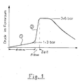
- the first section of the pressure curve expediently runs from atmospheric pressure to an intermediate value of 1 to 3 bar gauge pressure, the subsequent section from this intermediate value to the final pressure, which, as usual, is approximately 4 to 6 bar.
- Different control mechanisms can be used so that a pressure increase with the desired different pressure gradients can be realized within one and the same pressure surge. It is particularly expedient to generate the pressure surge to generate the first, flatter pressure increase in such a way that the relaxation of the pressure surge from the pressure chamber into the molding space is artificially throttled during this period. If the second section should then begin with the higher pressure gradient, this throttling effect only needs to be eliminated.
- This procedure has the advantage that it is possible to work with the valve constructions that have already been tried and tested in practice and that one only has to delay the opening movement of this valve somewhat at the beginning. This then automatically results in an initially flat pressure rise, which then, when the valve opens further and without delay, changes into the steeper pressure increase already practiced.
- a particularly expedient development of the invention consists in generating the pressure surge with its two differently steep sections only over the area of the molding material which is essentially above the model or models, whereas the molding material in the edge area with the usual continuously steep pressure surge, without throttling.
- a device for carrying out the method In the simplest case, one starts from the conventional molding machine with a pressure pulse, in which the valve between the pressure chamber and the molding chamber is actuated by a hydraulic and / or pneumatic pressure medium. In order to bring about the intended delay at the beginning of the opening movement of this valve, an adjustable throttle valve only needs to be installed in a pressure medium line for controlling this valve.
- the flow cross section of the throttle element should be adjustable from about 0% to about 50%, in particular up to about 30% of the free cross section.
- the opening time of the throttle element is adjustable to match the model contour.
- the throttle element can be opened at least partially during the opening movement of the pressure chamber valve.
- the throttle element be formed by perforated plates which are displaceable relative to one another. In one position the perforated plates cover the holes of the neighboring plate, in the other position the perforated plates are aligned.
- the throttle element does not have to extend over the entire cross section of the molding space, but is recommended if it is only in the area above of the model is arranged. In contrast, the rest of the area can remain free. Usually this is the edge area - however, the situation is reversed when shaping bathtubs.
- the throttle element have bulkheads which plunge down into the molding material. These bulkheads extend through the filling frame and, if necessary, also a piece into the molding box.
- Another device for carrying out the method according to the invention is characterized in that two valves are provided between the pressure chamber or the pressure chambers on the one hand and the molding space on the other hand, and that one valve is connected to the inner region of the molding space, which is essentially above the model is located, whereas the other valve is connected to the model-free edge area of the molding space.
- the pressure in the mold space is first increased with an unusually low pressure gradient of 30 to 100 bar / sec until a pressure of approximately 1 to 3 bar is reached.
- This first pressure section 1 then merges seamlessly into a substantially steeper pressure section 2 which has the pressure gradient of approximately 100 to 600 bar / sec that is customary in pulse compression.
- the pressure equalization between the pressure chamber and the molding space is as before at around 3 to 6 bar.
- the pressure reduction then begins, in which the compressed gas escapes through gaps in the molding space and / or through deliberately provided openings, and is optionally suctioned off. The latter comes into consideration if a reaction gas is used as the compressed gas, which brings about a chemical hardening of the molding material.
- the section 1 upstream of the conventional pressure increase 2 causes intensive fluidization of the filled molding material.
- the resulting improved flowability benefits the pressure section 2, which is decisive for the compression, because this pressure section connects directly before the air from the pressure section 1 leaves the molding space.
- the ventilation by the first pressure surge has already largely decayed when the second pressure surge begins.
- the pressure curve according to the invention is therefore particularly suitable for molds with deep bales.
- a pressure vessel 5 - in the exemplary embodiment for receiving compressed air - which is connected via a connection 6 from a pressure accumulator or from the company Compressed air network is fed.
- the pressure vessel has a plate which is provided with a plurality of openings 8 in a rust-like manner in the area above the molding space.
- a frame 9 is flanged to the top of the base 7, to which an exhaust air line with a valve 10 is in turn connected.
- the pressure container 5 with the frame 9 on the one hand and the model plate 1 with model 2, molding box 3 and filling frame 4 on the other hand can be moved relative to one another in order to be able to fill the molding space with molding material to just below the bottom 7. Before the compression, the two assemblies are brought together and pressed tightly at their interface.
- a sealing coating 13 is attached to the underside of the valve plate within the area of the openings 12.
- valve plate 11 is seated on a guide rod 14, which at the same time forms the piston rod of a piston 15 of a pressure medium cylinder 16. This and the control system are described below with reference to FIG. 3.
- the pressure medium cylinder 16 is arranged in a hydraulic circuit, the pressure source of which is designated 17. This is, for example, a hydraulic pump that is fed from a tank 18. From the pressure source 17, the pressure medium reaches the pressure chamber 22 of the pressure medium cylinder 16 via a control slide 19, a check valve 20 and the feed line 21.
- the pressure medium cylinder 16 has a gas pressure chamber 24 which is connected to one Gas pressure accumulator 25 is connected.
- This gas pressure accumulator 25 is divided by a movable piston 26 into a gas pressure chamber 27 and a hydraulic pressure chamber 28.
- the hydraulic pressure chamber 28 is connected via a control slide 29 to a high-pressure source 30, which is fed from the supply tank 18.
- the piston 15 of the pressure medium cylinder 16 is extended on the hydraulic side with a piston rod 31 passing through the pressure chamber 22.
- This upper piston rod 31 carries a cylindrical shoulder 32 and a conically tapered shoulder 33 directly on the shoulder of the piston 15, which forms a throttle with the cylindrical constriction 34 during an upward stroke movement of the piston 15.
- the hydraulic feed line 21 also leads to a controllable check valve 23, the control line of which can be connected to the pressure source 17 via the control slide 19.
- the pressure medium chamber is connected via a branch from the line 21 to an outlet tank 37 and a vent line 38 in a pressure-relieved manner.
- the drain line 39 of the drain tank 37 opens into the hydraulic tank 18.
- the aforementioned branch goes from the feed line 21 to an adjustable throttle 35 and a downstream control slide 36, both of which are connected in parallel to the check valve 23 are and which allow a slow drain of the pressure medium from the pressure chamber 22.
- the check valve 23 After, for example, 50 milliseconds, the check valve 23 also jumps into the open position, so that the outflow from the pressure chamber 22 is released unhindered. The valve 11 then opens abruptly in the previously usual manner up to the maximum opening position and thus generates section 2 of the pressure curve.
- valve 11 The closing of the valve 11 and the other control functions are described in detail in DE-OS 35 18 980, so that reference can be made to avoid repetition.
- a proportional valve is particularly useful. It replaces the check valve 23, the throttle 35 and the control slide 36.
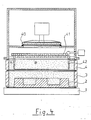
- FIG. 4 shows another implementation possibility for bringing about the pressure curve according to the invention. Only a schematic section of the molding machine is shown, consisting of model plate 1, model 2, molding box 3, filling frame 4 and a mold space opposite valve 40 closing pressure chamber 5.
- the valve 40 is only shown schematically. This can be a construction according to FIG. 2 or any other valve construction. It only has to be ensured that this valve opens quickly enough to bring about a pressure rise rate of 100 to 600 bar / sec in the molding space above the molding material. In contrast, the valve 40 does not need to perform a delayed opening movement as described in FIGS. 2 and 3. The delayed pressure rise at the beginning of the pressure curve is generated here in a different way and is limited to that area of the molding material which is located approximately above the model.
- a throttle element 41 is arranged in the space between the valve 40 and the top of the filled molding material.
- This throttle element consists of two adjacent, horizontally displaceable, rust-like perforated plates, the holes of which are arranged so that they are almost or completely closed in one position of the throttle element, but are open in the other position.
- Such grate plate valves and their actuation are known per se in molding machines, so that there is no need to go into them in detail.
- baffles 42 projecting downwards. These baffles are immersed in the molded material and extend close to or into the molding box. They are positioned so that they are roughly aligned with the outer contour of the models.
- this throttle element is as follows: If the valve 40 is opened, the throttle element 41 is initially almost closed, so that the pressure pulse can only propagate unhindered into the edge region A of the molding space.
- the inner area B which is located below the throttle element 41, however, is only subjected to an attenuated pressure pulse, the pressure gradient of which corresponds to section 1 of the pressure curve in FIG. 1.
- the throttle element 41 goes into its maximum open position and the pressure correspondingly increases with the pressure gradient of section 2 of FIG. 1.
- the design according to FIG. 4 thus allows the pressure curve according to the invention to be used only in that area of the molding material which is essentially above the model, whereas the model-free edge area is subjected to a continuously steep characteristic curve by the conventional pressure pulse.
- the design according to FIG. 5 permits an even more individual pressurization of different areas of the molding space.
- the edge area A and inner area B are each connected to their own valves 50 and 51, respectively. Both valves can be opened separately by an individual delay circuit. They are either connected to a common or separate pressure chambers.
- the separation between the areas of the molding space is made by walls 52 which enclose the outlet of the valve 51, then expand above the molding material to the cross section above the model and merge into the vertical guide plates 42.
Abstract
Description
Die Erfindung betrifft ein Verfahren und eine Vorrichtung zum Verdichten von in einem Formraum über einem Modell aufgeschüttetem Gießerei-Formstoff mittels eines Druckgases, das sich schlagartig mit zunächst einem relativ niedrigeren, danach mit einem hohen Druckgradient in den Formraum entspannt und infolge des Druckstoßes den Formstoff verdichtet.The invention relates to a method and a device for compressing foundry molding material which has been heaped up in a molding space above a model by means of a compressed gas, which suddenly relaxes into the molding space with a relatively lower, then with a high pressure gradient and compresses the molding material as a result of the pressure surge .
Dieses sogenannte Luftimpulsverfahren hat sich grundsätzlich bei der Verdichtung von Gießerei-Formstoff bewährt. Es geht jetzt im wesentlichen noch darum, homogen verdichtete Formen mit hoher Härte auch bei formtechnisch schwierigen Modellen mit abrupten Höhendifferenzen der Modellkontur oder mit geringem Randabstand sicherzustellen.This so-called air pulse process has generally proven itself in the compression of foundry molding material. It is now essentially a question of homogeneously compacted forms with high Ensure hardness even with difficult models with abrupt differences in height of the model contour or with a small edge distance.
Zu diesem Zweck ist es durch die DE-OS 33 17 196 bekannt geworden, über der Formstoff-Oberfläche eine gasdurchlässige Schicht anzuordnen, deren Gasdurchlässigkeit im Bereich oberhalb des Modelles geringer ist als im modellfreien Randbereich. Dadurch ergibt sich bereits eine deutlich verbesserte Anpassung der Formhärte an die Gegebenheiten des Modells.For this purpose, it has become known from DE-OS 33 17 196 to arrange a gas-permeable layer above the molding material surface, the gas permeability of which is lower in the region above the model than in the model-free edge region. This results in a significantly improved adaptation of the mold hardness to the conditions of the model.
Sodann ist es durch die DE-OS 37 40 775 bekannt, die Verdichtung nicht mit einem, sondern mit zwei aufeinanderfolgenden Druckstößen herbeizuführen, wobei der Druckgradient des ersten Druckstoßes kleiner als der des zweiten Druckstoßes ist. Dieser zweifache Druckstoß führt jedoch zu einer Verlängerung der Taktzeit der Formmaschine.Then it is known from DE-OS 37 40 775 to bring about the compression not with one but with two successive pressure surges, the pressure gradient of the first pressure surge being smaller than that of the second pressure surge. However, this double pressure surge leads to an increase in the cycle time of the molding machine.
Hiervon ausgehend liegt die Aufgabe der vorliegenden Erfindung darin, ein Verfahren und eine Vorrichtung zur Verdichtung von Gießerei-Formstoff anzugeben, das sich einerseits durch gute Verdichtungswerte auch in kritischen Modellbereichen, andererseits durch kurze Taktzeit auszeichnet.Proceeding from this, the object of the present invention is to provide a method and a device for the compression of foundry molding material which is distinguished on the one hand by good compression values in critical model areas and on the other by a short cycle time.
Diese Aufgabe wird erfindungsgemäß hinsichtlich des Verfahrens dadurch gelöst, daß die unterschiedlich hohen Durckgradienten innerhalb eines einzigen Druckstoßes erzeugt werden, derart, daß sich der mit dem hohen Druckgradienten ansteigende Bereich der Druckkurve direkt an den ersten, flacheren Bereich der Druckkurve anschließt.This object is achieved with regard to the method in that the differently high pressure gradients are generated within a single pressure surge in such a way that the region of the pressure curve which rises with the high pressure gradient directly adjoins the first, flatter region of the pressure curve.
Untersuchungen der Anmelderin haben erstaunlicherweise ergeben, daß ein derart gesteuerter Druckimpuls wesentlich bessere Verdichtungswerte ergibt als ein herkömmlicher Druckimpuls. Ursächlich hierfür dürfte folgende Erklärung sein: Durch den ersten, relativ flachen Bereich des Druckanstieges wird der Formstoff im wesentlichen nur fluidisiert, also seine Fließfähigkeit verbessert, ohne daß es zu einer nennenswerten Verdichtung kommt. Der hierauf folgende weitere Druckanstieg, der mit dem für die Verdichtung üblichen steilen Druckgradient erfolgt, profitiert von den verbesserten Fließeigenschaften des Formstoffes, weil er sich innerhalb des gleichen Druckstoßes lückenlos an den zuvor erreichten Druck anschließt. Die Verdichtungsfähigkeit gerade in engen Bereichen zwischen einzelnen Modellen oder zwischen Modell und Formkasten wird dadurch bedeutend verbessert. Die Taktzeit des erfindungsgemäßen Verfahrens bleibt nahezu die gleiche, weil sich alle Vorgänge bei ein und demselben Druckimpuls abspielen.Investigations by the applicant have surprisingly shown that a pressure pulse controlled in this way gives significantly better compression values than a conventional pressure pulse. The reason for this is probably the following explanation: The first, relatively flat area of the pressure increase essentially only fluidizes the molding material, that is, improves its flowability without causing any noteworthy compression. The subsequent further pressure increase, which takes place with the steep pressure gradient customary for compression, benefits from the improved flow properties of the molding material, because it seamlessly follows the pressure previously reached within the same pressure surge. This significantly improves the compressibility, especially in narrow areas between individual models or between model and molding box. The cycle time of the method according to the invention remains almost the same, because all processes take place with one and the same pressure pulse.
Zweckmäßigerweise läuft der erste Abschnitt der Druckkurve von Atmosphärendruck bis zu einem Zwischenwert von 1 bis 3 bar Überdruck, der anschließende Abschnitt von diesem Zwischenwert bis zum Enddruck, der wie üblich bei etwa 4 bis 6 bar liegt.The first section of the pressure curve expediently runs from atmospheric pressure to an intermediate value of 1 to 3 bar gauge pressure, the subsequent section from this intermediate value to the final pressure, which, as usual, is approximately 4 to 6 bar.
Damit sich ein Druckanstieg mit den gewünschten unterschiedlichen Druckgradienten innerhalb ein und desselben Druckstoßes realisieren läßt, können unterschiedliche Steuerungsmechanismen verwendet werden. Besonders günstig ist es, den Druckstoß zu Erzeugung des ersten, flacheren Druckanstieges in der Weise zu erzeugen, daß in dieser Zeitspanne die Entspannung des Druckstoßes aus der Druckkammer in den Formraum künstlich gedrosselt wird. Wenn dann der zweite Abschnitt mit dem höheren Druckgradient beginnen soll, braucht diese Drosselwirkung lediglich aufgehoben zu werden. Bei diesem Vorgehen ergibt sich der Vorteil, daß mit den bereits in der Praxis bewährten Ventilkonstruktionen gearbeitet werden kann und daß man lediglich die Öffnungsbewegung dieses Ventiles zu Beginn etwas verzögern muß. Es ergibt sich dann automatisch ein zunächst flacher Druckanstieg, der dann, wenn das Ventil sich weiter und ohne Verzögerung öffnet, in den schon bisher praktizierten steileren Druckanstieg übergeht.Different control mechanisms can be used so that a pressure increase with the desired different pressure gradients can be realized within one and the same pressure surge. It is particularly expedient to generate the pressure surge to generate the first, flatter pressure increase in such a way that the relaxation of the pressure surge from the pressure chamber into the molding space is artificially throttled during this period. If the second section should then begin with the higher pressure gradient, this throttling effect only needs to be eliminated. This procedure has the advantage that it is possible to work with the valve constructions that have already been tried and tested in practice and that one only has to delay the opening movement of this valve somewhat at the beginning. This then automatically results in an initially flat pressure rise, which then, when the valve opens further and without delay, changes into the steeper pressure increase already practiced.
Eine besonders zweckmäßige Weiterbildung der Erfindung besteht darin, den Druckstoß mit seinem beiden unterschiedlich steilen Abschnitten nur über dem Bereich des Formstoffes zu erzeugen, der sich im wesentlichen oberhalb des Modelles oder der Modelle befindet, wogegen der Formstoff im Randbereich mit dem üblichen durchgehend steilen Druckstoß, also ohne Drosselung, beaufschlagt wird.A particularly expedient development of the invention consists in generating the pressure surge with its two differently steep sections only over the area of the molding material which is essentially above the model or models, whereas the molding material in the edge area with the usual continuously steep pressure surge, without throttling.
Durch diese Aufteilung des Formraumes wird die Sandbewegung über dem Modell verzögert und dadurch kann der Sand etwa zum gleichen Zeitpunkt seine Endverdichtung sowohl am Modell wie auch an modellfreien Partien erreichen. Man erhält somit eine ideal homogene Verdichtung.This division of the mold space delays the sand movement over the model, which means that the sand can achieve its final compaction at the same time, both on the model and on model-free sections. An ideally homogeneous compaction is thus obtained.
Als Vorrichtung zur Durchführung des Verfahrens bieten sich verschiedene Realisierungsmöglichkeiten. Im einfachsten Fall geht man von der herkömmlichen Formmaschine mit Druckimpuls aus, bei der die Betätigung des Ventiles zwischen Druckkammer und Formraum durch ein hydraulisches und/oder pneumatisches Druckmittel erfolgt. Um die beabsichtigte Verzögerung zu Beginn der Öffnungsbewegung dieses Ventiles herbeizuführen braucht lediglich in eine Druckmittelleitung zur Steuerung dieses Ventiles ein verstellbares Drosselventil eingebaut zu werden.Various implementation options are available as a device for carrying out the method. In the simplest case, one starts from the conventional molding machine with a pressure pulse, in which the valve between the pressure chamber and the molding chamber is actuated by a hydraulic and / or pneumatic pressure medium. In order to bring about the intended delay at the beginning of the opening movement of this valve, an adjustable throttle valve only needs to be installed in a pressure medium line for controlling this valve.
Bei solchen Formmaschinen, die etwa gemäß der DE-OS 33 17 196 oberhalb des unverdichteten Form stoffes eine gasdurchlässige Schicht mit reduzierter Gasdurchlässigkeit im Bereich hoher Modellkonturen aufweisen, ist es am günstigsten, diese Schicht als mechanisches Drosselelement auszubilden, dessen Gasdurchlässigkeit verstellbar ist. Dadurch läßt sich ebenfalls zu Beginn des Druckimpulses eine verringerte Gasdurchlässigkeit und somit die gewünschte Änderung der Druckanstiegsgeschwindigkeit herbeiführen.In such molding machines, which according to DE-OS 33 17 196 above the undensified form have a gas-permeable layer with reduced gas permeability in the area of high model contours, it is most advantageous to design this layer as a mechanical throttle element whose gas permeability is adjustable. This also allows a reduced gas permeability and thus the desired change in the rate of pressure rise to be brought about at the beginning of the pressure pulse.
Dabei sollte der Durchströmquerschnitt des Drosselelementes von etwa 0 % bis etwa 50 %, insbesondere bis etwa 30 % des freien Querschnittes verstellbar sein. Die Öffnungszeit des Drosselelementes ist zur Anpassung an die Modellkontur verstellbar. Öffnung des Drosselelementes kann zumindest teilweise während der Öffnungsbewegung des Druckkammer-Ventiles erfolgen.The flow cross section of the throttle element should be adjustable from about 0% to about 50%, in particular up to about 30% of the free cross section. The opening time of the throttle element is adjustable to match the model contour. The throttle element can be opened at least partially during the opening movement of the pressure chamber valve.
In konstruktiver Hinsicht empfiehlt es sich, daß das Drosselelement durch relativ zueinander verschiebbare Lochplatten gebildet ist. In der einen Stellung decken die Lochplatten jeweils die Löcher der Nachbarplatte zu, in der anderen Stellung fluchten die Lochplatten.From a design point of view, it is recommended that the throttle element be formed by perforated plates which are displaceable relative to one another. In one position the perforated plates cover the holes of the neighboring plate, in the other position the perforated plates are aligned.
Wie schon an anderer Stelle erwähnt, braucht sich das Drosselelement nicht über den gesamten Querschnitt des Formraumes zu erstrecken, sondern es empfiehlt sich, wenn es nur im Bereich oberhalb des Modells angeordnet ist. Hingegen kann der übrige Bereich frei bleiben. Normalerweise ist dies der Randbereich - beim Formen von Badewannen jedoch liegen die Verhältnisse bekanntlich umgekehrt.As already mentioned elsewhere, the throttle element does not have to extend over the entire cross section of the molding space, but is recommended if it is only in the area above of the model is arranged. In contrast, the rest of the area can remain free. Usually this is the edge area - however, the situation is reversed when shaping bathtubs.
Damit die Zonen unterschiedlicher Gasdurchlässigkeit auch in vertikaler Richtung gegeneinander abgegrenzt sind, empfiehlt es sich, daß das Drosselelement nach unten in den Formstoff eintauchende Schottwände aufweist. Diese Schottwände erstrecken sich durch den Füllrahmen hindurch und gegebenenfalls auch ein Stück in den Formkasten hinein.So that the zones of different gas permeability are also delimited from one another in the vertical direction, it is recommended that the throttle element have bulkheads which plunge down into the molding material. These bulkheads extend through the filling frame and, if necessary, also a piece into the molding box.
Eine weitere Vorrichtung zur Durchführung des erfindungsgemäßen Verfahrens zeichnet sich dadurch aus, daß zwei Ventile zwischen der Druckkammer beziehungsweise den Druckkammern einerseits und dem Formraum andererseits vorgesehen sind und daß das eine Ventil an den inneren Bereich des Formraumes angeschlossen ist, der sich im wesentlichen über dem Modell befindet, wogegen das andere Ventil an den modellfreien Randbereich des Formraumes angeschlossen ist. Dadurch ist eine weitgehend individuelle Druckbeaufschlagung einzelner Bereiche des Formraumes in Abhängigkeit von den dort herrschenden Modell-Gegebenheiten möglich. Durch Schottwände, die in den Sand eintauchen ist eine gegenseitige Beeinflußung der Druckverhältnisse weitgehend auf das Ende des Druckimpulses beschränkt.Another device for carrying out the method according to the invention is characterized in that two valves are provided between the pressure chamber or the pressure chambers on the one hand and the molding space on the other hand, and that one valve is connected to the inner region of the molding space, which is essentially above the model is located, whereas the other valve is connected to the model-free edge area of the molding space. This enables largely individual pressurization of individual areas of the molding space, depending on the model conditions prevailing there. Due to bulkheads that dip into the sand, mutual influence of the pressure conditions is largely limited to the end of the pressure pulse.
Bei großen Formraumquerschnitten liegt es im Rahmen der Erfindung, nicht nur mit zwei, sondern mit mehr Ventilen zu arbeiten und dadurch insbesondere den inneren Bereich des Formraumes in mehrere Räume zu unterteilen.In the case of large cross sections of the molding space, it is within the scope of the invention to work not only with two, but with more valves, and in this way in particular to divide the inner region of the molding space into several rooms.
Weitere Merkmale und Vorteile der Erfindung ergeben sich aus der nachfolgenden Beschreibung von Ausführungsbeispielen anhand der Zeichnung; dabei zeigt
Figur 1 den erfindungsgemäßen Druckverlauf über der Zeit;Figur 2 eine Formmaschine im Vertikalschnitt;Figur 3 daß dazugehörige Steuerschema;- Figur 4 einen Ausschnitt einer Formmaschine mit einem anderen Ventil und
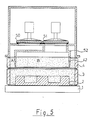
Figur 5 einen ähnlichen Ausschnitt mit zwei Ventilen.
- Figure 1 shows the pressure curve according to the invention over time;
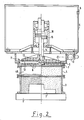
- Figure 2 shows a molding machine in vertical section;
- Figure 3 that associated control scheme;
- Figure 4 shows a section of a molding machine with another valve and
- Figure 5 shows a similar section with two valves.
In Figur 1 ist aufgetragen auf der Ordinate der Druck im Formraum über der Sandoberfläche und auf der Abszisse die Zeit.In Figure 1, the ordinate shows the pressure in the mold space above the sand surface and the time on the abscissa.
Erfindungsgemäß wird der Druck im Formraum zunächst mit einem ungewöhnlich niedrigen Druckgradient von 30 bis 100 bar/sec erhöht, bis ein Druck von etwa 1 bis 3 bar erreicht ist. Dieser erste Druckabschnitt 1 geht sodann lückenlos über in einen wesentlich steileren Druckabschnitt 2, der den bei der Impulsverdichtung üblichen Druckgradient von etwa 100 bis 600 bar/sec aufweist. Der Druckausgleich zwischen der Druckkammer und dem Formraum stellt sich wie bisher bei etwa 3 bis 6 bar ein. Danach beginnt der Druckabbau, in dem das Druckgas durch Spalte im Formraum und/oder durch bewußt angebrachte Öffnungen entweicht, gegebenenfalls abgesaugt wird. Letzteres kommt in Betracht, wenn als Druckgas ein Reaktionsgas verwendet wird, das eine chemische Aushärtung des Formstoffes herbeiführt.According to the invention, the pressure in the mold space is first increased with an unusually low pressure gradient of 30 to 100 bar / sec until a pressure of approximately 1 to 3 bar is reached. This
Der dem herkömmlichen Druckanstieg 2 vorgeschaltete Abschnitt 1 bewirkt eine intensive Fluidisierung des eingefüllten Formstoffes. Die dadurch verbesserte Fließfähigkeit kommt in vollem Umfange dem für die Verdichtung entscheidenden Druckabschnitt 2 zugute, weil sich dieser Druckabschnitt direkt anschließt bevor die Luft aus dem Druckabschnitt 1 den Formraum verläßt. Im Gegensatz dazu ist bei dem bekannten Verfahren mittels zweier aufeinanderfolgender Druckstöße die Belüftung durch den ersten Druckstoß bereits weitgehend abgeklungen, wenn der zweite Druckstoß beginnt.The
Der erfindungsgemäße Druckverlauf ist daher besonders für Formen mit tiefen Ballen geeignet.The pressure curve according to the invention is therefore particularly suitable for molds with deep bales.
Um zu demonstrieren, daß sich der erfindungsgemäße Druckverlauf auch nachträglich in bereits bestehenden Formanlagen realisieren läßt, wird zur weiteren Beschreibung auf die bekannte Ventilsteuerung gemäß P 35 18 980.0 zurückgegriffen. Diese Anlage ist in Figur 2 dargestellt, wobei nur die zum Verständnis der Erfindung notwendigen Teile der Verdichtungsvorrichtung wiedergegeben sind.In order to demonstrate that the pressure curve according to the invention can also be subsequently implemented in already existing molding plants, the known valve control according to
Auf einer Modellplatte 1 mit einem Modell 2 sitzt ein Formkasten 3 und auf diesem ein Füllrahmen 4. Oberhalb des so gebildeten Formraumes ist ein Druckbehälter 5 - im Ausführungsbeispiel zur Aufnahme von Druckluft - angeordnet, der über einen Anschluß 6 aus einem Druckspeicher oder aus dem betrieblichen Druckluftnetz gespeist wird.On a
Der Druckbehälter weist eine Platte auf, die im Bereich oberhalb des Formraumes rostartig mit einer Vielzahl von Öffnungen 8 versehen ist. An der Oberseite des Bodens 7 ist ein Rahmen 9 angeflanscht, an den wiederum eine Abluftleitung mit einem Ventil 10 angeschlossen ist.The pressure vessel has a plate which is provided with a plurality of
Der Durckbehälter 5 mit dem Rahmen 9 einerseits und die Modellplatte 1 mit Modell 2, Formkasten 3 und Füllrahmen 4 andererseits sind gegeneinander beweglich, um den Formraum bis unmittelbar unterhalb des Bodens 7 mit Formstoff füllen zu können. Vor dem Verdichten werden die beiden Baugruppen zusammengebracht und an ihrer Trennfläche dicht zusammengepreßt.The
Mit dem Boden 7 beziehungsweise dessen die Öffnungen 8 aufweisenden Bereich wirkt ein Verschlußorgan in Form einer starren Ventilplatte 11 zusammen, die gleichfalls eine Vielzahl von Öffnungen 12 besitzt. Außerdem ist auf der Unterseite der Ventilplatte innerhalb des Bereiches der Öffnungen 12 ein Dichtungsbelag 13 angebracht. Die Öffnungen 8 im Boden 7 und die Öffnungen 12 in der Ventilplatte 11 sind so gegeneinander versetzt, daß sie sich in der Schließlage gegenseitig versperren.A closure member in the form of a
Die Ventilplatte 11 sitzt an einer Führungsstange 14, die zugleich die Kolbenstange eines Kolbens 15 eines Druckmittelzylinders 16 bildet. Dieser und die Steuerung werden nachfolgend anhand der Figur 3 beschrieben.The
Der Druckmittelzylinder 16 ist in einem Hydraulik-Kreislauf angeordnet, dessen Druckquelle mit 17 bezeichnet ist. Dabei handelt es sich beispielsweise um eine Hydraulikpumpe, die aus einem Tank 18 gespeist wird. Von der Druckquelle 17 gelangt das Druckmittel über einen Steuerschieber 19, ein Rückschlagventil 20 und die Zuleitung 21 in den Druckraum 22 des Druckmittelzylinders 16.The
Unterhalb seines Kolbens 15 weist der Druckmittelzylinder 16 einen Gasdruckraum 24 auf, der an einen Gasdruckspeicher 25 angeschlossen ist. Dieser Gasdruckspeicher 25 ist durch einen beweglichen Kolben 26 in einen Gasdruckraum 27 und einen Hydraulikdruckraum 28 unterteilt. Der Hydraulikdruckraum 28 ist über einen Steuerschieber 29 mit einer Hochdruckquelle 30 verbunden, die aus dem Versorgungstank 18 gespeist wird.Below its
Der Kolben 15 des Druckmittelzylinders 16 ist auf der Hydraulikseite mit einer den Druckraum 22 durchgreifenden Kolbenstange 31 verlängert. Diese obere Kolbenstange 31 trägt unmittelbar am Ansatz des Kolbens 15 einen zylindrischen Ansatz 32 und einen konisch verjüngten Ansatz 33, der bei einer Aufwärtshubbewegung des Kolbens 15 mit der zylindrischen Verengung 34 eine Drossel bildet.The
Die hydraulische Zuleitung 21 führt noch zu einem steuerbaren Rückschlagventil 23, dessen Steuerleitung über den Steuerschieber 19 mit der Druckquelle 17 verbindbar ist. Der Druckmittelraum ist in entsperrtem Schaltzustand des Rückschlagventils 23 über eine Abzweigung von der Leitung 21 mit einem Ablauftank 37 und einer Entlüfungsleitung 38 druckentlastet verbunden. Die Abflußleitung 39 des Ablauftanks 37 mündet in den Hydrauliktank 18.The
Außerdem geht die vorgenannte Abzweigung von der Zuleitung 21 zu einer einstellbaren Drossel 35 und einem nachgeordneten Steuerschieber 36, die beide parallel zu dem Rückschlagventil 23 geschaltet sind und die einen langsamen Ablauf des Druckmittels aus dem Druckraum 22 zulassen.In addition, the aforementioned branch goes from the
Dadurch kann mit Hilfe der Drossel 35, die anfänglich nur einen kleinen Rücklaufquerschnitt freigibt und in Verbindung mit dem geöffneten Steuerschieber 36 die Hubbewegung des Kolbens 15 und damit der Ventilplatte 11 gebremst und der flache Druckabschnitt 1 im Druckdiagramm von Figur 1 realisiert werden.As a result, with the help of the
Nach beispielsweise 50 Millisekunden springt zusätzlich das Rückschlagventil 23 in die Durchlaßstellung, so daß der Abfluß aus dem Druckraum 22 ungehindert freigegeben wird. Das Ventil 11 öffnet sich dann schlagartig in der schon bisher üblichen Weise bis zur maximalen Öffnungsstellung und erzeugt damit den Abschnitt 2 der Druckkurve.After, for example, 50 milliseconds, the
Das Schließen des Ventils 11 und die übrigen Steuerfunktionen sind ausführlich in der DE-OS 35 18 980 beschrieben, so daß zur Vermeidung von Wiederholungen hierauf verwiesen werden darf.The closing of the
Besonders zweckmäßig ist die Verwendung eines Proportionalventiles. Es ersetzt das Rückschlagventil 23, die Drossel 35 und den Steuerschieber 36.The use of a proportional valve is particularly useful. It replaces the
Figur 4 zeigt eine andere Realisierungsmöglichkeit zur Herbeiführung des erfindungsgemäßen Druckverlaufes. Dabei ist nur ein schematischer Ausschnitt aus der Formmaschine dargestellt, bestehend aus Modellplatte 1, Modell 2, Formkasten 3, Füllrahmen 4 und einem Formraum gegenüber der Druckkammer 5 abschließenden Ventil 40.FIG. 4 shows another implementation possibility for bringing about the pressure curve according to the invention. Only a schematic section of the molding machine is shown, consisting of
Das Ventil 40 ist nur schematisch dargestellt. Es kann sich hierbei um eine Konstruktion entsprechend Figur 2 oder um eine beliebige andere Ventilkonstruktion handeln. Es muß lediglich sichergestellt werden, daß dieses Ventil schnell genug öffnet, um im Formraum oberhalb des Formstoffes eine Druckanstiegsgeschwindigkeit von 100 bis 600 bar/sec.herbeizuführen. Eine verzögerte Öffnungsbewegung wie in Figur 2 und 3 beschrieben braucht das Ventil 40 hingegen nicht auszuführen. Der verzögerte Druckanstieg zu Beginn der Druckkurve wird hier auf andere Weise erzeugt und ist beschränkt auf denjenigen Bereich des Formstoffes, der sich in etwa oberhalb des Modelles befindet.The
In diesem Bereich ist im Zwischenraum zwischen dem Ventil 40 und der Oberseite des eingefüllten Formstoffes ein Drosselelement 41 angeordnet. Dieses Drosselelement besteht aus zwei aneinander anliegenden, horizontal gegeneinander verschiebbaren, rostartig ausgebildeten Lochplatten, deren Löcher so angeordnet sind, daß sie in der einen Stellung des Drosselelementes nahezu oder ganz geschlossen, in der anderen Stellung hingegen offen sind. Derartige Rostplattenventile und ihre Betätigung ist bei Formmaschinen an sich bekannt, so daß hierauf nicht näher eingegangen zu werden braucht.In this area, a
Wesentlich ist nun, daß das Drosselelement 41 nach unten ragende Leitbleche 42 aufweist. Diese Leitbleche tauchen in den eingefüllten Formstoff ein und erstrecken sich bis nahe zum Formkasten oder in diesen hinein. Sie sind so positioniert, daß sie grob mit der Außenkontur der Modelle fluchten.It is now essential that the
Die Funktion dieses Drosselelementes ist folgende: Wird das Ventil 40 geöffnet, so ist das Drosselelement 41 zunächst nahezu geschlossen, so daß sich der Druckimpuls ungehindert nur in den Randbereich A des Formraumes fortpflanzen kann. Der innere Bereich B, der sich unterhalb des Drosselelementes 41 befindet wird hingegen nur mit einem abgeschwächten Druckimpuls beaufschlagt, dessen Druckgradient dem Abschnitt 1 der Druckkurve in Figur 1 entspricht. Nach etwa 50 Millisekunden geht das Drosselelement 41 in seine maximale Offenstellung und dementsprechend steigt der Druck mit dem Druckgradient des Abschnittes 2 von Figur 1.The function of this throttle element is as follows: If the
Die Bauform nach Figur 4 gestattet es somit, den erfindungsgemäßen Druckverlauf nur in denjenigen Bereich des Formstoffes zur Geltung zu bringen, der sich im wesentlichen oberhalb des Modelles befindet, wogegen der modellfreie Randbereich von dem herkömmlichen Druckimpuls mit durchgehend steiler Kennlinie beaufschlagt wird.The design according to FIG. 4 thus allows the pressure curve according to the invention to be used only in that area of the molding material which is essentially above the model, whereas the model-free edge area is subjected to a continuously steep characteristic curve by the conventional pressure pulse.
Auch diese Lösung kann bei den bereits gebauten Produktionsmaschinen einfach nachgerüstet werden. Es muß lediglich das Drosselelement 41 mit Hilfe eines Zwischenflansches zwischen Füllrahmen und Druckkammer eingesetzt werden.This solution can also be easily retrofitted to the production machines that have already been built. It is only necessary to use the
Eine noch individuellere Druckbeaufschlagung unterschiedlicher Bereiche des Formraumes erlaubt die Bauform nach Figur 5. Hier sind der Randbereich A und innere Bereich B jeweils an eigene Ventile 50 beziehungsweise 51 angeschlossen. Beide Ventile können getrennt durch eine individuelle Verzögerungsschaltung variabel geöffnet werden. Sie sind entweder an eine gemeinsame oder an getrennte Druckkammern angeschlossen.The design according to FIG. 5 permits an even more individual pressurization of different areas of the molding space. Here, the edge area A and inner area B are each connected to their
Die Trennung zwischen den bei den Formraumbereichen erfolgt durch Wände 52, die den Ausgang des Ventiles 51 umschließen, sich sodann oberhalb des Formstoffes auf den oberhalb des Modelles liegenden Querschnitt erweitern und in die vertikalen Leitbleche 42 übergehen.The separation between the areas of the molding space is made by
Es ist dadurch möglich, den inneren und den äußeren Formraumbereich individuell und unabhängig voneinander zu verdichten.This makes it possible to individually and independently compress the inner and outer mold area.
Es liegt im Rahmen der Erfindung, als Druckgas ein chemisch mit dem Formstoff reagierendes Härtergas zu verwenden.It is within the scope of the invention to use a hardening gas which reacts chemically with the molding material as the compressed gas.
Claims (17)
dadurch gekennzeichnet,
daß die unterschiedlich hohen Druckgradienten innerhalb eines einzigen Druckstoßes erzeugt werden.1. Method for compressing foundry molding material which has been heaped up in a molding space over a model by means of a compressed gas, which suddenly relaxes into the molding space with a relatively low, then with a high pressure gradient and compresses the molding material as a result of the pressure surge.
characterized,
that the differently high pressure gradients are generated within a single pressure surge.
dadurch gekennzeichnet,
daß der Druckverlauf in einem ersten Abschnitt mit niedrigem Druckgradient von Atmosphärendruck bis zu einem Zwischenwert von 1 bis 3 bar Überdruck, in einem zweiten Abschnitt mit höherem Druckgradient von dem Zwischenwert bis zum Enddruck ansteigt.2. The method according to claim 1,
characterized,
that the pressure curve increases in a first section with a low pressure gradient from atmospheric pressure to an intermediate value of 1 to 3 bar gauge pressure, in a second section with a higher pressure gradient from the intermediate value to the final pressure.
dadurch gekennzeichnet,
daß der Druckstoß zur Erzeugung eines ersten Abschnittes mit niedrigem Druckgradient beim Entspannen in den Formraum künstlich gedrosselt wird und diese Drosselwirkung zur Erzeugung des zweiten Abschnittes aufgehoben wird.3. The method according to claim 1 or 2,
characterized,
that the pressure surge for producing a first section with a low pressure gradient is artificially throttled when relaxing in the mold space and this throttling effect for producing the second section is eliminated.
dadurch gekennzeichnet,
daß die Drosselung des Druckstoßes durch verzögertes Öffnen eines den Formraum gegenüber dem Druckgas absperrenden Ventiles erzeugt wird.4. The method according to claim 3,
characterized,
that the throttling of the pressure surge is generated by delayed opening of a valve that blocks the molding space from the compressed gas.
dadurch gekennzeichnet,
daß der Druckstoß mit seinen beiden Abschnitten nur über einem Teil der freien Formstoff-Oberfläche erzeugt wird, insbesondere dem Teil, der sich im wesentlichen über dem Modell befindet, wogegen der Formstoff im übrigen Bereich, insbesondere im modellfreien Bereich mit dem üblichen, durchgehend steilen Druckgradient beaufschlagt wird.5. The method according to any one of claims 1 to 4,
characterized,
that the pressure surge with its two sections is generated only over a part of the free molding surface, in particular the part that is essentially above the model, whereas the molding material in the rest of the area, in particular in the model-free area, with the usual, continuously steep pressure gradient is applied.
dadurch gekennzeichnet,
daß in eine Druckmittelleitung zur Steuerung des Ventils (11) ein Ventil (35) mit verstellbarem Durchlaßquerschnitt eingebaut ist.6. Device for performing the method according to one of claims 1 to 5, wherein the molding space is shut off by at least one valve (11) against the pressure gas stored in at least one pressure chamber (5) and the actuation of this valve (11) by a hydraulic and / or pneumatic pressure medium takes place and the model plate (1) optionally has ventilation openings,
characterized,
that a valve (35) with an adjustable passage cross section is installed in a pressure medium line for controlling the valve (11).
dadurch gekennzeichnet,
daß die Gasdurchlässigkeit des Drosselelementes (41) verstellbar ist.7. Device for performing the method according to one of claims 1 to 5, wherein the molding space is shut off by at least one valve (40) against the compressed gas stored in at least one pressure chamber (5) and the model plate (1) optionally has ventilation openings and above at least one gas-permeable throttle element (41) is arranged in the non-compressed molding material,
characterized,
that the gas permeability of the throttle element (41) is adjustable.
dadurch gekennzeichnet,
daß der Durchströmquerschnitt der Drosselelementes (41) von etwa 0 % bis eta 50 %, insbesondere bis etwa 30 % des freien Querschnittes verstellbar ist.8. The device according to claim 7,
characterized,
that the flow cross-section of the throttle element (41) is adjustable from about 0% to about 50%, in particular up to about 30% of the free cross-section.
dadurch gekennzeichnet,
daß die Öffnungszeit des Drosselelementes (41) einstellbar ist.9. The device according to claim 7 or 8,
characterized,
that the opening time of the throttle element (41) is adjustable.
dadurch gekennzeichnet,
daß die Verstellung des Drosselelementes (41) im Öffnungssinn zumindest teilweise während der Öffnungsbewegung des Ventiles (40) erfolgt.10. The device according to claim 7, 8 or 9,
characterized,
that the adjustment of the throttle element (41) in the opening direction takes place at least partially during the opening movement of the valve (40).
dadurch gekennzeichnet,
daß das Drosselelement (41) durch aneinander anliegende, relativ zueinander verschiebbare Lochplatten gebildet ist.11. The device according to one of claims 7 to 10,
characterized,
that the throttle element (41) is formed by adjacent, relatively displaceable perforated plates.
dadurch gekennzeichnet,
daß das Drosselelement (41) nur im Bereich (B) oberhalb der Modelle (2) angeordnet ist.12. The device according to one of claims 7 to 11,
characterized,
that the throttle element (41) is arranged only in the area (B) above the models (2).
dadurch gekennzeichnet,
daß das Drosselelement (41) nach unten in den Formstoff eintauchende Schottwände (42) aufweist.13. The device according to one of claims 7 to 12,
characterized,
that the throttle element (41) has bulkheads (42) immersed in the molding material.
dadurch gekennzeichnet,
daß zumindest zwei Ventile (50, 51) vorgesehen sind und das eine Ventil an den inneren Bereich (B) des Formraumes angeschlossen ist, der sich im wesentlichen über den Modellen befindet, wogegen das andere Ventil (52) an den modellfreien Bereich, insbesondere den Randbereich (A) des Formraumes angeschlossen ist.14. Device for carrying out the method according to one of claims 1 to 5, wherein the molding space is shut off by valves against the compressed gas stored in at least one pressure chamber and the model plate (1) optionally has ventilation openings,
characterized,
that at least two valves (50, 51) are provided and one valve is connected to the inner region (B) of the molding space, which is essentially above the models, whereas the other valve (52) to the model-free region, in particular the Edge area (A) of the molding space is connected.
dadurch gekennzeichnet,
daß der Anschluß der Ventile (50, 51) an ihre jeweiligen Formraumbereiche (A, B) durch Wände (52, 42) erfolgt, die teilweise in den Formstoff eintauchen.15. The apparatus according to claim 14,
characterized,
that the connection of the valves (50, 51) to their respective mold space areas (A, B) takes place through walls (52, 42) which are partially immersed in the molding material.
dadurch gekennzeichnet,
daß bei großen Formraum-Querschnitten der innere Bereich (B) des Formraumes in mehrere Räume mit zusätzlichen Drosselelementen bzw. Ventilen unterteilt ist.16. The device according to one of claims 7 to 15,
characterized,
that in the case of large cross-sections of the molding space, the inner region (B) of the molding space is divided into several rooms with additional throttle elements or valves.
dadurch gekennzeichnet,
daß nur das Drosselelement (41) bzw. das Ventil (51) für den inneren Bereich (B) den Druckverlauf gemäß einem der Ansprüche 1 bis 5 im Formraum erzeugt.17. The device according to one of claims 7 to 16,
characterized,
that only the throttle element (41) or the valve (51) for the inner region (B) generates the pressure curve according to one of claims 1 to 5 in the molding space.
Applications Claiming Priority (2)
| Application Number | Priority Date | Filing Date | Title |
|---|---|---|---|
| DE3836876A DE3836876C2 (en) | 1988-10-29 | 1988-10-29 | Method and device for compacting foundry molding material |
| DE3836876 | 1988-10-29 |
Publications (3)
| Publication Number | Publication Date |
|---|---|
| EP0366902A2 true EP0366902A2 (en) | 1990-05-09 |
| EP0366902A3 EP0366902A3 (en) | 1991-11-27 |
| EP0366902B1 EP0366902B1 (en) | 1994-04-13 |
Family
ID=6366145
Family Applications (1)
| Application Number | Title | Priority Date | Filing Date |
|---|---|---|---|
| EP89116348A Expired - Lifetime EP0366902B1 (en) | 1988-10-29 | 1989-09-05 | Method of and installation for compacting foundry mold material |
Country Status (4)
| Country | Link |
|---|---|
| US (1) | US5020582A (en) |
| EP (1) | EP0366902B1 (en) |
| DE (2) | DE3836876C2 (en) |
| ES (1) | ES2050744T3 (en) |
Cited By (1)
| Publication number | Priority date | Publication date | Assignee | Title |
|---|---|---|---|---|
| GB2244443B (en) * | 1990-04-20 | 1994-06-01 | Fischer Ag Georg | Method and device for compressing granular moulding materials |
Families Citing this family (5)
| Publication number | Priority date | Publication date | Assignee | Title |
|---|---|---|---|---|
| CH686412A5 (en) * | 1992-03-10 | 1996-03-29 | Fischer Georg Giessereianlagen | A method of compacting molding sand for molds. |
| CZ238594A3 (en) * | 1993-10-27 | 1995-08-16 | Fischer Georg Giessereianlagen | Process of compacting foundry moulding material |
| DE19848048A1 (en) * | 1998-10-19 | 2000-05-04 | Josef Mertes | Method and device for compressing moldings z. B. Foundry molding sand |
| CN104074813B (en) * | 2014-07-08 | 2016-04-06 | 陈俐丹 | A kind of controlling method of advanced prevention hydraulic shock power |
| CN114713777B (en) * | 2022-04-15 | 2024-03-15 | 苏州明志科技股份有限公司 | Core shooting device of ultra-large core shooter and control method thereof |
Citations (5)
| Publication number | Priority date | Publication date | Assignee | Title |
|---|---|---|---|---|
| DE3319496A1 (en) * | 1982-06-29 | 1983-12-29 | VEB Kombinat Gießereianlagenbau und Gußerzeugnisse - GISAG -, DDR 7031 Leipzig | Device for compacting foundry mould materials by means of pressure pulses |
| DE3321439A1 (en) * | 1982-07-20 | 1984-02-02 | Fischer Ag Georg | Process and apparatus for the compression of granular mould materials |
| DE3317196A1 (en) * | 1983-05-11 | 1984-11-22 | BMD Badische Maschinenfabrik Durlach GmbH, 7500 Karlsruhe | DEVICE FOR COMPRESSING FOUNDRY SAND |
| DE3518980A1 (en) * | 1985-05-25 | 1986-11-27 | BMD Badische Maschinenfabrik Durlach GmbH, 7500 Karlsruhe | DEVICE FOR COMPRESSING FOUNDRY MOLD BY PRESSURE GAS |
| DE3740775A1 (en) * | 1986-12-17 | 1988-07-07 | Fischer Ag Georg | METHOD FOR COMPRESSING GRAINY MOLDS |
Family Cites Families (10)
| Publication number | Priority date | Publication date | Assignee | Title |
|---|---|---|---|---|
| US3916976A (en) * | 1971-04-05 | 1975-11-04 | Sherwin Williams Co | Process for producing foundry sand molds |
| DE2361820C3 (en) * | 1973-01-29 | 1975-07-03 | Eugen Dipl.-Ing. 8871 Burtenbach Buehler | Method and device for the further transport of a molding strand formed from horizontally divided boxless casting molds along a casting and cooling section |
| JPS55147462A (en) * | 1979-05-08 | 1980-11-17 | Sintokogio Ltd | Molding method of lower mold and squeeze plate device |
| DE2844464C2 (en) * | 1978-10-12 | 1983-03-24 | Bühler, Eugen, Dipl.-Ing., 8871 Burtenbach | Method and device for compacting casting molds |
| DE3149172A1 (en) * | 1981-12-11 | 1983-06-30 | Georg Fischer AG, 8201 Schaffhausen | "METHOD FOR PRODUCING MOLDED BODIES USING GAS PRESSURE" |
| EP0084627B1 (en) * | 1981-12-28 | 1986-05-07 | BMD Badische Maschinenfabrik Durlach GmbH | Device for compacting foundry moulding material |
| DE3344520A1 (en) * | 1983-12-09 | 1985-06-20 | BMD Badische Maschinenfabrik Durlach GmbH, 7500 Karlsruhe | DEVICE FOR COMPRESSING FOUNDRY MOLD BY PRESSURE GAS |
| US4598756A (en) * | 1984-09-04 | 1986-07-08 | Kabushiki Kaisha Komatsu Seisakusho | Method for making sand molds |
| DE3511283A1 (en) * | 1985-03-28 | 1986-10-09 | Dietmar Prof. Dr.-Ing. 5100 Aachen Boenisch | METHOD AND DEVICE FOR COMPRESSING FOUNDRY MOLDING MATERIALS |
| DD260454A1 (en) * | 1987-05-13 | 1988-09-28 | Kunert Giesserei Maschbau Veb | METHOD AND MOLDING MACHINE FOR PRODUCING MOLDING BY GAS PRESSURE PULSE |
-
1988
- 1988-10-29 DE DE3836876A patent/DE3836876C2/en not_active Expired - Lifetime
-
1989
- 1989-09-05 DE DE58907453T patent/DE58907453D1/en not_active Expired - Fee Related
- 1989-09-05 ES ES89116348T patent/ES2050744T3/en not_active Expired - Lifetime
- 1989-09-05 EP EP89116348A patent/EP0366902B1/en not_active Expired - Lifetime
- 1989-10-24 US US07/426,588 patent/US5020582A/en not_active Expired - Fee Related
Patent Citations (5)
| Publication number | Priority date | Publication date | Assignee | Title |
|---|---|---|---|---|
| DE3319496A1 (en) * | 1982-06-29 | 1983-12-29 | VEB Kombinat Gießereianlagenbau und Gußerzeugnisse - GISAG -, DDR 7031 Leipzig | Device for compacting foundry mould materials by means of pressure pulses |
| DE3321439A1 (en) * | 1982-07-20 | 1984-02-02 | Fischer Ag Georg | Process and apparatus for the compression of granular mould materials |
| DE3317196A1 (en) * | 1983-05-11 | 1984-11-22 | BMD Badische Maschinenfabrik Durlach GmbH, 7500 Karlsruhe | DEVICE FOR COMPRESSING FOUNDRY SAND |
| DE3518980A1 (en) * | 1985-05-25 | 1986-11-27 | BMD Badische Maschinenfabrik Durlach GmbH, 7500 Karlsruhe | DEVICE FOR COMPRESSING FOUNDRY MOLD BY PRESSURE GAS |
| DE3740775A1 (en) * | 1986-12-17 | 1988-07-07 | Fischer Ag Georg | METHOD FOR COMPRESSING GRAINY MOLDS |
Cited By (1)
| Publication number | Priority date | Publication date | Assignee | Title |
|---|---|---|---|---|
| GB2244443B (en) * | 1990-04-20 | 1994-06-01 | Fischer Ag Georg | Method and device for compressing granular moulding materials |
Also Published As
| Publication number | Publication date |
|---|---|
| DE3836876A1 (en) | 1989-04-27 |
| EP0366902B1 (en) | 1994-04-13 |
| DE3836876C2 (en) | 1994-06-09 |
| US5020582A (en) | 1991-06-04 |
| DE58907453D1 (en) | 1994-05-19 |
| EP0366902A3 (en) | 1991-11-27 |
| ES2050744T3 (en) | 1994-06-01 |
Similar Documents
| Publication | Publication Date | Title |
|---|---|---|
| EP0295472B1 (en) | Method of and installation for ramming mold material in foundry molding machines | |
| EP0366902B1 (en) | Method of and installation for compacting foundry mold material | |
| DE3312539C1 (en) | Apparatus for the production of boxless sand casting moulds | |
| DE4425334C2 (en) | Method and device for the production of molds or molded parts by compression of particulate material | |
| DE2933869C2 (en) | Method and device for producing a lower molded part | |
| EP0131723B1 (en) | Device for compacting foundry mould material by means of pressurized gas | |
| EP0089547B1 (en) | Method and device for compacting foundry moulding sand | |
| DE2704322A1 (en) | LOW PRESSURE DIE CASTING MACHINE | |
| EP0203322B1 (en) | Apparatus for compacting a foundry moulding material by means of compressed gas | |
| DE3344520C2 (en) | ||
| DE3914160C1 (en) | ||
| DE2701693C2 (en) | Molding machine for making casting molds | |
| DE3234545C2 (en) | Device for manufacturing SMC parts | |
| DE3317196A1 (en) | DEVICE FOR COMPRESSING FOUNDRY SAND | |
| DE2712489C3 (en) | Device for filling and compacting the molding sand in the manufacture of sand molds for foundry purposes | |
| DE3842914A1 (en) | Press | |
| DE4023180C1 (en) | Press forming machine - has venting opening in hood enclosing pressure plate, filling frame and moulded, to prevent air ingress | |
| CH661883A5 (en) | Submerged-plunger (hot-chamber piston) die-casting method and a machine for carrying out the method | |
| DE19545753B4 (en) | Regulation of frame position and pressing pressure in molding plants | |
| DE10127948C1 (en) | Process for hydroforming and lockable tool for carrying out the process | |
| DE60112625T2 (en) | ADAPTIVE CONTROL OF MOLD COMPRESSIBILITY | |
| AT355745B (en) | MOLDING MACHINE FOR PRODUCING CASTING MOLDS IN MOLDING BOXES | |
| DE1584634C (en) | Method for pressing clay pipes | |
| CH668014A5 (en) | Closure for injection moulding casting chamber | |
| DE2134531A1 (en) | Device for making a sand mold |
Legal Events
| Date | Code | Title | Description |
|---|---|---|---|
| PUAI | Public reference made under article 153(3) epc to a published international application that has entered the european phase |
Free format text: ORIGINAL CODE: 0009012 |
|
| AK | Designated contracting states |
Kind code of ref document: A2 Designated state(s): CH DE ES FR GB IT LI SE |
|
| PUAL | Search report despatched |
Free format text: ORIGINAL CODE: 0009013 |
|
| AK | Designated contracting states |
Kind code of ref document: A3 Designated state(s): CH DE ES FR GB IT LI SE |
|
| 17P | Request for examination filed |
Effective date: 19920117 |
|
| 17Q | First examination report despatched |
Effective date: 19930215 |
|
| GRAA | (expected) grant |
Free format text: ORIGINAL CODE: 0009210 |
|
| AK | Designated contracting states |
Kind code of ref document: B1 Designated state(s): CH DE ES FR GB IT LI SE |
|
| PG25 | Lapsed in a contracting state [announced via postgrant information from national office to epo] |
Ref country code: SE Free format text: THE PATENT HAS BEEN ANNULLED BY A DECISION OF A NATIONAL AUTHORITY Effective date: 19940413 |
|
| ITF | It: translation for a ep patent filed |
Owner name: ING. C. GREGORJ S.P.A. |
|
| REF | Corresponds to: |
Ref document number: 58907453 Country of ref document: DE Date of ref document: 19940519 |
|
| REG | Reference to a national code |
Ref country code: ES Ref legal event code: FG2A Ref document number: 2050744 Country of ref document: ES Kind code of ref document: T3 |
|
| GBT | Gb: translation of ep patent filed (gb section 77(6)(a)/1977) |
Effective date: 19940630 |
|
| ET | Fr: translation filed | ||
| PLBE | No opposition filed within time limit |
Free format text: ORIGINAL CODE: 0009261 |
|
| STAA | Information on the status of an ep patent application or granted ep patent |
Free format text: STATUS: NO OPPOSITION FILED WITHIN TIME LIMIT |
|
| 26N | No opposition filed | ||
| PGFP | Annual fee paid to national office [announced via postgrant information from national office to epo] |
Ref country code: GB Payment date: 20010815 Year of fee payment: 13 |
|
| PGFP | Annual fee paid to national office [announced via postgrant information from national office to epo] |
Ref country code: CH Payment date: 20010821 Year of fee payment: 13 |
|
| PGFP | Annual fee paid to national office [announced via postgrant information from national office to epo] |
Ref country code: ES Payment date: 20010920 Year of fee payment: 13 |
|
| PGFP | Annual fee paid to national office [announced via postgrant information from national office to epo] |
Ref country code: FR Payment date: 20010926 Year of fee payment: 13 Ref country code: DE Payment date: 20010926 Year of fee payment: 13 |
|
| REG | Reference to a national code |
Ref country code: GB Ref legal event code: IF02 |
|
| PG25 | Lapsed in a contracting state [announced via postgrant information from national office to epo] |
Ref country code: GB Free format text: LAPSE BECAUSE OF NON-PAYMENT OF DUE FEES Effective date: 20020905 |
|
| PG25 | Lapsed in a contracting state [announced via postgrant information from national office to epo] |
Ref country code: ES Free format text: LAPSE BECAUSE OF NON-PAYMENT OF DUE FEES Effective date: 20020906 |
|
| PG25 | Lapsed in a contracting state [announced via postgrant information from national office to epo] |
Ref country code: LI Free format text: LAPSE BECAUSE OF NON-PAYMENT OF DUE FEES Effective date: 20020930 Ref country code: CH Free format text: LAPSE BECAUSE OF NON-PAYMENT OF DUE FEES Effective date: 20020930 |
|
| PG25 | Lapsed in a contracting state [announced via postgrant information from national office to epo] |
Ref country code: DE Free format text: LAPSE BECAUSE OF NON-PAYMENT OF DUE FEES Effective date: 20030401 |
|
| GBPC | Gb: european patent ceased through non-payment of renewal fee |
Effective date: 20020905 |
|
| REG | Reference to a national code |
Ref country code: CH Ref legal event code: PL |
|
| PG25 | Lapsed in a contracting state [announced via postgrant information from national office to epo] |
Ref country code: FR Free format text: LAPSE BECAUSE OF NON-PAYMENT OF DUE FEES Effective date: 20030603 |
|
| REG | Reference to a national code |
Ref country code: FR Ref legal event code: ST |
|
| REG | Reference to a national code |
Ref country code: ES Ref legal event code: FD2A Effective date: 20031011 |
|
| PG25 | Lapsed in a contracting state [announced via postgrant information from national office to epo] |
Ref country code: IT Free format text: LAPSE BECAUSE OF NON-PAYMENT OF DUE FEES;WARNING: LAPSES OF ITALIAN PATENTS WITH EFFECTIVE DATE BEFORE 2007 MAY HAVE OCCURRED AT ANY TIME BEFORE 2007. THE CORRECT EFFECTIVE DATE MAY BE DIFFERENT FROM THE ONE RECORDED. Effective date: 20050905 |