EP0366387A2 - Obtention d'images tridimensionnelles à partir de données tomographiques - Google Patents
Obtention d'images tridimensionnelles à partir de données tomographiques Download PDFInfo
- Publication number
- EP0366387A2 EP0366387A2 EP89310889A EP89310889A EP0366387A2 EP 0366387 A2 EP0366387 A2 EP 0366387A2 EP 89310889 A EP89310889 A EP 89310889A EP 89310889 A EP89310889 A EP 89310889A EP 0366387 A2 EP0366387 A2 EP 0366387A2
- Authority
- EP
- European Patent Office
- Prior art keywords
- voxel
- slice
- threshold
- voxels
- slices
- Prior art date
- Legal status (The legal status is an assumption and is not a legal conclusion. Google has not performed a legal analysis and makes no representation as to the accuracy of the status listed.)
- Ceased
Links
- 230000001419 dependent effect Effects 0.000 claims abstract description 14
- 238000000034 method Methods 0.000 claims description 26
- 238000002059 diagnostic imaging Methods 0.000 abstract description 3
- 210000000988 bone and bone Anatomy 0.000 description 12
- 210000003625 skull Anatomy 0.000 description 7
- 210000004872 soft tissue Anatomy 0.000 description 4
- 238000012545 processing Methods 0.000 description 3
- 238000003325 tomography Methods 0.000 description 3
- 238000002591 computed tomography Methods 0.000 description 2
- 230000000694 effects Effects 0.000 description 2
- 239000011159 matrix material Substances 0.000 description 2
- 210000004279 orbit Anatomy 0.000 description 2
- 210000001519 tissue Anatomy 0.000 description 2
- 238000005481 NMR spectroscopy Methods 0.000 description 1
- 210000004556 brain Anatomy 0.000 description 1
- 238000011960 computer-aided design Methods 0.000 description 1
- 238000010586 diagram Methods 0.000 description 1
- 238000000605 extraction Methods 0.000 description 1
- 238000011835 investigation Methods 0.000 description 1
- 238000004519 manufacturing process Methods 0.000 description 1
- 239000000463 material Substances 0.000 description 1
- 230000008520 organization Effects 0.000 description 1
- 238000002600 positron emission tomography Methods 0.000 description 1
- 238000009877 rendering Methods 0.000 description 1
- 238000012552 review Methods 0.000 description 1
- 238000006467 substitution reaction Methods 0.000 description 1
- 230000002194 synthesizing effect Effects 0.000 description 1
- 238000012360 testing method Methods 0.000 description 1
- 238000002604 ultrasonography Methods 0.000 description 1
Images


Classifications
-
- G—PHYSICS
- G06—COMPUTING; CALCULATING OR COUNTING
- G06T—IMAGE DATA PROCESSING OR GENERATION, IN GENERAL
- G06T11/00—2D [Two Dimensional] image generation
- G06T11/003—Reconstruction from projections, e.g. tomography
- G06T11/008—Specific post-processing after tomographic reconstruction, e.g. voxelisation, metal artifact correction
-
- G—PHYSICS
- G01—MEASURING; TESTING
- G01R—MEASURING ELECTRIC VARIABLES; MEASURING MAGNETIC VARIABLES
- G01R33/00—Arrangements or instruments for measuring magnetic variables
- G01R33/20—Arrangements or instruments for measuring magnetic variables involving magnetic resonance
- G01R33/44—Arrangements or instruments for measuring magnetic variables involving magnetic resonance using nuclear magnetic resonance [NMR]
- G01R33/48—NMR imaging systems
- G01R33/54—Signal processing systems, e.g. using pulse sequences ; Generation or control of pulse sequences; Operator console
- G01R33/56—Image enhancement or correction, e.g. subtraction or averaging techniques, e.g. improvement of signal-to-noise ratio and resolution
- G01R33/563—Image enhancement or correction, e.g. subtraction or averaging techniques, e.g. improvement of signal-to-noise ratio and resolution of moving material, e.g. flow contrast angiography
-
- G—PHYSICS
- G01—MEASURING; TESTING
- G01R—MEASURING ELECTRIC VARIABLES; MEASURING MAGNETIC VARIABLES
- G01R33/00—Arrangements or instruments for measuring magnetic variables
- G01R33/20—Arrangements or instruments for measuring magnetic variables involving magnetic resonance
- G01R33/44—Arrangements or instruments for measuring magnetic variables involving magnetic resonance using nuclear magnetic resonance [NMR]
- G01R33/48—NMR imaging systems
- G01R33/54—Signal processing systems, e.g. using pulse sequences ; Generation or control of pulse sequences; Operator console
- G01R33/56—Image enhancement or correction, e.g. subtraction or averaging techniques, e.g. improvement of signal-to-noise ratio and resolution
Definitions
- the present invention relates in general to three-dimensional (3-D) display of tomographic data, and more specifically to forming 3-D images from a tomographic data set.
- Tomographic medical imaging employs the collection of data representing cross sections of a body.
- a plurality of object interrogations can be processed mathematically to produce representations of contiguous cross-sectional images.
- Such cross-sectional images are of great value to the medical diagnostician in a non-invasive investigation of internal body structure.
- the technique employed to collect the data can be x-ray computed tomography, nuclear magnetic resonance tomography, single-photon emission tomography, positron emission tomography, or ultrasound tomography, for example.
- Techniques for processing tomographic data are disclosed in, e.g. EP-A-318291, 318292 and 318293.
- a body to be imaged exists in three dimensions.
- Tomographic devices process data for presentation as a series of contiguous cross-sectional slices along selectable axes through the body.
- Each cross-sectional slice is made up of a number of rows and columns of voxels (parallelopiped volumes with certain faces corresponding to pixel spacing within each slice and others corresponding to slice spacing), each represented by a digitally stored number related to a computed signal intensity in the voxel.
- voxels parallellopiped volumes with certain faces corresponding to pixel spacing within each slice and others corresponding to slice spacing
- an array of, for example, 64 slices may each contain 512 by 512 voxels.
- a diagnostician reviews images of a number of individual slices to derive the desired information.
- the diagnostician In cases where information about a surface within the body is desired, the diagnostician relies on inferences of the 3-D nature of the object derived from interrogating the cross-sectional slices. At times, it is difficult or impossible to attain the required inference from reviewing contiguous slices. In such cases, a synthesized 3-D image would be valuable.
- Synthesizing a 3-D image from tomographic data is a two-step process.
- a mathematical description of the desired object is extracted from the tomographic data.
- the image is synthesized from the mathematical description.
- the mathematical description of the object is made up of union of a large number of surface elements (SURFELS).
- the SURFELS are operated on by conventional computer graphics software, having its genesis in computer-aided design and computer-aided manufacturing, to apply surface shading to objects to aid in image interpretation through a synthesized two-dimensional image.
- the computer graphics software projects the SURFELS onto a rasterized image and determines which pixels of the rasterized image are turned on, and with what intensity or color.
- the shading is lightest (i.e., most intense) for image elements having surface normals along an operator-selected line of sight and successively darker for those elements inclined to the line of sight.
- Image elements having surface normals inclined more than 90 degrees from the selected line of sight are hidden in a 3-D object and are suppressed from the display.
- Foreground objects on the line of sight hide background objects.
- the shading gives a realistic illusion of three dimensions.
- this step is broken down into two subtasks, namely the extraction of the object from the tomographic data, and the fitting of a surface to the extracted object.
- a number of ways are available to do the first subtask. For example, it is possible to search through the signal intensities in the voxels of a slice to discern regions where the material forming the object has sufficient signal contrast with surrounding regions. For example, signal intensities characteristic of bone in x-ray computed tomography have high contrast with surrounding tissue. A threshold may then be applied to the voxels to identify each one in the complete array lying in the desired object from all voxels not in the object.
- the dividing cubes method which is disclosed in commonly assigned U.S. Patent 4,719,585, issued January 12, 1988, which is hereby incorporated by reference.
- the surface of interest is represented by the union of a large number of directed points.
- the directed points are obtained by considering in turn each set of eight cubically adjacent voxels in the data base of contiguous slices. Gradient values are calculated for these large cube vertices using difference equations. The vertices are tested against a threshold to determine if the surface passes through the large cube.
- the large cube is subdivided to form a number of smaller cubes, referred to as subcubes or subvoxels.
- densities are calculated for the subcube vertices and a gradient is calculated for the center of the subcube.
- the densities are tested (e.g., compared to the threshold). If some are geater and some less than the threshold, then the surface passes through the subcube. In that case, the location of the subcube is output with its normalized gradient, as a directed point. It is also possible to define a surface using a range of densities (e.g., an upper and a lower threshold).
- each voxel can contain both bone (high CT density) and air or soft tissue (low CT density).
- the resulting CT number for the voxel is then of an intermediate CT density.
- Such voxels with a reduced density number are not extracted by the surface generator since their density is below the threshold used to extract the bone. If the threshold is lowered to account for the lower density voxels, increased noise will degrade the final image.
- One aspect of the present invention seeks to provide a method and apparatus for generating 3-D images of tomographic data without partial volume artifacts.
- Another aspect seeks to extract 3-D surface definitions with reduced noise using a dividing cubes method.
- voxel densities are provided in a tomographic data set such that all slices are substantially parallel and are spaced along a z-axis.
- Voxels or portions of voxels are identified which contain the surface according to an identification criterion. The criterion applied to each respective voxel is dependent on the location along the z-axis of the respective slice containing the voxel.
- Such criterion can include comparison of voxels with a variable threshold or can include selective weighting of voxels followed by comparison to a predetermined constant threshold.
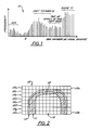
- a histogram 10 in Figure 1 plots the frequency (i.e., number of occurrences) of each respective voxel density of a slice into a plurality of bins.
- Figure 2 shows a voxel grid 15 superimposed over a coronal cross section of a portion of a head including bone 11 and soft tissue 13 (e.g., skin and brain matter).
- Tomographic data resulting from a diagnostic imaging scan according to Figure 2 will comprise a 3-D matrix of density values each corresponding to a respective voxel in grid 15.
- Axial slices 15a - 15h are shown in cross section and have a slice thickness such that a single voxel is large enough to contain structures of different types. Each voxel density will reflect the average tissue density within the entire voxel. Thus, in the area 12 at the top of the skull bones, voxel densities are low even with bone present due to the partial filling of voxels by bone.
- bone 11 occupies the upper end of the histogram due to its high CT density, while soft tissue with low CT densities are below bone in the histogram.
- Voxels in area 12 at the top of the skull have intermediate density values because they are partially filled with bone and partially filled with soft tissue or air.
- a threshold e.g., a particular bin number
- all voxels greater than the threshold are included in the object and all voxels less than the threshold are excluded from the object.
- each area of the histogram als contains noise (i.e., extraneous information).
- the noise is slice dependent such that slices containing more dense structures have more noise voxels. If partial volume artifacts were avoided by merely lowering the threshold, the noise would be greatly increased in the final image.
- the above problems are solved by use of a threshold value which varies from slice to slice or even voxel to voxel.
- the threshold value is lower for the slices including the top of the skull than for the remaining slices.
- the same result can be obtained with a single constant threshold by selectively weighting the voxel densities within the slices. For example, voxel densities in the slices including the top of the skull can be multiplied by a weighting coefficient which increases the density values.
- a part of a 3-D tomographic array 21 is shown including a plurality of cubes 22 defined by nodes 23 connected by edges 24.
- Each node 23 represents a signal amplitude of a voxel (i.e., data point) of tomographic data and each edge 24 represents the distance from one voxel to its neighbor.
- edges 24 are typically not all of equal length since slice spacing usually does not equal pixel spacing. Pixel spacings P and Q and slice spacing S are shown for cube 12.
- each large cube containing the surface to be displayed (as determined by comparisons with a threshold) is subdivided by integer factors (greater than or equal to zero) into a number of subcubes.
- the vertices of the subcubes are compared to the threshold (or thresholds) corresponding to the slice under consideration in order to identify subcubes through which the surface passes.
- the subcube location and normalized gradient for the subcube center are concatenated resulting in a directed point.
- the process of subdivision uses a large cube and adjacent points as shown in Figure 4.
- Cubically adjacent voxels from the tomographic data are selected to represent the vertices V1-V8 of the large cube.
- Points W1-W24 are adjacent to V1-V8 and are used in conjunction with V1-V8 to calculate the gradients at the vertices of the large cube. Interpolation can then be performed on the cube and the gradients.
- Figure 5 shows examples of gradients associated with the vertices of a cube.
- Figure 6 represents interpolated subcubes and gradient normals which define the subcubes within the large cube.
- Figure 7 shows subcubes having different interpolation factors along different axes.
- a large cube i.e., marching cube
- f(x,y,z) namely [f(i,j,k), f(i+1,j,k), f(i,j+1,k), f(i+1,j+1,k), f(i,j,k+1), f(i+1,j,k+1), f(i,j+1,k+1), f(i+1,j+1,k+1), f(i+1,j+1,k+1)]
- i is the row
- j is the column
- k is the slice in the tomographic data.
- the eight vertices are compared to a threshold T in step 28.
- the threshold T is a function of slice k, or T(k).
- the threshold can further be a two-or three-dimensional function if desired, or T(i,j,k).
- threshold T can be held constant while the vertices compared to the constant threshold are first multiplied by a weighting coefficient which has a value dependent on the location (e.g., slice number) of each respective vertex. If all of the values for the vertices are greater than the threshold or if all are less than the threshold, then the surface does not pass through the large cube, and so the method checks to see if all large cubes have been processed in step 29. If finished, then the method halts at stop block 30 and other functions may then be performed (such as rendering and display of the defined surface). Otherwise, a return is made to step 26 to begin processing another large cube.
- step 28 determines that there are vertices both above and below the threshold (or, alternatively, both inside and outside a slice-dependent threshold range)
- gradient values are calculated at each of the large cube vertices in step 31.
- c1 1 / (2 * PIXEL x )
- c2 1 / (2 * PIXEL y )
- c3 1 / (z k+1 - z k-1 )
- PIXEL x and PIXEL y are the pixel spacings within the slice along the x- and y-axes, respectively
- (z k+1 - z k-1 ) is the distance between the two slices on either side of slice k.
- step 32 density values are found for the subcube vertices by tri-linear interpolation.
- the vertices of each large cube v(i,j,k) are denoted as v(0,0,0), V(1,0,0), v(0,1,0), v(1,1,0), v(0,0,1), v(1,0,1), v(0,1,1), and v(1,1,1).
- step 33 gradient values are calculated for the center of each subcube using tri-linear interpolation of the gradients at the large cube vertices g x , g y and g z .
- a subcube is defined by the eight-tuple [f′(I,J,K), f′(I+1,J,K), f′(I,J+1,K), f′(I+1,J+1,K), f′(I,J,K+1), f′(I+1,J,K+1), f′(I,J+1,K+1), f′(I+1,J+1,K+1), f′(I+1,J+1,K+1)].
- step 35 the current subcube is tested against its appropriate threshold. If all subcube vertices are not either above or all below the threshold, then the location of the subcube and its normalized gradient are output to a list as a directed point in step 36, otherwise a check for completion is done in step 37.
- the gradient output to the list during step 36 is a normalized gradient defined as G(I,J,K)/
- step 37 branches back to step 29 to process the next large cube.
- a data acquisition system 50 collects tomographic data slices of a subject under control of a computer 39.
- An operator provides commands via a command interface 38 to computer 39 in order to control slice-dependent threshold values or slice dependent weighting coefficients, for example.
- Computer 39 reconstructs two-dimensional tomographic images from the data collected by data acquisition system 50.
- the tomographic images are provided to a surface generator 40.
- Computer 39 also provide values for the interpolation factors for forming subcubes to surface generator 40.
- Surface generator 40 implements the dividing cubes method to generate a number of directed points defining the surface that are fed to a display processor 41 which includes a Current-Transformation-Matrix (CTM) generator 42 and a renderer 43.
- CTM Current-Transformation-Matrix
- CTM generator 42 receives a viewer's commands via a command processor 45 for scaling, moving and rotating the object and forms the CTM which is provided to renderer 43 to operate on the directed points.
- Renderer 43 synthesizes the 3-D image (including projecting directed points onto 3-D pixels and determining shading of illuminated pixels) which is rasterized and sent to display 44 which could be a cathode-ray tube (CRT), for example.
- CTR cathode-ray tube
Landscapes
- Physics & Mathematics (AREA)
- Engineering & Computer Science (AREA)
- Nuclear Medicine, Radiotherapy & Molecular Imaging (AREA)
- General Physics & Mathematics (AREA)
- Health & Medical Sciences (AREA)
- High Energy & Nuclear Physics (AREA)
- Signal Processing (AREA)
- Radiology & Medical Imaging (AREA)
- General Health & Medical Sciences (AREA)
- Condensed Matter Physics & Semiconductors (AREA)
- Vascular Medicine (AREA)
- Theoretical Computer Science (AREA)
- Apparatus For Radiation Diagnosis (AREA)
- Image Processing (AREA)
- Ultra Sonic Daignosis Equipment (AREA)
- Image Generation (AREA)
Applications Claiming Priority (2)
| Application Number | Priority Date | Filing Date | Title |
|---|---|---|---|
| US07/261,533 US4914589A (en) | 1988-10-24 | 1988-10-24 | Three-dimensional images obtained from tomographic data using a variable threshold |
| US261533 | 1988-10-24 |
Publications (2)
| Publication Number | Publication Date |
|---|---|
| EP0366387A2 true EP0366387A2 (fr) | 1990-05-02 |
| EP0366387A3 EP0366387A3 (fr) | 1992-03-25 |
Family
ID=22993744
Family Applications (1)
| Application Number | Title | Priority Date | Filing Date |
|---|---|---|---|
| EP19890310889 Ceased EP0366387A3 (fr) | 1988-10-24 | 1989-10-23 | Obtention d'images tridimensionnelles à partir de données tomographiques |
Country Status (4)
| Country | Link |
|---|---|
| US (1) | US4914589A (fr) |
| EP (1) | EP0366387A3 (fr) |
| JP (1) | JPH0731739B2 (fr) |
| IL (1) | IL91951A (fr) |
Cited By (10)
| Publication number | Priority date | Publication date | Assignee | Title |
|---|---|---|---|---|
| EP0506302A1 (fr) * | 1991-03-25 | 1992-09-30 | General Electric Company | Méthodes de projection pour produire des images à deux dimensions à partir de données à trois dimensions |
| WO1998024064A1 (fr) * | 1996-11-27 | 1998-06-04 | Voxel | Procede et dispositif d'evaluation rapide de parametres de traitement informatique |
| EP1062555A1 (fr) * | 1998-02-11 | 2000-12-27 | Analogic Corporation | Appareil de tomodensitometrie et procede de classement d'objets |
| US6317509B1 (en) | 1998-02-11 | 2001-11-13 | Analogic Corporation | Computed tomography apparatus and method for classifying objects |
| CN1127700C (zh) * | 1996-11-27 | 2003-11-12 | 通用电气公司 | 通过消除主结构增强数据显象能力 |
| WO2007093066A1 (fr) * | 2006-02-16 | 2007-08-23 | Eidgenössische Materialprüfungs- Und Forschungsanstalt (Empa) | Reconstruction d'images par tomodensitométrie |
| WO2007131723A1 (fr) * | 2006-05-11 | 2007-11-22 | Werth Messtechnik Gmbh | Procédé de mesure d'un corps solide |
| WO2008074681A1 (fr) * | 2006-12-19 | 2008-06-26 | Siemens Aktiengesellschaft | Procédé et dispositif de formation d'une image radiotomographique de synthèse en 3d |
| DE19746936B4 (de) * | 1996-11-01 | 2008-09-04 | General Electric Co. | Schnelle Unterteilung von Herzbildern |
| DE102006022104B4 (de) * | 2006-05-11 | 2012-09-06 | Fraunhofer-Gesellschaft zur Förderung der angewandten Forschung e.V. | Vorrichtung zur dreidimensionalen Vermessung eines Festkörpers |
Families Citing this family (29)
| Publication number | Priority date | Publication date | Assignee | Title |
|---|---|---|---|---|
| US5079699A (en) * | 1987-11-27 | 1992-01-07 | Picker International, Inc. | Quick three-dimensional display |
| US4984157A (en) * | 1988-09-21 | 1991-01-08 | General Electric Company | System and method for displaying oblique planar cross sections of a solid body using tri-linear interpolation to determine pixel position dataes |
| FR2656129B1 (fr) * | 1989-12-20 | 1992-03-13 | Gen Electric Cgr | Procede de reconstruction multi-echelle de l'image de la structure d'un corps. |
| JP2892430B2 (ja) * | 1990-03-28 | 1999-05-17 | 株式会社日立製作所 | 物理量の表示方法及びその装置 |
| US5201035A (en) * | 1990-07-09 | 1993-04-06 | The United States Of America As Represented By The Secretary Of The Air Force | Dynamic algorithm selection for volume rendering, isocontour and body extraction within a multiple-instruction, multiple-data multiprocessor |
| JP2643596B2 (ja) * | 1990-11-29 | 1997-08-20 | 株式会社日立製作所 | スカラ量分布表示方法 |
| DE4117117A1 (de) * | 1991-05-25 | 1992-11-26 | Hoehne Karl Heinz Prof Dr | Dreidimensionale darstellung von raeumlichen strukturen |
| US5357429A (en) * | 1992-04-02 | 1994-10-18 | Levy Richard A | Three-dimensional model generation using multiple angle tomographic scan planes |
| US5559712A (en) * | 1992-09-18 | 1996-09-24 | Kabushiki Kaisha Toshiba | Three-dimensional model forming device |
| US5517602A (en) * | 1992-12-03 | 1996-05-14 | Hewlett-Packard Company | Method and apparatus for generating a topologically consistent visual representation of a three dimensional surface |
| US5473747A (en) * | 1993-02-08 | 1995-12-05 | International Business Machines Corporation | Method and apparatus for identifying features in a multidimensional data set |
| US5368033A (en) * | 1993-04-20 | 1994-11-29 | North American Philips Corporation | Magnetic resonance angiography method and apparatus employing an integration projection |
| JP3207971B2 (ja) * | 1993-06-25 | 2001-09-10 | 富士通株式会社 | 最適骨組及び板組構造の設計方法 |
| US5426684A (en) * | 1993-11-15 | 1995-06-20 | Eastman Kodak Company | Technique for finding the histogram region of interest for improved tone scale reproduction of digital radiographic images |
| US5761333A (en) * | 1995-01-31 | 1998-06-02 | General Electric Company | Contrast enhancement for CT systems |
| US5533091A (en) * | 1995-04-28 | 1996-07-02 | General Electric Company | Noise suppression algorithm and system |
| US5825364A (en) * | 1996-04-18 | 1998-10-20 | Electronic Data Systems Corporation | System and method for constructing a three dimensional model from two dimensional images using poissan probability |
| US6246784B1 (en) | 1997-08-19 | 2001-06-12 | The United States Of America As Represented By The Department Of Health And Human Services | Method for segmenting medical images and detecting surface anomalies in anatomical structures |
| US6026171A (en) * | 1998-02-11 | 2000-02-15 | Analogic Corporation | Apparatus and method for detection of liquids in computed tomography data |
| US6308161B1 (en) * | 1998-03-20 | 2001-10-23 | International Business Machines Corporation | System and method for business process space definition |
| US6396939B1 (en) | 1998-05-28 | 2002-05-28 | Orthosoft Inc. | Method and system for segmentation of medical images |
| US6701000B1 (en) * | 1999-04-30 | 2004-03-02 | General Electric Company | Solution to detector lag problem in a solid state detector |
| US7477770B2 (en) * | 2001-12-05 | 2009-01-13 | The Trustees Of The University Of Pennsylvania | Virtual bone biopsy |
| US7091971B2 (en) | 2001-10-29 | 2006-08-15 | Ati Technologies, Inc. | System, method, and apparatus for multi-level hierarchical Z buffering |
| US7260250B2 (en) * | 2002-09-30 | 2007-08-21 | The United States Of America As Represented By The Secretary Of The Department Of Health And Human Services | Computer-aided classification of anomalies in anatomical structures |
| US7098910B2 (en) * | 2003-05-14 | 2006-08-29 | Lena Petrovic | Hair rendering method and apparatus |
| US7468730B2 (en) * | 2004-03-25 | 2008-12-23 | Pixar | Volumetric hair simulation |
| US7295135B2 (en) * | 2006-02-06 | 2007-11-13 | Trutrak Flight Systems, Inc. | Flight information system |
| US20110224550A1 (en) * | 2008-11-14 | 2011-09-15 | Hitachi Medical Corporation | Ultrasound diagnostic system and method for generating standard image data for the ultrasound diagnostic system |
Citations (2)
| Publication number | Priority date | Publication date | Assignee | Title |
|---|---|---|---|---|
| EP0283255A2 (fr) * | 1987-03-18 | 1988-09-21 | General Electric Company | Dispositif d'affichage d'images avec ajustement automatique de l'image |
| EP0287409A1 (fr) * | 1987-04-03 | 1988-10-19 | General Electric Cgr S.A. | Procédé de calcul et de représentation d'images de vues d'un objet |
-
1988
- 1988-10-24 US US07/261,533 patent/US4914589A/en not_active Expired - Fee Related
-
1989
- 1989-10-11 IL IL91951A patent/IL91951A/xx not_active IP Right Cessation
- 1989-10-23 EP EP19890310889 patent/EP0366387A3/fr not_active Ceased
- 1989-10-24 JP JP1275146A patent/JPH0731739B2/ja not_active Expired - Lifetime
Patent Citations (2)
| Publication number | Priority date | Publication date | Assignee | Title |
|---|---|---|---|---|
| EP0283255A2 (fr) * | 1987-03-18 | 1988-09-21 | General Electric Company | Dispositif d'affichage d'images avec ajustement automatique de l'image |
| EP0287409A1 (fr) * | 1987-04-03 | 1988-10-19 | General Electric Cgr S.A. | Procédé de calcul et de représentation d'images de vues d'un objet |
Cited By (14)
| Publication number | Priority date | Publication date | Assignee | Title |
|---|---|---|---|---|
| EP0506302A1 (fr) * | 1991-03-25 | 1992-09-30 | General Electric Company | Méthodes de projection pour produire des images à deux dimensions à partir de données à trois dimensions |
| US5233299A (en) * | 1991-03-25 | 1993-08-03 | General Electric Company | Projection methods for producing two-dimensional images from three-dimensional data |
| DE19746936B4 (de) * | 1996-11-01 | 2008-09-04 | General Electric Co. | Schnelle Unterteilung von Herzbildern |
| WO1998024064A1 (fr) * | 1996-11-27 | 1998-06-04 | Voxel | Procede et dispositif d'evaluation rapide de parametres de traitement informatique |
| US6123733A (en) * | 1996-11-27 | 2000-09-26 | Voxel, Inc. | Method and apparatus for rapidly evaluating digital data processing parameters |
| CN1127700C (zh) * | 1996-11-27 | 2003-11-12 | 通用电气公司 | 通过消除主结构增强数据显象能力 |
| US6317509B1 (en) | 1998-02-11 | 2001-11-13 | Analogic Corporation | Computed tomography apparatus and method for classifying objects |
| EP1062555A4 (fr) * | 1998-02-11 | 2001-05-23 | Analogic Corp | Appareil de tomodensitometrie et procede de classement d'objets |
| EP1062555A1 (fr) * | 1998-02-11 | 2000-12-27 | Analogic Corporation | Appareil de tomodensitometrie et procede de classement d'objets |
| WO2007093066A1 (fr) * | 2006-02-16 | 2007-08-23 | Eidgenössische Materialprüfungs- Und Forschungsanstalt (Empa) | Reconstruction d'images par tomodensitométrie |
| WO2007131723A1 (fr) * | 2006-05-11 | 2007-11-22 | Werth Messtechnik Gmbh | Procédé de mesure d'un corps solide |
| DE102006022104B4 (de) * | 2006-05-11 | 2012-09-06 | Fraunhofer-Gesellschaft zur Förderung der angewandten Forschung e.V. | Vorrichtung zur dreidimensionalen Vermessung eines Festkörpers |
| DE102006022103B4 (de) * | 2006-05-11 | 2013-05-29 | Werth Messtechnik Gmbh | Verfahren zum Vermessen eines Festkörpers |
| WO2008074681A1 (fr) * | 2006-12-19 | 2008-06-26 | Siemens Aktiengesellschaft | Procédé et dispositif de formation d'une image radiotomographique de synthèse en 3d |
Also Published As
| Publication number | Publication date |
|---|---|
| IL91951A (en) | 1992-12-01 |
| JPH02178786A (ja) | 1990-07-11 |
| JPH0731739B2 (ja) | 1995-04-10 |
| US4914589A (en) | 1990-04-03 |
| IL91951A0 (en) | 1990-06-10 |
| EP0366387A3 (fr) | 1992-03-25 |
Similar Documents
| Publication | Publication Date | Title |
|---|---|---|
| US4914589A (en) | Three-dimensional images obtained from tomographic data using a variable threshold | |
| US4953087A (en) | Three-dimensional images obtained from tomographic data having unequally spaced slices | |
| US4903202A (en) | Three-dimensional object removal via connectivity | |
| US4989142A (en) | Three-dimensional images obtained from tomographic slices with gantry tilt | |
| US6978039B2 (en) | Method and system for segmentation of medical images | |
| US5412563A (en) | Gradient image segmentation method | |
| US4831528A (en) | Apparatus and method for improvement of 3D images derived from tomographic data | |
| US4905148A (en) | Three-dimensional surface representation using connectivity method without leaks | |
| US5187658A (en) | System and method for segmenting internal structures contained within the interior region of a solid object | |
| US5166876A (en) | System and method for detecting internal structures contained within the interior region of a solid object | |
| US5602891A (en) | Imaging apparatus and method with compensation for object motion | |
| US4835688A (en) | Three-dimensional image processing apparatus | |
| US4729098A (en) | System and method employing nonlinear interpolation for the display of surface structures contained within the interior region of a solid body | |
| EP1653858B1 (fr) | Mappage des arteres coronaires sur une sphere | |
| EP1365356A2 (fr) | Algorithme de segmentation semiautomatique pour des images oncologiques d'animaux familiers | |
| CA1315902C (fr) | Minimisation de points diriges generes par la methode des cubes diviseurs tridimensionnels | |
| US20020012478A1 (en) | Image processing electronic device for detecting dimensional variations | |
| EP0216156A2 (fr) | Système de division de cubes et méthode pour l'affichage de structures de surface contenues dans la région interne d'un corps solide | |
| US7136516B2 (en) | Method and system for segmenting magnetic resonance images | |
| CA1257023A (fr) | Systeme et methode a interpolation non lineaire pour afficher la structure de surfaces se trouvant a l'interieur d'un corps solide | |
| US20040161144A1 (en) | Method for producing an image | |
| EP0318293B1 (fr) | Dispositif et procédé de traitement de données tomographiques | |
| EP0354026B1 (fr) | Affichage en trois dimensions de données tomographiques | |
| EP0373854B1 (fr) | Système et méthode pour la détection de structures internes contenues à l'intérieur d'un objet solide | |
| EP0318291B1 (fr) | Dispositif et méthode pour la génération d'images à partir de données tomographiques |
Legal Events
| Date | Code | Title | Description |
|---|---|---|---|
| PUAI | Public reference made under article 153(3) epc to a published international application that has entered the european phase |
Free format text: ORIGINAL CODE: 0009012 |
|
| AK | Designated contracting states |
Kind code of ref document: A2 Designated state(s): DE FR GB NL |
|
| PUAL | Search report despatched |
Free format text: ORIGINAL CODE: 0009013 |
|
| AK | Designated contracting states |
Kind code of ref document: A3 Designated state(s): DE FR GB NL |
|
| 17P | Request for examination filed |
Effective date: 19920824 |
|
| 17Q | First examination report despatched |
Effective date: 19950505 |
|
| GRAG | Despatch of communication of intention to grant |
Free format text: ORIGINAL CODE: EPIDOS AGRA |
|
| STAA | Information on the status of an ep patent application or granted ep patent |
Free format text: STATUS: THE APPLICATION HAS BEEN REFUSED |
|
| 18R | Application refused |
Effective date: 19970502 |