EP0366339A2 - Dispositif de protection multiphasé pour moteur - Google Patents
Dispositif de protection multiphasé pour moteur Download PDFInfo
- Publication number
- EP0366339A2 EP0366339A2 EP89310693A EP89310693A EP0366339A2 EP 0366339 A2 EP0366339 A2 EP 0366339A2 EP 89310693 A EP89310693 A EP 89310693A EP 89310693 A EP89310693 A EP 89310693A EP 0366339 A2 EP0366339 A2 EP 0366339A2
- Authority
- EP
- European Patent Office
- Prior art keywords
- disc
- heater
- header
- extending
- heaters
- Prior art date
- Legal status (The legal status is an assumption and is not a legal conclusion. Google has not performed a legal analysis and makes no representation as to the accuracy of the status listed.)
- Granted
Links
Images
Classifications
-
- H—ELECTRICITY
- H01—ELECTRIC ELEMENTS
- H01H—ELECTRIC SWITCHES; RELAYS; SELECTORS; EMERGENCY PROTECTIVE DEVICES
- H01H37/00—Thermally-actuated switches
- H01H37/02—Details
- H01H37/32—Thermally-sensitive members
- H01H37/52—Thermally-sensitive members actuated due to deflection of bimetallic element
- H01H37/54—Thermally-sensitive members actuated due to deflection of bimetallic element wherein the bimetallic element is inherently snap acting
- H01H37/5418—Thermally-sensitive members actuated due to deflection of bimetallic element wherein the bimetallic element is inherently snap acting using cantilevered bimetallic snap elements
-
- H—ELECTRICITY
- H01—ELECTRIC ELEMENTS
- H01H—ELECTRIC SWITCHES; RELAYS; SELECTORS; EMERGENCY PROTECTIVE DEVICES
- H01H37/00—Thermally-actuated switches
- H01H37/004—Thermally-actuated switches with thermal image
-
- H—ELECTRICITY
- H01—ELECTRIC ELEMENTS
- H01H—ELECTRIC SWITCHES; RELAYS; SELECTORS; EMERGENCY PROTECTIVE DEVICES
- H01H37/00—Thermally-actuated switches
- H01H37/02—Details
- H01H37/12—Means for adjustment of "on" or "off" operating temperature
- H01H37/28—Means for adjustment of "on" or "off" operating temperature by adjustment of the position of the fixed contact
-
- H—ELECTRICITY
- H01—ELECTRIC ELEMENTS
- H01H—ELECTRIC SWITCHES; RELAYS; SELECTORS; EMERGENCY PROTECTIVE DEVICES
- H01H9/00—Details of switching devices, not covered by groups H01H1/00 - H01H7/00
- H01H9/0072—Details of switching devices, not covered by groups H01H1/00 - H01H7/00 particular to three-phase switches
Definitions
- This invention relates generally to temperature responsive switches and more particularly to hermetic, three phase protectors for use in motor protection circuits or other similar electrical apparatus protection circuits. It is known to provide switches in which a temperature responsive snap acting disc is used in conjunction with heaters acting as thermal analogs of motor windings so that upon selected conditions the heat generated in the motor or in any or all of the heaters cause the snap acting disc to snap thereby opening movable contacts operatively connected to the disc thereby deenergizing the protected apparatus. For example, such switches are shown and described in U.S. Patent Nos. 3,452,313, 4,231,010 and 4,555,686.
- Another object of the invention is the provision of a temperature responsive three phase protector which is responsive to each of the three phases of apparatus being protected. Yet another object is the provision of a protector whose calibration is relatively insensitive to deflections in the cap member enclosing the switch.
- a generally oval metallic header plate mounts a pair of terminal pins each of which in turn mounts an end of an elongated strip heater.
- the heaters extend away from the header and mount at their distal free ends a stationary contact.
- a rigid support member, attached to the header intermediate the terminal pins, extends away from the header and mounts a third heater which in turn extends back toward the header.
- the third heater is structurally reinforced by a flange along its length to which the body portion of a welding slug is welded at the free end of the heater.
- a thermostatic snap acting disc is attached to the underside of the head of the welding slug to cantilever mount the disc.
- the disc is generally bell shaped having a head portion where the disc is mounted and having a mouth portion where two movable electrical contacts are mounted at opposite ends of the mouth which are adapted to move into and out of engagement with the stationary contacts.
- the movable contacts are preferably located slightly closer to the header than are the stationary contacts prior to device calibration.
- the head portion has a relatively straight bending edge contiguous to the disc which extends in a direction generally parallel to an imaginary line drawn through the centers of the movable contacts.
- the support member is provided with a pair of arms extending laterally from the support member to provide mounting pads disposed beneath the free distal ends of the first and second heaters.
- a self tapping calibration screw is received in an aperture in each mounting pad in alignment with the free distal end of a respective heater.
- An electrically insulating pad is interposed between each screw and its respective heater.
- the device is calibrated by taking a switch assembly, prior to the attachment of a cover with the disc in an upwardly convex surface configuration, heating the assembly to a selected calibration temperature allowing the disc to creep to a stabilized position with the contacts open, independently turning the screws, either sequentially or simultaneously, until one stationary contact engages its movable contact and continuing turning only the other screw until its stationary contact engages its movable contact. Then both screws are turned the same amount until the disc snaps to the opposite upwardly concave surface configuration with the movable contacts out of engagement with the stationary contacts.
- the cover member which may be formed of a high strength low alloy steel to provide suitable pressure capability required for high pressure environments has an outwardly flared portion at its mouth which receives therein the outer edge of the header and is welded thereto to hermetically seal the protector thereby minimizing space occupied by the package.
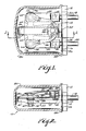
- Pins 18, 20 have a longitudinal axes generally parallel to one another and extending away from the header in a direction generally perpendicular to an inside face surface 26 of header 12 to form at their distal free ends mounts for elongated strip heater members 28, 30 welded thereto as indicated at 32, 34 respectively which in turn extend in a direction generally parallel to the longitudinal axes of the terminal members.
- Stationary contacts 36, 38 are attached to the free distal end of heater members 28, 30 by any suitable means, as by welding.
- a rigid support member 33 of steel or other suitable material has a leg portion 35 attached to header 12 in a suitable manner, as by welding, and an elongated leg portion 37 disposed generally 90 degrees relative leg to portion 35 and extending away from face surface 26 in a direction generally parallel to the longitudinal axes of the terminal members.
- a strip heater 39 is attached to the free distal end 40 of support member 33 in any conventional manner, as by welding, and extends back toward header 12 culminating at a free end 42 spaced from leg portion 35. Free end 42 of heater 39 mounts thereon a welding slug 44 which in turn cantilever mounts one end of a snap acting bimetallic disc 46 by welding the disc as shown at 47 to head 48 adjacent the periphery of slug 44. That is, disc 46 is provided with an aperture through which slug 44 is received so that the disc can be welded to head 48.
- Thermostatic disc 46 is provided with first and second movable electrical contacts 50, 52 attached to the underside of the disc in a conventional manner, as by welding at opposed sides of the distal free end of the disc. Contacts 50, 52 are adapted to move into and out of engagement with stationary contacts 36, 38 respectively upon snapping of disc 46.
- Head 48, disposed on the top surface of disc 46 is provided with a relatively straight bending edge 54 about which the disc bends when snapping to a contacts open configuration thereby distributing the bending stresses in the disc all along the length of the edge and keeping the stresses away from the welded portion of the disc.
- welds 47 are disposed on the sides and free end portions of disc 46 but not adjacent bending edge 54 so that bending against any welds is avoided.
- Bending edge 54 extends in a direction generally parallel to an imaginary line drawn through the centers of movable contacts 50, 52 or, stated in another way, perpenducular to an imaginary line extending between the opposite fixed and free ends of the disc. Placing head 48 on the top surface of the disc so that bending edge 54 can be utilized minimizes calibration shifts in the disc which would otherwise occurr, particularly over time without having a calibration member engaging the central portion of the disc.
- disc 46 is shaped generally as a bell with the cantilever mount located at the head of the bell and the movable contacts located at opposite sides of the mouth of the bell.
- heater 39 is preferably provided with a reinforcing flange 56.
- Flange 56 is shown mounting welding slug 44 as by welding thereto and for that purpose extends to a greater height, as shown at 58, than the remainder of the flange, however, if desired, slug 44 can be welded directly to the flat portion of heater 39.
- Support member 33 is provided with laterally extending arms 60, 62 which are provided with calibration screw mounting pads 64, 66 respectively disposed beneath the distal end of strip heaters 28, 30. Calibration screws 72, 74 are received in respective apertures formed in mounting pads 64, 66 and are used to transmit a bending force to the distal free end of the heaters to thereby adjust the vertical position of the respective stationary contacts.
- Support member 33 is electrically isolated from heaters 28 and 30 by insulative pads 76 and 78 disposed intermediate the screws and their respective heaters. The insulative pads are mounted in any convenient manner as by forming a detent portion to receive the end of the calibration screw to lock them laterally in position.
- Movable contacts 50, 52 are located slightly closer to header 12 than are stationary contacts 36, 38 and come into closer vertical alignment during calibration.
- the protector is calibrated by taking a switch assembly before attachment of the enclosing cap with the disc at an at rest upwardly convex surface configuration, heating the assembly to a selected calibration temperature allowing the disc to creep to a stabilized position with the contacts open, separately (either simultaneously or sequentially) screwing in the calibrating screws until one stationary contact engages its respective movable contact and continuing turning only the other screw until its stationary contact engages its movable contact.
- the screws are then turned together the same amount until the disc snaps to the opposite upwardly concave surface configuration with the movable contacts out of engagement with the stationary contacts. Calibrating in this manner ensures that when the disc snaps to the upwardly convex configuration upon being heated to a selected temperature both movable contacts will simultaneously move out of engagement with their respective stationary contacts as required for proper operation.
- a suitable cap member 80 formed for example of a high strength alloy encloses the volume around the switch structure providing suitable strength enabling the device to be placed in high pressure environments. Header 12 is welded internally to flange 82 of cap member 80 to minimize the profile of the protector.
- a switch made in accordance with the invention offers a number of advantages.
- the parallel orientation of the terminal pins and the thermostatic disc permits placement of the protector on the windings in such a manner as to reduce its profile on the motor, that is the device does not stick out from the motor as much as conventional protectors.
- This profile is further minimized by welding the header on the internal surface of the flared cap flange.
- the use of a bending edge on top of the disc mounting one or more movable contacts results in improved performance of a cantilever mounted disc.
- the particular mounting of the disc without having a member contacting the center of the disc as in conventional three phase protectors allows wider parameters for discs which can be used for given motor ratings due to the ability to calibrate with the dual screws thereby facilitating manufacture of the protector as well as reducing the number of parts used in conventional protectors.
- Use of the dual screw calibration allows for compensation of uneven contact gaps produced during device assembly thereby making manufacture less expensive due to having wider acceptable tolerances.
- the use of the self-tapping screws avoids the need for a locking mechanism again reducing the number of parts required for the device.
- the three heaters employed are of generally the same length with a heater connected in each of the three phases thereby providing equal trip time performance for each phase for protection in single phasing conditions.
Landscapes
- Physics & Mathematics (AREA)
- Thermal Sciences (AREA)
- Thermally Actuated Switches (AREA)
Applications Claiming Priority (2)
| Application Number | Priority Date | Filing Date | Title |
|---|---|---|---|
| US07/264,122 US4866408A (en) | 1988-10-28 | 1988-10-28 | Multiphase motor protector apparatus |
| US264122 | 1988-10-28 |
Publications (3)
| Publication Number | Publication Date |
|---|---|
| EP0366339A2 true EP0366339A2 (fr) | 1990-05-02 |
| EP0366339A3 EP0366339A3 (fr) | 1992-04-08 |
| EP0366339B1 EP0366339B1 (fr) | 1995-03-22 |
Family
ID=23004683
Family Applications (1)
| Application Number | Title | Priority Date | Filing Date |
|---|---|---|---|
| EP89310693A Expired - Lifetime EP0366339B1 (fr) | 1988-10-28 | 1989-10-18 | Dispositif de protection multiphasé pour moteur |
Country Status (4)
| Country | Link |
|---|---|
| US (1) | US4866408A (fr) |
| EP (1) | EP0366339B1 (fr) |
| JP (1) | JP2599797B2 (fr) |
| DE (1) | DE68921841T2 (fr) |
Cited By (1)
| Publication number | Priority date | Publication date | Assignee | Title |
|---|---|---|---|---|
| CN100499005C (zh) * | 2004-05-27 | 2009-06-10 | 森萨塔科技麻省公司 | 用于电气设备的保护器 |
Families Citing this family (15)
| Publication number | Priority date | Publication date | Assignee | Title |
|---|---|---|---|---|
| DE19509656C2 (de) * | 1995-03-17 | 1997-01-16 | Radbruch Jens Dipl Ing | Temperaturschutzschalter |
| CA2208910C (fr) * | 1996-07-04 | 2001-11-06 | Ubukata Industries Co., Ltd. | Systeme de protection thermique pour moteurs electriques |
| US5808539A (en) * | 1996-10-10 | 1998-09-15 | Texas Instruments Incorporated | Temperature responsive snap acting control assembly, device using such assembly and method for making |
| US6542062B1 (en) * | 1999-06-11 | 2003-04-01 | Tecumseh Products Company | Overload protector with control element |
| US6498560B2 (en) * | 2001-03-23 | 2002-12-24 | Emerson Electric Co. | Protector assembly and method for electrically insulating a thermally responsive protector from a motor winding of an electric motor |
| US7298239B2 (en) * | 2002-05-07 | 2007-11-20 | Ubukata Industries Co., Ltd. | Thermal protector |
| DE102004036117B4 (de) * | 2004-07-24 | 2006-12-14 | Tmc Sensortechnik Gmbh | Thermobimetallschalter |
| US7535136B2 (en) * | 2006-02-22 | 2009-05-19 | Emerson Electric Co. | Protector mounting apparatus for protector mounted on the windings of a motor |
| JP4638942B2 (ja) * | 2006-10-30 | 2011-02-23 | ウチヤ・サーモスタット株式会社 | サーマルプロテクタ |
| US8492943B2 (en) * | 2006-10-31 | 2013-07-23 | Emerson Electric Co. | Protector mounting apparatus for protector mounted adjacent the windings of a motor |
| US8547196B2 (en) * | 2008-05-30 | 2013-10-01 | Ubukata Industries Co., Ltd. | Thermally responsive switch |
| US8264317B2 (en) * | 2008-11-05 | 2012-09-11 | Ubukata Industries Co., Ltd. | Protective device of three-phase motor |
| DE102011101862B4 (de) * | 2011-05-12 | 2012-12-13 | Thermik Gerätebau GmbH | Temperaturabhängiger Schalter mit Stromübertragungsglied |
| JP7280848B2 (ja) * | 2020-03-18 | 2023-05-24 | ボーンズ株式会社 | ブレーカー、安全回路及び2次電池パック |
| KR102787649B1 (ko) * | 2020-09-15 | 2025-03-28 | 가부시키가이샤 우부카타 세이사쿠쇼 | 모터 프로텍터 |
Family Cites Families (12)
| Publication number | Priority date | Publication date | Assignee | Title |
|---|---|---|---|---|
| US2676221A (en) * | 1948-12-14 | 1954-04-20 | Perfex Corp | Switching apparatus |
| DE1183162B (de) * | 1961-06-14 | 1964-12-10 | Busch Jaeger Duerener Metall | Elektrischer Waermeschalter mit einstellbarer Schaltfolge mehrerer Kontakte |
| US3148258A (en) * | 1961-09-26 | 1964-09-08 | Dales George Franklin | Thermostat with bimetal set in plastic |
| US3452313A (en) * | 1966-12-19 | 1969-06-24 | Texas Instruments Inc | Snap-acting thermostatic electric switch |
| US3431526A (en) * | 1967-01-03 | 1969-03-04 | Texas Instruments Inc | Miniature electrical switch |
| US3959762A (en) * | 1974-12-09 | 1976-05-25 | Texas Instruments Incorporated | Thermally responsive electrical switch |
| US4231010A (en) * | 1978-11-30 | 1980-10-28 | Texas Instruments Incorporated | Thermostatic switch employing a stud member for calibration of the switch |
| US4287499A (en) * | 1978-12-29 | 1981-09-01 | Texas Instruments Incorporated | Current interrupting apparatus having improved contact life |
| US4376926A (en) * | 1979-06-27 | 1983-03-15 | Texas Instruments Incorporated | Motor protector calibratable by housing deformation having improved sealing and compactness |
| US4389630A (en) * | 1980-03-15 | 1983-06-21 | Susumu Ubukatu | Snap action thermally responsive switch |
| US4555686A (en) * | 1984-05-29 | 1985-11-26 | Texas Instruments Incorporated | Snap-acting thermostatic switch assembly |
| US4780698A (en) * | 1987-04-30 | 1988-10-25 | Texas Instruments Incorporated | Circuit interrupter device and method for making |
-
1988
- 1988-10-28 US US07/264,122 patent/US4866408A/en not_active Expired - Lifetime
-
1989
- 1989-10-18 EP EP89310693A patent/EP0366339B1/fr not_active Expired - Lifetime
- 1989-10-18 DE DE68921841T patent/DE68921841T2/de not_active Expired - Fee Related
- 1989-10-26 JP JP1279627A patent/JP2599797B2/ja not_active Expired - Fee Related
Cited By (1)
| Publication number | Priority date | Publication date | Assignee | Title |
|---|---|---|---|---|
| CN100499005C (zh) * | 2004-05-27 | 2009-06-10 | 森萨塔科技麻省公司 | 用于电气设备的保护器 |
Also Published As
| Publication number | Publication date |
|---|---|
| DE68921841D1 (de) | 1995-04-27 |
| EP0366339A3 (fr) | 1992-04-08 |
| JP2599797B2 (ja) | 1997-04-16 |
| EP0366339B1 (fr) | 1995-03-22 |
| DE68921841T2 (de) | 1995-07-27 |
| US4866408A (en) | 1989-09-12 |
| JPH02270237A (ja) | 1990-11-05 |
Similar Documents
| Publication | Publication Date | Title |
|---|---|---|
| US4866408A (en) | Multiphase motor protector apparatus | |
| EP0676786B1 (fr) | Dispositif de protection compact | |
| US4490704A (en) | Thermally responsive switching device | |
| US5212465A (en) | Three-phase thermal protector | |
| US4843363A (en) | Three-phase thermal protector | |
| US3959762A (en) | Thermally responsive electrical switch | |
| US4555686A (en) | Snap-acting thermostatic switch assembly | |
| US7102481B2 (en) | Low current electric motor protector | |
| US4389630A (en) | Snap action thermally responsive switch | |
| JP2519549B2 (ja) | 熱応動開閉器 | |
| US6995647B2 (en) | Low current electric motor protector | |
| EP1855303A1 (fr) | Commutateur électrique thermiquement sensible | |
| US4914414A (en) | Thermally responsive switch | |
| CA1097395A (fr) | Regulateur de temperature pour appareils electriques | |
| US7109840B2 (en) | Protector for electrical apparatus | |
| US4013988A (en) | Hermetically sealed motor protector | |
| JP3046767B2 (ja) | サーマルプロテクタ | |
| JP3010141B2 (ja) | 密閉形電動圧縮機用プロテクタ | |
| JP2002352685A (ja) | サーマルプロテクタ | |
| JP3829882B2 (ja) | サーマルプロテクタ | |
| US4696579A (en) | Thermostat | |
| JP3992320B2 (ja) | サーマルプロテクタ | |
| JP2882768B2 (ja) | 三相用サーマルプロテクタ | |
| KR920006261Y1 (ko) | 열응동 스위치 | |
| JPH0316727B2 (fr) |
Legal Events
| Date | Code | Title | Description |
|---|---|---|---|
| PUAI | Public reference made under article 153(3) epc to a published international application that has entered the european phase |
Free format text: ORIGINAL CODE: 0009012 |
|
| AK | Designated contracting states |
Kind code of ref document: A2 Designated state(s): DE FR GB IT NL |
|
| PUAL | Search report despatched |
Free format text: ORIGINAL CODE: 0009013 |
|
| AK | Designated contracting states |
Kind code of ref document: A3 Designated state(s): DE FR GB IT NL |
|
| 17P | Request for examination filed |
Effective date: 19920721 |
|
| 17Q | First examination report despatched |
Effective date: 19940114 |
|
| GRAA | (expected) grant |
Free format text: ORIGINAL CODE: 0009210 |
|
| ITF | It: translation for a ep patent filed | ||
| AK | Designated contracting states |
Kind code of ref document: B1 Designated state(s): DE FR GB IT NL |
|
| REF | Corresponds to: |
Ref document number: 68921841 Country of ref document: DE Date of ref document: 19950427 |
|
| ET | Fr: translation filed | ||
| PLBE | No opposition filed within time limit |
Free format text: ORIGINAL CODE: 0009261 |
|
| STAA | Information on the status of an ep patent application or granted ep patent |
Free format text: STATUS: NO OPPOSITION FILED WITHIN TIME LIMIT |
|
| 26N | No opposition filed | ||
| REG | Reference to a national code |
Ref country code: GB Ref legal event code: IF02 |
|
| PGFP | Annual fee paid to national office [announced via postgrant information from national office to epo] |
Ref country code: NL Payment date: 20030916 Year of fee payment: 15 |
|
| PG25 | Lapsed in a contracting state [announced via postgrant information from national office to epo] |
Ref country code: NL Free format text: LAPSE BECAUSE OF NON-PAYMENT OF DUE FEES Effective date: 20050501 |
|
| NLV4 | Nl: lapsed or anulled due to non-payment of the annual fee |
Effective date: 20050501 |
|
| PG25 | Lapsed in a contracting state [announced via postgrant information from national office to epo] |
Ref country code: IT Free format text: LAPSE BECAUSE OF NON-PAYMENT OF DUE FEES;WARNING: LAPSES OF ITALIAN PATENTS WITH EFFECTIVE DATE BEFORE 2007 MAY HAVE OCCURRED AT ANY TIME BEFORE 2007. THE CORRECT EFFECTIVE DATE MAY BE DIFFERENT FROM THE ONE RECORDED. Effective date: 20051018 |
|
| PGFP | Annual fee paid to national office [announced via postgrant information from national office to epo] |
Ref country code: GB Payment date: 20060915 Year of fee payment: 18 |
|
| PGFP | Annual fee paid to national office [announced via postgrant information from national office to epo] |
Ref country code: DE Payment date: 20061031 Year of fee payment: 18 |
|
| REG | Reference to a national code |
Ref country code: GB Ref legal event code: 732E |
|
| REG | Reference to a national code |
Ref country code: FR Ref legal event code: TP |
|
| GBPC | Gb: european patent ceased through non-payment of renewal fee |
Effective date: 20071018 |
|
| PG25 | Lapsed in a contracting state [announced via postgrant information from national office to epo] |
Ref country code: DE Free format text: LAPSE BECAUSE OF NON-PAYMENT OF DUE FEES Effective date: 20080501 |
|
| REG | Reference to a national code |
Ref country code: FR Ref legal event code: ST Effective date: 20080630 |
|
| PGFP | Annual fee paid to national office [announced via postgrant information from national office to epo] |
Ref country code: FR Payment date: 20061003 Year of fee payment: 18 |
|
| PG25 | Lapsed in a contracting state [announced via postgrant information from national office to epo] |
Ref country code: GB Free format text: LAPSE BECAUSE OF NON-PAYMENT OF DUE FEES Effective date: 20071018 |
|
| PG25 | Lapsed in a contracting state [announced via postgrant information from national office to epo] |
Ref country code: FR Free format text: LAPSE BECAUSE OF NON-PAYMENT OF DUE FEES Effective date: 20071031 |