EP0366245B1 - Farbanzeigesystem und Röhre, versehen mit einer an zwei Elektroden modulierten Elektronenkanone - Google Patents
Farbanzeigesystem und Röhre, versehen mit einer an zwei Elektroden modulierten Elektronenkanone Download PDFInfo
- Publication number
- EP0366245B1 EP0366245B1 EP89309148A EP89309148A EP0366245B1 EP 0366245 B1 EP0366245 B1 EP 0366245B1 EP 89309148 A EP89309148 A EP 89309148A EP 89309148 A EP89309148 A EP 89309148A EP 0366245 B1 EP0366245 B1 EP 0366245B1
- Authority
- EP
- European Patent Office
- Prior art keywords
- lens
- electrode
- modulation
- beams
- electron
- Prior art date
- Legal status (The legal status is an assumption and is not a legal conclusion. Google has not performed a legal analysis and makes no representation as to the accuracy of the status listed.)
- Expired - Lifetime
Links
- 230000009977 dual effect Effects 0.000 title description 6
- 238000010894 electron beam technology Methods 0.000 claims description 62
- 230000004075 alteration Effects 0.000 claims description 3
- 201000009310 astigmatism Diseases 0.000 description 14
- 230000005405 multipole Effects 0.000 description 13
- 238000001125 extrusion Methods 0.000 description 6
- 230000000694 effects Effects 0.000 description 4
- 230000002093 peripheral effect Effects 0.000 description 4
- 238000010276 construction Methods 0.000 description 3
- 230000003068 static effect Effects 0.000 description 3
- OAICVXFJPJFONN-UHFFFAOYSA-N Phosphorus Chemical compound [P] OAICVXFJPJFONN-UHFFFAOYSA-N 0.000 description 2
- 238000000576 coating method Methods 0.000 description 2
- 150000001875 compounds Chemical class 0.000 description 2
- 239000011521 glass Substances 0.000 description 2
- 238000004519 manufacturing process Methods 0.000 description 2
- 239000011248 coating agent Substances 0.000 description 1
- 230000001447 compensatory effect Effects 0.000 description 1
- 230000008878 coupling Effects 0.000 description 1
- 238000010168 coupling process Methods 0.000 description 1
- 238000005859 coupling reaction Methods 0.000 description 1
- 230000000593 degrading effect Effects 0.000 description 1
- 238000003384 imaging method Methods 0.000 description 1
- 239000000463 material Substances 0.000 description 1
- 238000000034 method Methods 0.000 description 1
- 238000002156 mixing Methods 0.000 description 1
- 230000035515 penetration Effects 0.000 description 1
- 230000035945 sensitivity Effects 0.000 description 1
- 238000011144 upstream manufacturing Methods 0.000 description 1
- 238000004804 winding Methods 0.000 description 1
Images


Classifications
-
- H—ELECTRICITY
- H01—ELECTRIC ELEMENTS
- H01J—ELECTRIC DISCHARGE TUBES OR DISCHARGE LAMPS
- H01J29/00—Details of cathode-ray tubes or of electron-beam tubes of the types covered by group H01J31/00
- H01J29/46—Arrangements of electrodes and associated parts for generating or controlling the ray or beam, e.g. electron-optical arrangement
- H01J29/48—Electron guns
- H01J29/50—Electron guns two or more guns in a single vacuum space, e.g. for plural-ray tube
- H01J29/503—Three or more guns, the axes of which lay in a common plane
-
- H—ELECTRICITY
- H01—ELECTRIC ELEMENTS
- H01J—ELECTRIC DISCHARGE TUBES OR DISCHARGE LAMPS
- H01J2229/00—Details of cathode ray tubes or electron beam tubes
- H01J2229/48—Electron guns
- H01J2229/4834—Electrical arrangements coupled to electrodes, e.g. potentials
- H01J2229/4837—Electrical arrangements coupled to electrodes, e.g. potentials characterised by the potentials applied
- H01J2229/4841—Dynamic potentials
-
- H—ELECTRICITY
- H01—ELECTRIC ELEMENTS
- H01J—ELECTRIC DISCHARGE TUBES OR DISCHARGE LAMPS
- H01J2229/00—Details of cathode ray tubes or electron beam tubes
- H01J2229/48—Electron guns
- H01J2229/4844—Electron guns characterised by beam passing apertures or combinations
- H01J2229/4848—Aperture shape as viewed along beam axis
- H01J2229/4872—Aperture shape as viewed along beam axis circular
-
- H—ELECTRICITY
- H01—ELECTRIC ELEMENTS
- H01J—ELECTRIC DISCHARGE TUBES OR DISCHARGE LAMPS
- H01J2229/00—Details of cathode ray tubes or electron beam tubes
- H01J2229/48—Electron guns
- H01J2229/4844—Electron guns characterised by beam passing apertures or combinations
- H01J2229/4848—Aperture shape as viewed along beam axis
- H01J2229/4896—Aperture shape as viewed along beam axis complex and not provided for
Definitions
- This invention relates to a color display system including a cathode-ray tube (CRT) having an inline three-beam electron gun, and particularly to such a system and tube wherein the spot size of the electron beams is controlled by at least two different dynamic voltages applied to two of the electrodes of the gun.
- CTR cathode-ray tube
- the color display system includes the inline color CRT and a self-converging yoke, for providing magnetic fields which cause the beams to scan horizontally and vertically in a rectangular raster over the screen of the tube. Because of fringe fields, the self-converging yoke introduces into the tube strong astigmatism and deflection defocusing caused, primarily, by vertical overfocusing and, secondarily, by horizontal underfocusing of the beams during deflection.
- Such astigmatic beam-forming regions have been constructed by means of G1 control grids or G2 screen grids having slot-shaped apertures. These slot-shaped apertures produce non-axially-symmetric fields with quadrupolar components which act differently upon rays in the vertical and horizontal planes. Such slot-shaped apertures are shown in U.S. Pat. No. 4,234,814, issued to Chen et al. on Nov. 18, 1980. These constructions are static; the quadrupole field produces compensatory astigmatism even when the beams are undeflected and experiencing no yoke astigmatism.
- U.S. Pat. No. 4,319,163, issued to Chen on March 9, 1982 introduces an extra upstream screen grid, G2a, with horizontally slotted apertures, and with a variable or modulated voltage applied to it.
- the downstream screen grid, G2b has round apertures and is at a fixed voltage.
- the variable voltage on G2a varies the strength of the quadrupole field, so that the astigmatism produced is proportional to the scanned off-axis position.
- beam-forming regions have a high sensitivity to construction tolerances because of the small dimensions involved.
- the effective length or thickness of the G2 grid must be changed from the optimum value it has in the absence of slotted apertures.
- beam current may vary when a variable voltage is applied to a beam-forming region grid.
- the effectiveness of the quadrupole field varies with the position of the beam cross-over and, thus, with beam current.
- the gun includes beam-forming region electrodes, main focusing lens electrodes, and two interdigitated electrodes for forming a multipole lens between the beam-forming region and the main focusing lens, in each of the electron beam paths.
- Each multipole lens is oriented to provide a correction to an associated electron beam, to at least partially compensate for the effect of the astigmatic magnetic deflection field on that beam.
- a first multipole lens electrode is located between the beam-forming region electrodes and the main focusing lens electrodes.
- a second multipole electrode is connected to a main focusing lens electrode and located between the first multipole lens electrode and the main focusing lens, adjacent to the first multipole lens electrode.
- Means are included for applying a fixed focus voltage to the second multipole lens electrode and a dynamic voltage signal, related to the deflection of the electron beams, to the first multipole lens electrode.
- Each multipole lens is located sufficiently close to the main focusing lens to cause the strength of the main focusing lens to vary as a function of voltage variation of the dynamic voltage signal.
- the dynamic voltage signal modulates the first multipole lens electrode at the horizontal scan rate, to correct the distortion of the electron beams at the 3:00 and 9:00 o'clock (hereinafter, the 3D and 9D) screen locations with a single waveform.
- the beams are caused to pass off-axis through a stronger part of the main focusing lens.
- the off-axis paths of the beams and the vertical overfocusing action caused by the vertical deflection windings of the self-converging yoke require a higher vertical focus voltage at the top of the screen than at the center of the screen, and dynamic correction of this focus voltage difference must be achieved at the vertical scan rate.
- This can be achieved using the interdigital structure within the main focusing lens; however, because of the low vertical rate frequency (60 Hz), it is difficult to economically capacitively couple the required waveform into the focus supply without degrading the tracking characteristics of the focus supply with respect to the anode supply.
- U.S. Pat. No. 4,764,704 issued to New et al. on Aug. 16, 1988, utilizes the dynamically modulated multipole lens of U.S. Pat. No. 4,731,563, in combination with an additional lens located between the beam-forming region of the electron gun and the multipole lens.
- the additional lens provides a static correction and refraction of the electron beams emerging off axis from the lens of the beam-forming region, and asymmetrically focuses the beams to provide asymmetrically-shaped beams to the main focus lens.
- a drawback of the additional lens is that the rectangularly-shaped apertures that are utilized to provide static correction to the beams are difficult to align accurately on the cylindrical mount pins used during electron gun fabrication.
- the G42 element has vertically oriented oval apertures which, in conjunction with the horizontal blades located above and below the round apertures of the G41 and G43 elements, facing the G42 element, form a quadrupole lens that provides adequate compensation for astigmatism and deflection defocusing.
- a drawback of the described gun is that the number of parts has been increased, adding to the cost of the gun, and the oval apertures in the G42 element pose the same difficulty in alignment as do the rectangular apertures of U.S. Pat. No. 4,764,704.
- a variation of the gun of Katsuma et al. is described in an article by Shirai et al., entitled QUADRUPOLE LENS FOR DYNAMIC FOCUS AND ASTIGMATISM CONTROL IN AN ELLIPTICAL APERTURE LENS GUN, SID DIGEST, 162 (1987).
- the quadrupole lens of the gun also comprising a three-element G4 electrode, is formed by rotationally asymmetrical through-holes in the G42 element and horizontal slots around the circular apertures of the G41 and G43 elements of the G4 electrode.
- a dynamic voltage is applied to the G41 and G43 elements.
- a disclosed drawback of the gun is that the astigmatism correction ability of the quadrupole lens is limited by the aberration of the main lens.
- the modulation signal When an electrode is modulated, the modulation signal has two components: a horizontal rate (15.75 KHz) component, and a vertical rate (60 Hz) component.
- a horizontal rate (15.75 KHz) component When an electrode is modulated, the modulation signal has two components: a horizontal rate (15.75 KHz) component, and a vertical rate (60 Hz) component.
- EP-A-0 275 191 suggests applying such a two-component signal to either an electrode of an asymmetric second lens or to an electrode of a main focusing third lens, to provide an astigmatic correction to the electron beams and compensate for astigmatisms occurring in either the electron gun or in the deflection yoke.
- a two-component (horizontal rate plus vertical rate) signal to an electrode of the second lens provides less than total compensation.
- DE-A-3 741 202 teaches that applying a two-component (horizontal rate plus vertical rate) signal to an electrode of the main focusing lens presents very practical difficulties.
- DE-A-3 741 202 discloses a three-element G4 electrode; and that a two-component (horizontal rate plus vertical rate) signal be applied preferably to the two outer elements of the three-element G4 electrode. Furthermore, each G4 electrode element to which the two-component signal is applied may have three rotationally symmetrical inline apertures therethrough, elongated in the inline direction and including a substantially circular center portion. In the embodiment of Figure 8 of DE-A-3 741 202 each aperture includes two arcuate circular outer portions concentric with the circular center portion and therefore non-intersecting with the circumference of the circular center portion. Thus, there is an unsmooth (sharp) blending of the outer portions with the center portion, which presents difficulties in manufacture and handling.
- a color display system including a cathode-ray tube having an envelope with an inline electron gun therein for generating and directing three inline electron beams along initially coplanar paths towards a screen on an interior portion of said envelope, said gun including a plurality of spaced electrodes which provide a first lens, a second lens and a third lens for focusing said electron beams, said first lens including a beamforming region for providing substantially symmetrical beams to said second lens, said second lens including a first modulation electrode of said second lens, and said system including a self-converging yoke that produces an astigmatic magnetic field for said beams; said second lens including means for applying a first vertical rate modulation voltage signal to said first modulation electrode thereof, and asymmetric beam-focusing means for providing asymmetrically-shaped beams to said third lens, and said third lens including means for applying a first horizontal rate modulation voltage signal to a second modulation electrode thereof which is electrically separate from said first modulation electrode, said first vertical and horizontal
- FIGURE 1 (Sheet 1) is a plan view, partially in axial section, of a conventional color cathode-ray tube.
- FIGURE 2 (Sheet 2) is a schematic sectional view showing an overall construction of a conventional bipotential four-grid electron gun.
- FIGURE 3 (Sheet 1) is a representation showing the shapes of electron beam spots on the screen of a conventional color cathode-ray tube.
- FIGURE 4a (Sheet 2) shows the electron beam current density contour at the center of the screen for the electron gun of FIGURE 2
- FIGURE 4b (Sheet 2) shows the electron beam current density contour within the main lens of the electron gun of FIGURE 2
- FIGURE 4c (Sheet 2) shows the current density contour for the electron beam of the electron gun of FIGURE 2 deflected to the upper right hand corner of the screen in FIGURE 3.
- FIGURES 5 and 6 are axial front and side views, respectively, of an electron gun according to the present invention.
- FIGURES 7 (Sheet 4), 8 (Sheet 5), 9 (Sheet 5) and 10 (Sheet 6) are sectional views of the electron gun shown in FIGURE 5, taken along lines 7-7, 8-8, 9-9 and 10-10, respectively.
- FIGURE 11 shows the electron beam current density contour from the beam-forming region (first lens) of the present electron gun.
- FIGURE 12 (Sheet 6) shows the electron beam current density contour within the main lens produced by the second lens of the present electron gun.
- FIGURE 13 (Sheet 7) shows two curves which represent the horizontal rate modulation voltage that must be superimposed on a 7kV focus voltage applied to the G5′ electrode, to focus the vertical component of the electron beams along the major tube axis and along the top of the screen, respectively.
- FIGURE 14 (Sheet 8) shows a curve which represents the vertical rate modulation voltage that must be superimposed on the preferred low focus voltage applied to the G4 electrode, to focus the electron beams along the minor axis of the tube.
- FIGURE 15 (Sheet 9) shows a curve which represents a second horizontal rate modulation voltage that must be superimposed on the preferred low focus voltage applied to the G4 electrode, to apply an additional focus correction factor to the deflection electron beams.
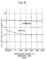
- FIGURE 16 (Sheet 10) shows a pair of curves which relate the electron beam spot size on the screen, along the major tube axis, at the 3D and 9D positions, as a function of the horizontal rate modulation voltage applied to the G4 electrode.
- FIGURE 17 (Sheet 11) shows a pair of curves which relate the electron beam spot size on the screen, along the minor tube axis, at the 6D and 12D positions, as a function of the vertical rate modulation voltage applied to the G4 electrode.
- FIGURE 1 shows a conventional rectangular color picture tube 10 having a glass envelope 11 comprising a rectangular faceplate panel 12 and a tubular neck 14 connected by a rectangular funnel 16.
- the panel 12 comprises a viewing faceplate 18 and a peripheral flange or sidewall 20, which is sealed to the funnel 16 by a frit seal 21.
- a mosaic three-color phosphor screen 22 is located on the interior surface of the faceplate 18.
- the screen preferably is a line screen, with the phosphor lines extending substantially perpendicular to the high frequency raster line scan of the tube (normal to the plane of the FIGURE 1).
- the screen could be a dot screen.
- a multi-apertured color selection electrode or shadow mask 24 is removably mounted, by conventional means, in predetermined spaced relation to the screen 22.
- An inline electron gun 26, shown schematically by dashed lines in FIGURE 1, is centrally mounted within the neck 14, to generate and direct three electron beams 28 along initially coplanar beam paths through the mask 24 and toward the screen 22.
- One type of electron gun that is conventional is a four-grid bipotential electron gun, such as that shown in FIGURE 2 herein and described in U.S. Pat. No. 4,620,133, issued to Morrell et al. on October 28, 1986.
- the tube of FIGURE 1 is designed to be used with an external magnetic deflection yoke, such as yoke 30, located in the region of the funnel-to-neck junction.
- yoke 30 When activated, the yoke 30 subjects the three beams 28 to magnetic fields which cause the beams to scan horizontally and vertically in a rectangular raster over the screen 22.
- the initial plane of deflection (at zero deflection) is shown by the line P-P in FIGURE 1 at about the middle of the yoke 30. Because of fringe fields, the zone of deflection of the tube extends axially from the yoke 30 into the region of the gun 26. For simplicity, the actual curvature of the deflected beam paths in the deflection zone is not shown in FIGURE 1.
- the yoke 30 provides an inhomogeneous magnetic field that has a strong pincushion-like vertical deflection magnetic field and a strong barrel-like horizontal deflection magnetic field, to converge the electron beams at the peripheral part of the screen 22.
- the beams are subject to distortions and defocusing.
- FIGURE 3 represents an electron beam spot for a single beam, which is circular at the center of the screen and undergoes various types of distortions at the periphery of the screen 22. As shown in FIGURE 3, the beam spot becomes horizontally elongated when deflected along the horizontal axis.
- the beam spot at the four corners of the screen comprises a combination of horizontally elongated portions and vertically elongated portions that form elliptically-shaped spots with halo-shaped elongations thereabout.
- the resolution is degraded as the electron beam is deflected, and the non-uniform focusing, which cannot be neglected, presents a problem which must be addressed.
- FIG. 4a herein shows an electron beam current density contour, at the center of the screen 22, for an electron beam produced by the beam-forming region and the main lens of the electron gun shown in FIGURE 2.
- the beam current of the electron gun is 4 milliamperes.
- the electron beam current density contour of FIGURE 4a comprises a relatively large center portion, having a substantially constant beam current of about 50% of the average beam current, and peripheral portions, where the beam current drops to about 5% of the average beam current and finally to about 1% of the average beam current.
- the beam is elliptically-shaped along the vertical axis, to reduce the overfocusing action of the yoke when the beam is deflected.
- FIGURE 4b shows the beam current density contour within the main lens, L2, that is between the G3 and G4 electrodes of FIGURE 2.
- the electron beam at this location is horizontally elongated; however, the 50% beam current density portion is contained within the small elliptical center section of the beam, which is circumscribed by the larger elliptical portions which represent the 5% and 1% beam current density contour of the electron beam deflected into the upper right hand corner of the screen. Same haloing occurs above and below the central portion of the beam.
- the beam spots produced on the screen by the conventional bipotential electron gun are unacceptable for large screen television sets and CAD/CAM applications.
- the details of an electron gun 40, according to the present invention, are shown in FIGURES 5 and 6.
- the gun 40 comprises three equally-spaced, coplanar cathodes 42 (one for each beam), a control grid 44 (G1), a screen grid 46 (G2), a third electrode 48 (G3), a fourth electrode 50 (G4), a fifth electrode 52 (G5), the G5 electrode including a G5′ portion 54 and a G5 ⁇ portion 55, and a sixth electrode 56 (G6).
- the electrodes are spaced in the order named from the cathodes and are attached to a pair of glass support rods (not shown).
- the cathodes 42, the G1 electrode 44, the G2 electrode 46 and a portion of the G3 electrode 48 facing the G2 electrode 46 comprise a beam-forming region of the electron gun 40.
- Another portion of the G3 electrode 48, the G4 electrode 50 and the G5 ⁇ portion 55 of the G5 electrode 52 comprise a first asymmetric lens.
- the G5′ portion 54 of the G5 electrode 52 and the G6 electrode 56 comprise a main focusing (or second asymmetric) lens.
- Each cathode 42 comprises a cathode sleeve 58 closed at its forward end by a cap 60 having an end coating 62 of an electron-emissive material thereon, as is known in the art.
- Each cathode 42 is indirectly heated by a heater coil (not shown) positioned within the sleeve 58.
- the G1 and G2 electrodes, 44 and 46 are two closely-spaced, substantially-flat plates each having three pairs of inline apertures 64 and 66, respectively, therethrough.
- the apertures 64 and 66 are centered with the cathode coatings 62, to initiate three equally-spaced coplanar electron beams 28 (as shown in FIGURE 1) directed towards the screen 22.
- the initial electron beam paths are substantially parallel, with the middle path coinciding with the central axis A-A of the electron gun.
- the G3 electrode 48 includes a substantially flat outer plate 68 having three inline apertures 70 therethrough, which are aligned with the apertures 66 and 64 in the G2 and G1 electrodes 46 and 44, respectively.
- the G3 electrode 48 also includes a pair of cup-shaped first and second portions 72 and 74, respectively, which are joined together at their open ends.
- the first portion 72 has three inline apertures 76 formed through the bottom of the cup, which are aligned with the apertures 70 in the plate 68.
- the second portion 74 of the G3 electrode has three apertures 78 formed through its bottom, which are aligned with the apertures 76 in the first portion 72. Extrusions 79 surround the apertures 78.
- the plate 68 with its inline apertures 70 may be formed as an integral part of the first portion 72.
- the novel G4 modulation electrode 50 comprises a substantially flat plate having three rotationally-asymmetrical inline apertures 80 formed therethrough, which are aligned with the apertures 78 in the G3 electrode.
- the shape of the apertures 80 is shown in FIGURE 7.
- the rotationally-asymmetrical apertures 80 are elongated in the horizontal direction, i.e., in the direction of the inline apertures.
- Each of the apertures 80 includes a substantially circular center portion comprising a primary opening 120 having a radius, r1 , of 0.079 inch (2.007 mm) and a pair of oppositely disposed arcuate portions 122 formed by secondary openings located on each side of the primary opening.
- the secondary openings partially overlie the primary opening 120, and each has a radius, r2 , of 0.020 inch (0.511 mm) and is located on the horizontal axis B-B a distance of 0.067 inch (2.302 mm) from the center of the opening 120, so that the overall horizontal dimension, H, of the aperture 80 is 0.174 inch (4.420 mm).
- the secondary openings 122 are blended smoothly into the primary openings 120.
- the maximum vertical dimension, V, of the aperture 80 is 0.158 inch (4.013 mm) and is equal to the diameter of the primary opening 120.
- the circular primary openings facilitate assembly of the electron gun components on cylindrical mount pins.
- the rotationally-asymmetrical apertures 80 provide a quadrupole focusing effect on the beams passing therethrough, which effect is enhanced by the application of application of a dynamic voltage thereto which varies with the deflection of the electron beams.
- the application of dynamic voltages to a relatively low voltage element of an electron gun is disclosed in the above-cited U.S. Pat. No. 4,319,163.
- the G5 ⁇ electrode portion 52 comprises a first deep-drawn, cup-shaped member having three apertures 82, surrounded by extrusions 83, formed in the bottom end thereof.
- the G5′ electrode portion 54 comprises a second deep-drawn, cup-shaped member having a recess 92 formed in the bottom end, with three inline apertures 94 formed in the bottom surface thereof. Extrusions 95 surround the apertures 94.
- the opposite open end of the G5′ electrode portion 54 is closed by a second plate portion 96 having three openings 98 formed therethrough, which are aligned and cooperate with the openings 90 in the first plate portion 88 in a manner described below.
- the G6 electrode 56 is a cup-shaped, deep-drawn member having a large opening 100 at one end, through which all three electron beams pass, and an open end, which is attached to and closed by a plate member 102 that has three apertures 104 therethrough which are aligned with the apertures 94 in the G5′ electrode portion 54. Extrusions 105 surround the apertures 104.
- the shape of the recess 92 in the G5′ electrode portion 54 is shown in FIGURE 8.
- the recess 92 has a uniform vertical width at each of the electron beam paths, with rounded ends. Such a shape has been referred to as the "racetrack" shape.
- the shape of the large opening 100 in the G6 electrode 56 is shown in FIGURE 9.
- the aperture 100 is vertically higher at the side electron beam paths than it is at the center beam path.
- Such a shape has been referred to as the "dogbone” or “barbell” shape.
- the first plate portion 88 of the G5 ⁇ electrode portion 52 faces the second plate portion 96 of the G5′ electrode portion 54.
- the openings 90 in the first plate portion 88 have extrusions, extending from the plate portion, that have been divided into two segments 106 and 108 for each opening.
- the openings 98 in the second plate portion 96 also have extrusions, extending from the plate portion 96, that have been divided into two segments 110 and 112 for each opening.
- the segments 106 and 108 are interleaved with the segments 110 and 112. These segments are used to create multipole (e.g., quadrupole) lenses in the paths of each electron beam when different potentials are applied to the G5 ⁇ and G5′ electrode portions 52 and 54, respectively.
- the electron gun 40 is electrically connected as shown in FIGURE 6.
- the cathode operates at about 150V
- the G1 electrode is at ground potential
- the G2 electrode operates within the range of about 300V to 1000V
- the G3 electrode and G5 ⁇ electrode portion are electrically interconnected and operate at about 7kV
- the G6 electrode operates at an anode potential of about 25kV.
- At least one dynamic voltage signal is applied to the G4 electrode and another dynamic voltage signal is applied to the G5′ electrode portion.
- the first lens, L1 (FIGURE 6) comprising the G1 electrode 44, the G2 electrode 46 and the adjacent portion of the G3 electrode 48, provides a symmetrically-shaped high quality electron beam rather than an asymmetrically-shaped electron beam into the second lens, L2.
- the beam current density contour of one of the beams of L1 is shown in FIGURE 11. It can be seen that the present beam-forming region does not introduce any appreciable asymmetry into the electron beam.
- the second lens, L2 comprising the G4 modulation electrode 50 and the adjacent portions of the G3 electrode 48 and the G5 electrode 52 (i.e., the G5 ⁇ electrode portion), constitutes an asymmetric lens which provides a horizontally-elongated electron beam which, within the third or main focus lens, L3, has the beam spot contour shown in FIGURE 12.
- the substantially oval shape of the electron beam is produced by the combination of the rotationally asymmetrical apertures 80 formed through the G4 electrode 50 and the dynamic voltage applied thereto.
- the main, or third, focus lens, L3, formed between the G5′ electrode portion 54 and the G6 electrode 56 also is a low aberration lens, which is optimized, as described below, for zero astigmatism at the center of the screen, with the main lens modulation electrode portion 54 and the focus electrode 52 at the same potential (about 7KV) and the G4 electrode 50 at the same potential (about 350 V) as the G2 electrode 46.
- the G4 modulation electrode 50 is effective for both horizontal rate modulation (15.75 KHz) along the major tube (inline) axis from the 3D to the 9D screen locations, and for the vertical rate modulation (60 Hz) along the minor tube axis (normal to the inline axis) from the 6D to the 12D screen locations.
- the G4 electrode is too close to the electron beam crossover position at high currents, it cannot totally compensate for deflection defocusing in the 2D and 10D tube corners (and also, by symmetry, in the 4D and 8D corners).
- the present invention utilizes dual modulation electrodes.
- the horizontal rate modulation is accomplished by superimposing a substantially parabolic voltage signal which increases with deflection angle, onto the focus supply voltage which is coupled to the G5′ electrode portion 54.
- Vertical rate modulation is achieved by applying a different parabolic voltage signal, which also increases with deflection angle, onto the low focus voltage applied to the G4 electrode 50.
- FIGURE 13 shows a first curve 124 that depicts the horizontal rate modulation voltage signal, with respect to the (screen center) focus voltage (7kV) that is required on the G5′ electrode portion 54, to focus the electron beams along the major tube axis from 3D to 9D.
- Curve 126 shows the higher horizontal rate modulation voltage necessary on the G5′ electrode portion 54, to focus the electron beams across the top (or bottom) of the screen from 2D to 10D (or 4D to 8D), when a suitable vertical rate modulation voltage signal is applied to the G4 electrode 50 for correcting the electron beam focus along the minor axis of the tube from 6D to 12D.
- the vertical rate modulation voltage signal curve 128 is shown in FIGURE 14.
- a disadvantage of the dual electrode dynamic modulation signal voltages suggested by the waveforms of FIGURES 13 and 14 is that the horizontal rate modulation voltage signal required to properly focus electron beams along the top of the screen and in the 2D and 10D corners (curve 126) is greater than that required for proper electron beam focus along the major axis from 3D to 9D (curve 124). That is, simultaneous focus along the major/minor axes and in the corner locations cannot be achieved completely with horizontal rate modulation of the G5′ main lens electrode portion 54 and vertical rate modulation of the G4 electrode 50. While adequate, the "simple" dual electrode dynamic modulation described above does not maximize the performance of the system.
- System performance is maximized by introducing a "compound" dual grid modulation which forces the total horizontal rate modulation voltages along the major axis (3D-9D) and in the corners (2D-10D) to be the same. This can be accomplished by applying an additional horizontal rate modulation voltage signal to the G4 modulation electrode 50 because, while the G4 electrode 50 is effective for horizontal rate modulation at the 3D and 9D screen locations, it has no effect on the 2D and 10D corners.
- the amplitude of the first horizontal rate modulation voltage signal applied to the G5′ electrode portion 54 can be increased to the values shown in curve 126, to focus the corners 2D and 10D while retaining the focus along the major axis at 3D and 9D.
- the second horizontal modulation rate voltage signal 130 is shown in FIGURE 15.
- FIGURES 16 and 17, respectively, show the effective of horizontal rate and vertical rate modulation voltage signals, applied to the G4 electrode 50, on beam spot size along the major axis at 3D-9D and the minor axis at 6D-12D.
- FIGURE 16 shows that, along the major axis, the electron beam spot size on the screen is horizontally elongated by about 1.6:1 at the desired operating point of about 300 volts below the G2 potential of 350V.
- FIGURE 17 shows that, along the minor axis at the 6D and 12D positions, the electron beam spot size on the screen is vertically elongated by about 1.7:1 at the desired operating point of about 300 volts above G2 potential.
- the modulation described above affects the vertical spot size without substantially effecting the horizontal spot size.
- the improved electron gun 40 comprises three lenses, the second and third of which can be separately modulated to correct astigmatism introduced into the electron gun from a self-converging yoke surrounding the tube in the junction of the funnel and the neck of the tube envelope.
- the third lens includes a G5′ electrode portion that can be modulated by a first voltage signal, at the horizontal scan rate, to provide a focusing correction of the electron beams on the screen along the direction of the major tube axis.
- a second voltage signal, at the vertical scan rate can be applied to the G4 electrode of the second lens to provide a focusing correction of the electron beams on the screen along the direction of the minor tube axis.
- the electron beams can be focused in the corners in addition to being optimized along the major and minor axes.
Landscapes
- Video Image Reproduction Devices For Color Tv Systems (AREA)
Claims (4)
- Farbanzeigesystem mit einer Kathodenstrahlröhre (10), die eine Hülle mit einer darin befindlichen Inline-Elektronenkanone (26) aufweist, um drei Inline-Elektronenstrahlen zu erzeugen und entlang von zunächst koplanaren Wegen auf einen Schirm (22) auf einem inneren Teil der Hülle zu richten, wobei die Kanone (26) eine Vielzahl von im Abstand voneinander angeordneten Elektroden (G1, G2, G3; G3, G4, G5, G5′, G6) enthält, die eine erste Linse (L1) und eine zweite Linse (12) und eine dritte Linse (L3) zur Fokussierung der Elektronenstrahlen vorsehen, wobei die erste Linse (L1) einen strahlformenden Bereich (G1, G2, G3) enthält, um im wesentlichen symmetrische Strahlen an die zweite Linse (L2) zu liefern, wobei die zweite Linse L2 eine erste Modulationselektrode (G4) der zweiten Linse, und das System ein selbstkonvergierendes Joch (30) enthält, das ein astigmatisches Feld für die Strahlen erzeugt;
wobei die zweite Linse (L2) Mittel enthält, um ein erstes Modulations-Spannungssignal (128) mit einer Vertikal-Rate der ersten Modulationselektrode 50 zuzuführen, sowie Mittel zur asymmetrischen Strahlfokussierung, um der dritten Linse (L3) asymmetrisch geformte Strahlen zuzuführen; und
wobei die dritte Linse (L3) Mittel enthält, um ein erstes Modulations-Spannungssignal (126) mit einer horizontalen Rate einer zweiten Modulationselektrode (54) zuzuführen, die elektrisch von der ersten Modulationselektrode (50) getrennt ist, wobei die ersten Modulationssignale mit der vertikalen und horizontalen Rate auf die Ablenkung der Elektronenstrahlen (28) bezogen sind;
wobei die zweite und dritte Linse im Betrieb getrennt durch Verwendung der elektrisch getrennten ersten (50) und zweiten (54) Modulationselektroden moduliert werden. - Farbanzeigesystem nach Anspruch 1, bei dem die erste Modulationselektrode (G4) zwischen zwei anderen Elektroden (G3, G5) der zweiten Linse angeordnet ist.
- Farbanzeigesystem nach Anspruch 1, bei dem die zweite Linse (L2) rotationsasymmetrische Strahlfokussierungsmittel enthält, um asymmetrisch geformte Strahlen an die dritte Linse zu liefern, wobei die dritte Linse eine Haupt-Fokussierungslinse mit geringer Aberration ist;
wobei die rotationssymmetrischen Strahlfokussierungsmittel für die zweite Linse (L2) eine erste Modulationselektrode (50) mit drei durch sie hindurch verlaufenden rotationsasymmetrischen Inline-Ausnehmungen (80) enthält, von denen jede länglich in der Inline-Richtung verläuft und einen im wesentlichen kreisförmigen mittleren Teil (120) sowie zwei einander gegenüberliegende gekrümmte Teile (122) enthält, die den Umfang des kreisförmigen mittleren Teils schneiden. - Farbanzeigesystem nach Anspruch 1, 2 oder 3, das ferner Mittel enthält, um der ersten Modulationselektrode (50) der zweiten Linse (L2) ein zweites Modulations-Spannungssignal (130) mit horizontaler Rate zuzuführen, wobei das zweite Modulations-Spannungssignal mit horizontaler Rate auch auf die Ablenkung der Elektronenstrahlen (28) bezogen ist.
Applications Claiming Priority (2)
| Application Number | Priority Date | Filing Date | Title |
|---|---|---|---|
| US07/263,454 US4877998A (en) | 1988-10-27 | 1988-10-27 | Color display system having an electron gun with dual electrode modulation |
| US263454 | 1988-10-27 |
Publications (3)
| Publication Number | Publication Date |
|---|---|
| EP0366245A2 EP0366245A2 (de) | 1990-05-02 |
| EP0366245A3 EP0366245A3 (en) | 1990-10-17 |
| EP0366245B1 true EP0366245B1 (de) | 1994-12-07 |
Family
ID=23001847
Family Applications (1)
| Application Number | Title | Priority Date | Filing Date |
|---|---|---|---|
| EP89309148A Expired - Lifetime EP0366245B1 (de) | 1988-10-27 | 1989-09-08 | Farbanzeigesystem und Röhre, versehen mit einer an zwei Elektroden modulierten Elektronenkanone |
Country Status (10)
| Country | Link |
|---|---|
| US (1) | US4877998A (de) |
| EP (1) | EP0366245B1 (de) |
| JP (1) | JPH0795429B2 (de) |
| KR (1) | KR0121798B1 (de) |
| CN (1) | CN1017204B (de) |
| CA (1) | CA1317033C (de) |
| DD (1) | DD288266A5 (de) |
| DE (1) | DE68919803T2 (de) |
| PL (1) | PL162108B1 (de) |
| RU (1) | RU2030808C1 (de) |
Cited By (1)
| Publication number | Priority date | Publication date | Assignee | Title |
|---|---|---|---|---|
| US6057013A (en) * | 1996-03-07 | 2000-05-02 | Chevron Chemical Company | Oxygen scavenging system including a by-product neutralizing material |
Families Citing this family (32)
| Publication number | Priority date | Publication date | Assignee | Title |
|---|---|---|---|---|
| US5262702A (en) * | 1989-03-23 | 1993-11-16 | Kabushiki Kaisha Toshiba | Color cathode-ray tube apparatus |
| US5036258A (en) * | 1989-08-11 | 1991-07-30 | Zenith Electronics Corporation | Color CRT system and process with dynamic quadrupole lens structure |
| JPH088078B2 (ja) * | 1989-10-16 | 1996-01-29 | 松下電子工業株式会社 | カラー受像管装置 |
| EP0427235B1 (de) * | 1989-11-09 | 1996-01-31 | Kabushiki Kaisha Toshiba | Farbkathodenstrahlröhre und ihr Steuerungsverfahren |
| KR970008564B1 (ko) * | 1989-11-21 | 1997-05-27 | 엘지전자 주식회사 | 칼라음극선관용 전자총 |
| JP3053827B2 (ja) * | 1990-02-08 | 2000-06-19 | 株式会社日立製作所 | 電子銃および陰極線管 |
| US5066887A (en) * | 1990-02-22 | 1991-11-19 | Rca Thomson Licensing Corp. | Color picture tube having an inline electron gun with an astigmatic prefocusing lens |
| US5202604A (en) * | 1990-05-08 | 1993-04-13 | Samsung Electron Devices Co., Ltd. | Electron gun for cathode ray tube |
| US4990832A (en) * | 1990-05-22 | 1991-02-05 | Rca Licensing Corporation | Color display system |
| JP3053845B2 (ja) * | 1990-06-07 | 2000-06-19 | 株式会社日立製作所 | 陰極線管 |
| GB9104649D0 (en) * | 1991-03-05 | 1991-04-17 | Secr Defence | Focusing means for cathode ray tubes |
| DE69209125T2 (de) * | 1991-04-17 | 1996-10-02 | Philips Electronics Nv | Bildwiedergabeanordnung und Elektronenstrahlröhre |
| FR2682809B1 (fr) * | 1991-10-21 | 1993-12-31 | Thomson Tubes Displays Sa | Tube a rayons cathodiques a canon a electrons ameliore. |
| JP3339059B2 (ja) * | 1991-11-14 | 2002-10-28 | ソニー株式会社 | 陰極線管 |
| FR2705164B1 (fr) * | 1993-05-10 | 1995-07-13 | Thomson Tubes & Displays | Tube image couleurs à canons à électrons en ligne avec lentilles astigmatiques. |
| JPH0721936A (ja) | 1993-06-30 | 1995-01-24 | Hitachi Ltd | 陰極線管 |
| JPH07134953A (ja) * | 1993-11-09 | 1995-05-23 | Hitachi Ltd | カラー受像管 |
| KR970001591B1 (ko) * | 1993-11-30 | 1997-02-11 | 오리온전기 주식회사 | 칼라 음극선관용 전자총 |
| JPH07161308A (ja) * | 1993-12-07 | 1995-06-23 | Hitachi Ltd | カラー陰極線管用電子銃 |
| KR950020923A (ko) * | 1993-12-07 | 1995-07-26 | 이헌조 | 컬러 브라운관용 전자총 |
| WO1995030999A2 (en) * | 1994-05-06 | 1995-11-16 | Philips Electronics N.V. | Display device and cathode ray tube |
| KR100192456B1 (ko) * | 1994-08-13 | 1999-06-15 | 구자홍 | 칼라수상관용 전자총구체 |
| KR100186540B1 (ko) | 1996-04-25 | 1999-03-20 | 구자홍 | 피디피의 전극 및 그 형성방법 |
| JP3726402B2 (ja) * | 1996-07-05 | 2005-12-14 | ソニー株式会社 | カラー陰極線管用インライン電子銃 |
| JP2000504474A (ja) * | 1996-11-04 | 2000-04-11 | フィリップス エレクトロニクス ネムローゼ フェンノートシャップ | インライン型電子銃を有するカラー陰極線管 |
| TW402732B (en) * | 1998-06-09 | 2000-08-21 | Koninkl Philips Electronics Nv | Cathode ray tube comprising an electron gun |
| FR2810488B1 (fr) * | 2000-06-16 | 2002-08-30 | St Microelectronics Sa | Correction de convergence d'un ecran ou projecteur a tube cathodique |
| KR100357172B1 (ko) * | 2000-12-23 | 2002-10-19 | 엘지전자주식회사 | 컬러 음극선관용 전자총 |
| KR100719533B1 (ko) * | 2001-05-04 | 2007-05-17 | 삼성에스디아이 주식회사 | 칼라 음극선관용 전자총 |
| KR20020085463A (ko) * | 2001-05-08 | 2002-11-16 | 삼성에스디아이 주식회사 | 빔 인덱스형 음극선관의 전자총 |
| CA2563517C (en) * | 2004-05-03 | 2012-09-11 | The University Of British Columbia | Method for efficient computation of image frames for dual modulation display systems using key frames |
| CN109211101B (zh) * | 2018-10-11 | 2023-09-22 | 中国科学院电工研究所 | 一种电子束对中检测管以及电子束对中检测装置 |
Family Cites Families (12)
| Publication number | Priority date | Publication date | Assignee | Title |
|---|---|---|---|---|
| JPS5715463B2 (de) * | 1973-11-13 | 1982-03-30 | ||
| US3984723A (en) * | 1974-10-04 | 1976-10-05 | Rca Corporation | Display system utilizing beam shape correction |
| US3952224A (en) * | 1974-10-04 | 1976-04-20 | Rca Corporation | In-line electron guns having consecutive grids with aligned vertical, substantially elliptical apertures |
| US4234814A (en) * | 1978-09-25 | 1980-11-18 | Rca Corporation | Electron gun with astigmatic flare-reducing beam forming region |
| US4319163A (en) * | 1980-06-30 | 1982-03-09 | Rca Corporation | Electron gun with deflection-synchronized astigmatic screen grid means |
| US4620133A (en) * | 1982-01-29 | 1986-10-28 | Rca Corporation | Color image display systems |
| JPS6199249A (ja) * | 1984-10-18 | 1986-05-17 | Matsushita Electronics Corp | 受像管装置 |
| NL8600117A (nl) * | 1986-01-21 | 1987-08-17 | Philips Nv | Kleurenbeeldbuis met verminderde deflectie defocussering. |
| US4731563A (en) * | 1986-09-29 | 1988-03-15 | Rca Corporation | Color display system |
| JP2569027B2 (ja) * | 1986-12-05 | 1997-01-08 | 株式会社日立製作所 | カラ−受像管用電子銃 |
| US4764704A (en) * | 1987-01-14 | 1988-08-16 | Rca Licensing Corporation | Color cathode-ray tube having a three-lens electron gun |
| DE3854506T2 (de) * | 1987-01-14 | 1996-04-04 | Rca Thomson Licensing Corp | Farbbildröhre mit einer Drei-Linsen-Elektronenkanone. |
-
1988
- 1988-10-27 US US07/263,454 patent/US4877998A/en not_active Expired - Lifetime
-
1989
- 1989-09-08 EP EP89309148A patent/EP0366245B1/de not_active Expired - Lifetime
- 1989-09-08 DD DD89332483A patent/DD288266A5/de not_active IP Right Cessation
- 1989-09-08 DE DE68919803T patent/DE68919803T2/de not_active Expired - Lifetime
- 1989-09-14 CA CA000611427A patent/CA1317033C/en not_active Expired - Fee Related
- 1989-09-22 JP JP1247862A patent/JPH0795429B2/ja not_active Expired - Lifetime
- 1989-09-22 PL PL89281553A patent/PL162108B1/pl unknown
- 1989-10-03 RU SU4614989/21A patent/RU2030808C1/ru not_active IP Right Cessation
- 1989-10-10 CN CN89107897A patent/CN1017204B/zh not_active Expired
- 1989-10-24 KR KR1019890015364A patent/KR0121798B1/ko not_active Expired - Fee Related
Cited By (1)
| Publication number | Priority date | Publication date | Assignee | Title |
|---|---|---|---|---|
| US6057013A (en) * | 1996-03-07 | 2000-05-02 | Chevron Chemical Company | Oxygen scavenging system including a by-product neutralizing material |
Also Published As
| Publication number | Publication date |
|---|---|
| US4877998A (en) | 1989-10-31 |
| DE68919803T2 (de) | 1995-06-08 |
| DD288266A5 (de) | 1991-03-21 |
| PL162108B1 (pl) | 1993-08-31 |
| EP0366245A2 (de) | 1990-05-02 |
| CN1042270A (zh) | 1990-05-16 |
| JPH02127887A (ja) | 1990-05-16 |
| RU2030808C1 (ru) | 1995-03-10 |
| CN1017204B (zh) | 1992-06-24 |
| CA1317033C (en) | 1993-04-27 |
| DE68919803D1 (de) | 1995-01-19 |
| KR0121798B1 (ko) | 1997-11-15 |
| JPH0795429B2 (ja) | 1995-10-11 |
| EP0366245A3 (en) | 1990-10-17 |
| KR900007037A (ko) | 1990-05-09 |
Similar Documents
| Publication | Publication Date | Title |
|---|---|---|
| EP0366245B1 (de) | Farbanzeigesystem und Röhre, versehen mit einer an zwei Elektroden modulierten Elektronenkanone | |
| EP0485515B1 (de) | Verfahren und vorrichtung zur kontrolle der dynamischen konvergenz mehrerer elektronenstrahlen in einer farbkathodenstrahlröhre | |
| CA2036857C (en) | Color picture tube having an inline electron gun with an astigmatic prefocusing lens | |
| US4764704A (en) | Color cathode-ray tube having a three-lens electron gun | |
| US5055749A (en) | Self-convergent electron gun system | |
| EP0265683B1 (de) | Farbanzeigevorrichtung und Kathodenstrahlröhre | |
| EP0235975B1 (de) | Kathodenstrahlröhre und Farbanzeigevorrichtung | |
| EP0300704B1 (de) | Farbbildröhre mit Inline-Elektronenkanone und einer Einzellinse | |
| US6172450B1 (en) | Election gun having specific focusing structure | |
| EP0300705B1 (de) | Farbbildröhre mit Inline-Elektronenkanone und einer Einzellinse | |
| EP0178857B1 (de) | Elektronenkanone | |
| JPH0714527A (ja) | 3つの非点収差レンズを設けたインライン電子銃を有するカラー画像管 | |
| EP0452789B1 (de) | Farbbildröhre mit "inline" Elektronenkanone mit Fokusjustierung | |
| EP0275191B1 (de) | Farbbildröhre mit einer Drei-Linsen-Elektronenkanone | |
| US6597096B1 (en) | Color cathode-ray tube electron gun | |
| GB2144903A (en) | Cathode-ray tube with electron gun having an astigmatic beam forming region | |
| HK1010422A (en) | Method and apparatus for controlling dynamic convergence of a plurality of electron beams of a color cathode ray tube | |
| JPH03283337A (ja) | カラー受像管装置 |
Legal Events
| Date | Code | Title | Description |
|---|---|---|---|
| PUAI | Public reference made under article 153(3) epc to a published international application that has entered the european phase |
Free format text: ORIGINAL CODE: 0009012 |
|
| AK | Designated contracting states |
Kind code of ref document: A2 Designated state(s): DE FR GB IT |
|
| PUAL | Search report despatched |
Free format text: ORIGINAL CODE: 0009013 |
|
| AK | Designated contracting states |
Kind code of ref document: A3 Designated state(s): DE FR GB IT |
|
| 17P | Request for examination filed |
Effective date: 19901217 |
|
| RAP1 | Party data changed (applicant data changed or rights of an application transferred) |
Owner name: RCA THOMSON LICENSING CORPORATION |
|
| 17Q | First examination report despatched |
Effective date: 19930521 |
|
| GRAA | (expected) grant |
Free format text: ORIGINAL CODE: 0009210 |
|
| AK | Designated contracting states |
Kind code of ref document: B1 Designated state(s): DE FR GB IT |
|
| ITF | It: translation for a ep patent filed | ||
| REF | Corresponds to: |
Ref document number: 68919803 Country of ref document: DE Date of ref document: 19950119 |
|
| ET | Fr: translation filed | ||
| PLBE | No opposition filed within time limit |
Free format text: ORIGINAL CODE: 0009261 |
|
| STAA | Information on the status of an ep patent application or granted ep patent |
Free format text: STATUS: NO OPPOSITION FILED WITHIN TIME LIMIT |
|
| 26N | No opposition filed | ||
| REG | Reference to a national code |
Ref country code: GB Ref legal event code: IF02 |
|
| REG | Reference to a national code |
Ref country code: FR Ref legal event code: D6 |
|
| REG | Reference to a national code |
Ref country code: GB Ref legal event code: 746 Effective date: 20030110 |
|
| PGFP | Annual fee paid to national office [announced via postgrant information from national office to epo] |
Ref country code: IT Payment date: 20080926 Year of fee payment: 20 |
|
| PGFP | Annual fee paid to national office [announced via postgrant information from national office to epo] |
Ref country code: GB Payment date: 20080828 Year of fee payment: 20 |
|
| PGFP | Annual fee paid to national office [announced via postgrant information from national office to epo] |
Ref country code: DE Payment date: 20080924 Year of fee payment: 20 |
|
| PGFP | Annual fee paid to national office [announced via postgrant information from national office to epo] |
Ref country code: FR Payment date: 20080923 Year of fee payment: 20 |
|
| REG | Reference to a national code |
Ref country code: GB Ref legal event code: PE20 Expiry date: 20090907 |
|
| PG25 | Lapsed in a contracting state [announced via postgrant information from national office to epo] |
Ref country code: GB Free format text: LAPSE BECAUSE OF EXPIRATION OF PROTECTION Effective date: 20090907 |