EP0366174B1 - Maschine zum Aufsammeln von auf dem Boden liegenden Früchten oder dergleichen - Google Patents
Maschine zum Aufsammeln von auf dem Boden liegenden Früchten oder dergleichen Download PDFInfo
- Publication number
- EP0366174B1 EP0366174B1 EP89202548A EP89202548A EP0366174B1 EP 0366174 B1 EP0366174 B1 EP 0366174B1 EP 89202548 A EP89202548 A EP 89202548A EP 89202548 A EP89202548 A EP 89202548A EP 0366174 B1 EP0366174 B1 EP 0366174B1
- Authority
- EP
- European Patent Office
- Prior art keywords
- devices
- machine according
- projection
- designed
- band
- Prior art date
- Legal status (The legal status is an assumption and is not a legal conclusion. Google has not performed a legal analysis and makes no representation as to the accuracy of the status listed.)
- Expired - Lifetime
Links
Images


Classifications
-
- A—HUMAN NECESSITIES
- A01—AGRICULTURE; FORESTRY; ANIMAL HUSBANDRY; HUNTING; TRAPPING; FISHING
- A01D—HARVESTING; MOWING
- A01D51/00—Apparatus for gathering together crops spread on the soil, e.g. apples, beets, nuts, potatoes, cotton, cane sugar
- A01D51/002—Apparatus for gathering together crops spread on the soil, e.g. apples, beets, nuts, potatoes, cotton, cane sugar for apples or nuts
-
- Y—GENERAL TAGGING OF NEW TECHNOLOGICAL DEVELOPMENTS; GENERAL TAGGING OF CROSS-SECTIONAL TECHNOLOGIES SPANNING OVER SEVERAL SECTIONS OF THE IPC; TECHNICAL SUBJECTS COVERED BY FORMER USPC CROSS-REFERENCE ART COLLECTIONS [XRACs] AND DIGESTS
- Y10—TECHNICAL SUBJECTS COVERED BY FORMER USPC
- Y10S—TECHNICAL SUBJECTS COVERED BY FORMER USPC CROSS-REFERENCE ART COLLECTIONS [XRACs] AND DIGESTS
- Y10S56/00—Harvesters
- Y10S56/21—Raking and windrowing
Definitions
- the invention relates to a machine for harvesting fruit or the like distributed over the ground. It applies in particular to harvest fruits such as plums, nuts, hazelnuts, apples, etc. fallen on the ground, but can extend to the collection of all similar objects of rounded shapes, dispersed over a surface. To simplify the description, the term “fruit” will be used subsequently which must therefore be taken in a more general sense: "fruit or the like”.
- a first type of mechanical picking machine is known, which is intended for the harvesting of hard fruits such as nuts. These machines are equipped with metal combs which rake the surface, which makes them totally unsuitable for harvesting more fragile fruits such as plums which would suffer serious damage during this mechanical raking.
- Another type of machine uses a powerful blast of air directed towards the ground to ensure pneumatic transfer of the fruit to a conveyor.
- this type of machine requires significant pneumatic power; for fragile fruits, they cause wounds on dry soil, while in wet soil, they are the seat of stuffing making their passage problematic.
- these machines tend to accentuate the irregularities of the ground by digging the bowls and parts already hollow.
- a machine has also been proposed comprising an endless screw which turns in contact with the ground in an oblique position in order to collect the fruits and bring them to an endless belt elevator (US Pat. No. 4,706,447).
- an endless belt elevator US Pat. No. 4,706,447
- part of the fruit is necessarily crushed by the endless belt and the wheels; in addition, the worm also causes risks of crushing at its propeller as well as risks of deterioration of the fruits during the transverse movement of the latter.
- the present invention proposes to provide a new harvesting machine which makes it possible to collect even fragile fruits without damaging them. It aims to provide a machine to ensure a total harvest of fruit in both wet and dry soil.
- the machine according to the present invention is characterized in that it comprises a first line of projection members, called front members, distributed over a predetermined width with an overlap of their edges at with the exception of two passages arranged to cause the formation of two swaths, and a second line comprising two projection members, called rear members, located at the rear of each of the passages, the receiving belt being located between said rear members of so as to cooperate with the edges of said members and to be concealed behind members of the first line, the frame being carried by displacement means such as wheels, themselves positioned so as to be concealed at the rear front projection devices.
- each projection member is constituted by a brush rotating around an axis parallel to the ground with a direction of rotation such that the front part of the brush moves from bottom to top.
- Said brush is advantageously arranged in an oblique position relative to its direction of movement so as to ensure the accumulation of fruit towards the edge of the brush which is located the rearmost (with respect to this direction of movement).
- the fruits are driven back in front of rotating members which cause them to roll on the ground until forming a linear accumulation (swath) which is entrained by the receiving surface.
- a linear accumulation swath
- Such a machine no longer uses a pneumatic jet and is therefore freed from all the related faults; moreover, the repression of each fruit by simple contact with a rotating member such as a brush can be carried out without injuring it, unlike the combing process by combs which damages fragile fruits or the process of ejection between two brushes who crushes them.
- the front projection members perform a first job of accumulating the fruit in two swaths, which then allows the two rear projection members to push all of these onto the receiving surface.
- This receiving surface and the wheels of the machine are arranged in alignment with and behind the front projection members so as to move over already swept ground, without the risk of crushing fruit.
- this arrangement in several independent projection members makes it possible to cover a wide strip of land (in particular the half-width between two lines of trees), while providing projection members of reduced length ensuring correct positioning of each member above the ground at a distance less than the diameter of a fruit, despite possible irregularities in the terrain.
- the receiving surface on which the swaths are collected is constituted by an endless belt having an active strand extending on the ground, parallel to the direction of movement, at the edge of one or more projection members; this carpet is animated by a scrolling movement causing it to roll without sliding on the ground with a direction of scrolling opposite to the direction of movement of the projection members.
- the fruits which roll on the ground along the projection members pass in a natural and smooth manner on the mat arriving near the edge of this member, since the active strand of said mat does not undergo any sliding relative to the ground and appears therefore stopped in relation to it (in a way constituting an extension of the ground in perfect continuity with it).
- the carpet closes on itself by an ascending strand, an upper return strand and a descending strand.
- the fruits entrained by transverse buckets along the ascending strand are then poured in the upper part onto conveyor means which transport them to the container.
- each projection member is advantageously constituted by a brush formed of bristles fixed on a horizontal axis associated with a hydraulic drive motor.
- each brush and its hydraulic motor are carried by a support articulated on the frame in order to be movable vertically and horizontally; this support is provided with a support pad on the ground which adjusts the height and allows the concerned brush to follow the possible irregularities of the ground at an appropriate height to push back all the fruits and to avoid a direct contact with the ground .
- the receiving belt comprises a chassis carried by a hydraulic lifting device adapted to allow it to be moved vertically; this chassis is secured to said lifting device by a double articulation around a longitudinal axis and around a transverse axis so as to be able to pivot transversely and from front to back.
- This double articulation gives the carpet, the active strand of which rests on the ground, a double freedom of movement allowing it to marry the irregularities of the ground and to collect satisfactorily the fruits repressed by the brushes, even on very irregular ground.
- the agricultural machine according to the invention can be associated with a tractor or, on the contrary, be autonomous and have its own engine and four-wheel drive and steering.
- the fruit storage container is located at the rear and the conveying means advantageously comprise a receiving hopper arranged in the angle formed by the ascending strand and the upper strand of the conveyor belt so as to collect the fruits spilled at the change of direction, a short transverse conveyor arranged to receive the fruits collected in said hopper and to convey them transversely, a longitudinal conveyor arranged to receive the fruits at the end of the transverse conveyor and for transport to the rear container, and drive means of said transverse conveyor and longitudinal conveyor.
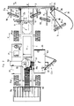
- the agricultural machine shown by way of example in the figures is intended for harvesting fallen fruit, in particular fragile fruits such as plums, in aligned tree plantations. It is sized to allow the fruit distributed between two lines of trees to be harvested in two passes, as symbolized in L1 and L2 in the diagram in Figure 11.
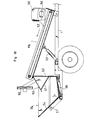
- This machine comprises a frame 1 of the tractor frame type that is equipped with various conventional equipment to make it self-propelled and self Thermal motor M, cockpit P, four-wheel drive and R AV Principals and R AR, hydraulic and central its reservoir H, driven by the engine ...
- this frame On this frame are mounted several specific assemblies of the invention which can be seen in the figures of assemblies 1 and 2, and which are described in detail below: essentially an assembly front with five brushes E A intended to carry out a first work of accumulation in two swaths, a couple of rear brushes C B taking up these two swaths and cooperating with a belt receiving assembly E R , means of conveying M C of the fruits collected by all of reception and a rear container Be.
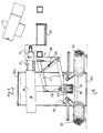
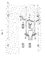
- the front assembly E A which is shown in detail in FIGS. 3, 4, 5 and 6 is carried by a frame 2 which is fixed to the frame 1 and comprises, at the front of the side members 2a, a transverse member 3.
- This frame carries a horizontal lower rod 4 around which are articulated five brush supports: two left lateral supports 5, 6 carrying two lateral brushes 10 and 11, two central supports 7 and 8 carrying two central brushes 12 and 13, and a lateral support right 9 carrying a retractable side brush 14.
- Each brush support is articulated on the rod 4 by a sleeve such as 15 so as to be movable vertically.
- the supports 5, 6, 7 and 8 are similar and shown in detail in FIGS. 4 and 5.
- Each comprises, on the one hand, a support bar 16 of approximately longitudinal direction at the end of which is fixed, by the through a joint 23, the brush and its hydraulic motor, on the other hand, a stick 17 secured to the support bar 16 and carrying a pad 18 of adjustable height located at the rear of the brush concerned.
- Each brush is constituted by a multitude of radial bristles, in particular of anti-wear synthetic material, giving them a semi-rigid character, these bristles being fixed on an axis 19.
- This axis is coupled at one end to a hydraulic motor 20 and carried at its opposite end by a yoke 21 which is extended by a bar 22 which closes on the casing of the hydraulic motor.
- the bar 22 carries the articulation 23 which allows the brush / motor assembly to pivot around the axis of the support bar 16 so as to be movable above the ground in a transverse plane.
- each brush in the working position is substantially horizontal above the ground at a constant height adjusted by the pad 18; this height can be adjusted to be of the order of 1/3 D to 1/2 D, where D is the diameter of the fruits to be harvested (for example, height of about 1.5 cm for plums with a diameter of l '' order 3 to 4 cm).
- the brush follows the ground and any irregularities at constant height by pivoting around the transverse rod 4 under the action of the shoe 18. In addition, in the event of a local irregularity not detected by the shoe, it can be erased by the play of the joint 23.
- the machine is equipped with hydraulic lifting means making it possible to vertically move all of the front brush supports between the working position close to the ground and a raised position (road position).
- hydraulic lifting means are in the example constituted by a lifting bar 24, articulated at the ends of the rod 4 and on which are coupled two hydraulic cylinders such as 25 (FIG. 3), making it possible to fold this bar 24 backwards : in this movement, said lifting bar comes into contact with the support bars 16 and lifts them.
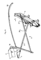
- the retractable brush 14 shown in FIG. 6 is supported by similar means with the exception of the following characteristics which make it retractable in the presence of a tree trunk.
- a curved bar 26 forming a feeler.
- it is associated with an additional link 28 in order to actuate it in an erasure movement.
- This link carries at its rear end the support pad of the brush and the probe 26 / link 28 assembly is articulated on the bar 3 by a vertical pivot 29 which gives it the freedom to pivot transversely when the probe 26 comes into contact. of a trunk.
- the brush support bar 27 carries the brush 14 by means of an additional articulation 30 around a vertical axis in order to allow the pivoting of said brush.
- a chain 31 retains the assembly during lifts to the road position.
- the two lateral brushes 10 and 11 are arranged with an obliqueness ⁇ with respect to the longitudinal direction which is the same direction for these two brushes and which is turned towards a longitudinal line X. These two brushes overlap at their contiguous edges.
- the two central brushes 12 and 13 are arranged with obliques opposite to each other, the obliquity of the brush 12 being turned towards the line X and the obliqueness of the brush 13 towards a line Y located on the other side. These two brushes overlap at their contiguous edges and are, on the contrary, separated from the neighboring brushes (respectively brush 11 and brush 14) to preserve two passages along the lines X and Y.
- the retractable side brush 14 has an oblique orientation towards the line Y.
- the oblique angle ⁇ of these various brushes is in absolute value substantially the same, between 50 ° and 80 °, and in particular of the order of 70 ° for these front brushes.
- the hydraulic motors of the brushes are powered by the hydraulic unit H of the machine and adapted to be able to drive the brushes in rotation in a speed range between 200 and 400 revolutions / minute; the direction of rotation is such that the bristles at the front have an upward movement (arrow r drawn in Figure 4).
- the front brushes 10-14 push the fruit across the width of the machine and make two swaths along the lines X and Y.
- the repression is generated by the impulses given by the hairs on each fruit during their rotation, impulses which cause the fruits to roll on the ground to accumulate along the only two passages X and Y existing across the width of the machine.
- the rear elements of the machine which come into contact with the ground are of course positioned outside these accumulation lines.
- the two left wheels are located at the rear of the side brushes 10 and 11 in order to be hidden by them, while the right wheels and the carpet are positioned behind the central brushes 12 and 13 and masked. by these.
- the retraction of the side brush 14 is carried out in the direction of the arrow -e- drawn in the figures (tendency to decrease the angle ⁇ ), so that the fruits are always pushed back towards the line Y .
- the machine comprises, at the rear of the assembly described above, two rear brushes 32 and 33 which cooperate with a receiving mat 34.
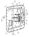
- These means are shown in detail in Figures 7, 8 and 9, respectively in simplified top view, in cross section and in longitudinal section.
- Each rear brush 32 or 33 is identical to the front brushes, driven in the same way by a hydraulic motor and provided with a support pad. These rear brushes are carried on either side of the receiving belt 34 by the chassis of the latter with reverse obliquities so that the fruits are pushed back towards the carpet.
- the obliquity angle ⁇ of these brushes relative to the direction of movement is the same in absolute value and is between 35 ° and 65 °, and in particular of the order of 55 °.
- These rear brushes 32 and 33 are arranged along lines X and Y so as to repress all of the fruit accumulated by the front brushes along these two lines.
- the receiving belt has a frame 35 consisting of two uprights and a spar, connecting four transverse axes which carry eight guide pulleys and driving the belt such as 36. These pulleys cooperate with lateral ribs between which stretches the carpet.
- This has transverse fruit retention strips such as 37 which form a plurality of cups.
- the bottom of these buckets is perforated by lights of dimensions adapted to allow the passage of the earth and foreign bodies, while retaining the fruits.
- the belt guided by the pulleys 36 is formed by four strands: a lower active strand 34i which cooperates with the brushes 32 and 33, an ascending strand 34a which raises the fruit towards a receiving hopper 38, an upper return strand 34s and a descending strand 34d.
- One of the shafts which carry two pulleys is driven in rotation by a hydraulic motor (not shown) adapted to drive it in the direction of the arrows f shown in FIG. 9, such that the active strand 34i has an opposite direction of travel.
- a hydraulic motor not shown
- the relative speed of movement of the mat with respect to the frame being equal in absolute value to the speed of movement of the machine so that the active strand 34i which is called upon to rest on the ground in the working position rolls without sliding on it.
- Two tensioning rollers such as 63 are articulated on the shaft of the front lower pulleys, in order to apply the belt to the ground in the area where the fruits are loaded on it; these tension rollers are elastically stressed by elastic tensioners or springs such as 64.
- the brushes 32 and 33 are carried by the chassis 35 of the carpet by means of a crosspiece 46 so that when the active bristle rests on the ground, their bristles pass flush with the ground (1.5 to 2 cm like the front brushes for plums).
- the rear edge of these brushes overlaps the side edges of the carpet as shown in Figure 7, so as to guide the fruit onto it.
- the transverse strips 37 of the mat are advantageously notched at the edge in order to allow the brushes to rotate freely without excessive wear.
- each flap 39 extends between the front part of the active strand and the front edge of the corresponding brush (FIG. 7).
- a flexible guiding flap 40 can also be provided at the rear of each brush to avoid lateral overflowing of the fruit, while the rear pulleys have full flanges for the same purpose.
- the receiving hopper 38 is fixed on an extension of the chassis 35 and contains a short transverse conveyor 41 for the transfer of the spilled fruit therein.
- the entrance to this hopper is arranged to extend as close as possible to the transverse strips 37 at the level of the change of direction, so as to collect all of the spilled fruit.
- the chassis 35 of the belt is carried by a hydraulic lifting device by means of a double articulation as shown in Figures 8 and 9 respectively in cross section and longitudinal section.
- the frame member 35 is first articulated around a transverse axis 42 which is carried by a yoke 43; this yoke 43 is in turn articulated around a longitudinal axis 44 which is carried by a beam 45.
- the latter is supported at its ends by two deformable parallelograms such as 47 which are articulated on two uprights such as 48 welded to the frame 1 of the machine.
- Two synchronous jacks such as 49 allow the longitudinal beam 45 to be moved vertically in order to arrange the receiving belt either in its working position with its active strand on the ground, or in a raised position (road position).
- a compensating spring 50 balances part of the weight of the carpet and reduces the force of support of the carpet on the ground.
- the double longitudinal (axis 44) and transverse (axis 42) articulation by which the chassis of the carpet is suspended under the spar 45 gives the carpet the ability to pivot transversely and from front to rear, and allows it to perfectly fit the ground .
- the transverse conveyor 41 is driven by a hydraulic motor 51 and pours the fruit onto the side of the belt on a longitudinal conveyor 52 which is in particular shown in FIG. 10.
- This conveyor 52 is driven by a hydraulic motor (not visible ); it is articulated on the frame 1 and carried by a jack 53 which makes it possible to arrange it either in a working position with its rear end situated above a container 54 (FIG. 10), or in a raised position in order to release the volume above said container for emptying thereof.
- suction means 55 are arranged, of the conventional type, which suck up foreign bodies and reject them via a sheath 56 on the side of the machine.
- the rear container 54 is articulated at the rear of the chassis by pins 57 and a jack 58 makes it possible to tilt it to empty the crop.
- This container comprises a vibrating grid 59 which is located under the rear end of the longitudinal conveyor 52 when the latter is in its working position.
- This grid is made up of bars spaced so as to retain the fruit and let the earth pass. In the example, it is made to vibrate thanks to a fan 60 which overcomes it and whose rotation has been unbalanced by reducing the weight of a blade (or by removing one of them).
- the container comprises means for evacuating the earth, constituted in the example by a hopper 61 and an opening 62.
- the diagram in Figure 11 shows the machine being harvested. It progresses in the direction -d- near a line of trees L1 and covers a width slightly greater than half the width between two lines of trees.
- the five front brushes 10-14 roll the fruits on the ground and push them back along the two lines X and Y forming two swaths which are taken up by the rear brushes 32 and 33.
- These direct the fruit onto the carpet 34, the active strand of which is placed on the ground with zero relative speed with respect thereto.
- the fruits are then conveyed to the rear container, via the conveyor belt, the transverse conveyor and the longitudinal conveyor. They are freed from the earth and foreign bodies at three levels: firstly, in the openwork cups of the carpet, then by the action of the suction 55, finally arriving on the vibrating grid 59.
- the machine according to the invention makes it possible to achieve a total harvest without damaging even fragile fruits.
Landscapes
- Life Sciences & Earth Sciences (AREA)
- Environmental Sciences (AREA)
- Harvesting Machines For Specific Crops (AREA)
Claims (17)
- Landwirtschaftliche Maschine zum Ernten von Früchten oder ähnlichen auf dem Boden liegenden Produkten, umfassend :- einen Rahmen (1), der so beschaffen ist, daß er sich in Richtung (d) verlagern läßt,- mindestens eine sich drehende Schleudervorrichtung (10-14, 32, 33) länglicher Form, die so an dem Rahmen angebracht ist, daß sie sich in Bodennähe und zwar schräg zu der Verlagerungsrichtung (d) befindet,- Mittel (20) zu drehendem Antrieb jeder Schleudervorrichtung, die so beschaffen sind, daß sie deren Umfang eine Bewegung (r) vermitteln, die Vorwärtsschleudern der Früchte bedingt,- ein an dem Rahmen angebrachtes Aufnahmeband (34) mit einem aktiven Trum (34i) an der Seite des Hinterrands von einer Schleudervorrichtung oder Schleudervorrichtungen, so daß es sich unterhalb der besagten Vorrichtungen und jenseits von diesen erstreckt,- Mittel zum Antrieb des Aufnahmebandes, die so beschaffen sind, daß sie dessen aktivem Trum (34i) eine Umlaufrichtung (f) vermitteln, die der Verlagerungsrichtung des Rahmens entgegengesetzt ist,- und Mittel (41, 52) zum Fördern der Früchte von dem Aufnahmeband zu einem Behälter (54),
wobei die besagte Maschine dadurch gekennzeichnet ist, daß sie eine erste Reihe von Schleudervorrichtungen, die sogenannten vorderen Vorrichtungen (10-14), umfaßt, die so über eine bestimmte Breite verteilt sind, daß deren Ränder mit Ausnahme von zwei zwecks Bildung von zwei Schwaden vorgesehenen Bahnen (X, Y) überlappen, sowie eine zweite Reihe mit zwei Schleudervorrichtungen, den sogenannten hinteren Vorrichtungen (32, 33), die sich am hinteren Ende jeder der besagten Bahnen befinden, während Aufnahmeband (34) zwischen den besagten hinteren Vorrichtungen angeordnet ist, so daß es mit den Rändern der besagten Vorrichtungen zusammenarbeitet und hinter den Vorrichtungen der ersten Reihe (12, 13) abgeschirmt ist, und Rahmen (1) durch Verlagerungsmittel wie Räder getragen wird, wobei die besagten Räder so angeordnet sind, daß sie hinter den vorderen Schleudervorrichtungen (10-13) abgeschirmt sind. - Maschine nach Anspruch 1, dadurch gekennzeichnet, daß jedes Schleuderorgan (10-14, 32, 33) aus einer Bürste besteht, die durch an einer zum Boden parallelen Spindel (19) angebrachte Borsten gebildet ist, wobei die besagte Spindel mit einem hydraulischen Antriebsmotor (20) gekoppelt ist.
- Maschine nach Anspruch 2, bei der jede Bürste und deren Hydraulikmotor an einer an einem Rahmen gelenkig angebrachten Stütze (7, 16) so angeordnet sind, daß sie sich in senkrechter und waagerechter Richtung verlagern lassen, wobei die besagte Stütze mit einem Fuß (18) versehen ist, der auf dem Boden aufgesetzt werden kann, um deren Höhe einzustellen.
- Maschine nach Anspruch 3, umfassend hydraulische Hebemittel (24, 25), die so beschaffen sind, daß sie senkrechte Verlagerung der Bürstenstützen gestatten.
- Maschine nach einem der Ansprüche 2, 3 oder 4, dadurch gekennzeichnet, daß jeder hydraulische Bürstenmotor (20) so beschaffen ist, daß er drehenden Antrieb innerhalb einer Drehzahlspanne zwischen 200 und 400 Umdrehungen/Minute gewährleisten kann.
- Machine nach einem der Ansprüche 2, 3, 4 oder 5, bei der jede Bürste (10-14, 32, 33) so angeordnet ist, daß ihr Winkel (α, β) im Verhältnis zu der Längsverlagerungsrichtung zwischen 35° und 80° beträgt.
- Maschine nach einem der Ansprüche 1 bis 6, dadurch gekennzeichnet, daß sie mindestens vier vordere Schleudervorrichtungen umfaßt,. und zwar zwei mittlere Vorrichtungen (12, 13), die so angeordnet sind, daß ihre anschließenden Ränder einander überlappen, wobei die besagten Vorrichtungen entgegengesetzte Neigungen in Richtung der beiden Längslinien (X) bzw. (Y) zu beiden Seiten der besagten Vorrichtungen aufweisen,. mindestens eine seitliche Vorrichtung (10, 11), die von den mittleren Vorrichtungen entfernt ist, so daß eine der besagten Bahnen entsteht, wobei die besagte seitliche Vorrichtung in Richtung einer der Längslinien (X) geneigt ist,. und an der anderen Seite mindestens eine seitliche Vorrichtung (14), die von den mittleren Vorrichtungen entfernt ist, so daß die andere Bahn gebildet wird, wobei die besagte Vorrichtung in Richtung der anderen Längslinie (Y) geneigt ist,. während Aufnahmeband (34) hinter den beiden mittleren Vorrichtungen (12, 13) angeordnet ist.
- Maschine nach Anspruch 7, dadurch gekennzeichnet, daß sie einerseits zwei seitliche einander überlappende Vorrichtungen (10, 11) gleicher Neigung umfaßt, und andererseits eine einzige seitliche Vorrichtung (14), die so angeordnet ist, daß sie sich in Gegenwart eines Baumstammes zurückziehen kann, wobei Rahmen (1) vier Räder, zwei hinter den beiden mittleren Vorrichtungen (12, 13) und die beiden anderen hinter den beiden seitlichen einander überlappenden Vorrichtungen (10, 11) aufweist.
- Maschine nach Anspruch 8, dadurch gekennzeichnet, daß die rückziehbare Schleudervorrichtung (14) durch ihre Stütze gelenkig so angebracht ist, daß sie in Querrichtung (e) schwenkbar ist und mit einer ein Fühlorgan bildenden gekrümmten Stange (26) in Verbindung steht, die so beschaffen ist, daß sie bei Berührung eines Baumstamms Schwenken der besagten Vorrichtung bewirkt.
- Maschine nach einem der Ansprüche 1 bis 9, dadurch gekennzeichnet, daß die Antriebsmittel des Aufnahmebandes so beschaffen sind, daß das aktive Trum des Bandes (34i) in Umlauf versetzt wird ohne auf dem Boden entlangzugleiten.
- Maschine nach einem der Ansprüche 1 bis 10, dadurch gekennzeichnet, daß Aufnahmeband (34) mit zwei flexiblen Abhaltplatten (39) zu beiden Seiten seines aktiven Trums (34i) versehen ist, wobei sich jede Abhaltplatte zwecks Einschränkung des Fruchtschleuderbereichs zwischen dem vorderen Teil des besagten Trums und dem Vorderrand einer hinteren Schleudervorrichtung (32, 33) erstreckt.
- Maschine nach einem der Ansprüche 1 bis 11, bei der Aufnahmeband (34) vier Trume - ein unteres aktives Trum (34i), ein Aufwärtstrum (34a), ein oberes Rücklauftrum (34s) und ein Abwärtstrum (34d) - umfaßt, wobei die besagten Trume durch mit einem hydraulischen Motor in Verbindung stehende Rollen (36) geführt und angetrieben werden, und zwar ist das besagte Band so beschaffen, daß es zum Zurückhalten der Früchte Querbecher bildet, die mit Löchern zum Durchlaß der Erde und von Fremdkörpern versehen sind.
- Maschine nach Anspruch 12, dadurch gekennzeichnet, daß das Aufnahmeband ein durch eine hydraulische Hebevorrichtung (47-49) getragenes Gestell (35) umfaßt, wobei die besagte Vorrichtung so beschaffen ist, daß sie senkrechte Verlagerung des besagten Gestells gestattet, und zwar ist das besagte Gestell mit der besagten Hebevorrichtung durch ein Doppelgelenk um eine Längsspindel (44) und um eine Querspindel (42) verbunden, so daß es in Querrichtung und von vorn nach hinten geschwenkt werden kann.
- Maschine nach einem der Ansprüche 12 oder 13, dadurch gekennzeichnet, daß die Fördermittel einen Aufnahmebehälter (38) umfassen, der in dem durch Aufwärtstrum (34a) und das obere Trum (34s) des Bandes gebildeten Winkel angeordnet ist, so daß er die durch Ändern der Richtung verschütteten Früchte abfängt, sowie einen kurzen Querförderer (41), der so angeordnet ist, daß er die in den besagten Behälter abgefangenen Früchte aufnimmt und sie in Querrichtung leitet, einen Längsförderer (52), der so angeordnet ist, daß er die Früchte am Ende des Querförderers übernimmt und zu einem hinten befindlichen Behälter (54) befördert, und Antriebsmittel für den besagten Querförderer und den besagten Längsförderer.
- Maschine nach Anspruch 14, dadurch gekennzeichnet, daß sie Ansaugmittel (55) umfaßt, die so beschaffen sind, daß sie die Fremdkörper zwischen Querförderer (41) und Längsförderer (52) ansaugen.
- Maschine nach einem der Ansprüche 14 oder 15, dadurch gekennzeichnet, daß Behälter (54) ein unter dem Ende des Längsförderers (52) befindliches Rüttelgitter (59) umfaßt, das so beschaffen ist, daß es die Früchte zurückhält, die Erde aber durchläßt, wobei der besagte Behälter unmittelbar unterhalb des besagten Gitters zwecks Beseitigung der Erde Entleermittel (61, 62) umfaßt.
- Maschine nach einem der Ansprüche 1 bis 16, mit eigenem Motor und vier Antriebsrädern und gelenkten Rädern.
Applications Claiming Priority (2)
| Application Number | Priority Date | Filing Date | Title |
|---|---|---|---|
| FR8814248 | 1988-10-27 | ||
| FR8814248A FR2638316B1 (fr) | 1988-10-27 | 1988-10-27 | Procede et machine pour recolter des fruits ou analogues disposes au sol |
Publications (2)
| Publication Number | Publication Date |
|---|---|
| EP0366174A1 EP0366174A1 (de) | 1990-05-02 |
| EP0366174B1 true EP0366174B1 (de) | 1992-12-30 |
Family
ID=9371472
Family Applications (1)
| Application Number | Title | Priority Date | Filing Date |
|---|---|---|---|
| EP89202548A Expired - Lifetime EP0366174B1 (de) | 1988-10-27 | 1989-10-10 | Maschine zum Aufsammeln von auf dem Boden liegenden Früchten oder dergleichen |
Country Status (5)
| Country | Link |
|---|---|
| US (1) | US4984421A (de) |
| EP (1) | EP0366174B1 (de) |
| DE (1) | DE68904161T2 (de) |
| ES (1) | ES2037403T3 (de) |
| FR (1) | FR2638316B1 (de) |
Families Citing this family (10)
| Publication number | Priority date | Publication date | Assignee | Title |
|---|---|---|---|---|
| ES2038530B1 (es) * | 1991-01-29 | 1994-02-16 | Moreno Dehesa Francisco | Maquina para la recogida de la aceituna. |
| ES2049123B1 (es) * | 1991-05-07 | 1995-07-16 | Lara Molleda Sebastian De | Recolectora de aceitunas y productos similares. |
| ES2051164B1 (es) * | 1991-10-24 | 1996-02-01 | Ind Garriga S L | Maquina recolectora de avellanas y aceitunas. |
| ES2051633B1 (es) * | 1992-03-30 | 1997-02-16 | Lara Molleda Sebastian De | Recolectora de aceitunas y productos similares, perfeccionada. |
| GB9323412D0 (en) * | 1993-11-12 | 1994-01-05 | Tuthill George R | Apparatus for collecting crop elements |
| US5647194A (en) * | 1995-10-25 | 1997-07-15 | Fmc Corporation | Elastomer closure spring |
| US8943788B2 (en) * | 2010-10-14 | 2015-02-03 | Intelligent Agricultural Solutions, Llc | Harvester with automatic depth and level control |
| US20150089913A1 (en) * | 2013-10-02 | 2015-04-02 | Eric Maisonneuve | Harvesting machine for picking up fruit on the ground |
| US9775293B2 (en) * | 2015-01-26 | 2017-10-03 | Wing Sweep Llc | Harvest sweeper attachment system |
| US10806080B2 (en) * | 2017-08-25 | 2020-10-20 | Flory Industries | Tree fruit or nut harvester to minimize machine passes in the orchard |
Family Cites Families (8)
| Publication number | Priority date | Publication date | Assignee | Title |
|---|---|---|---|---|
| DE179761C (de) * | ||||
| US3057143A (en) * | 1960-02-04 | 1962-10-09 | Bratun Joseph | Windrower |
| US3107475A (en) * | 1960-05-12 | 1963-10-22 | William H Roeber | Nut harvesting and separating machine |
| US3698169A (en) * | 1971-02-03 | 1972-10-17 | Lee S Simpson | Gathering apparatus |
| US3762140A (en) * | 1972-04-27 | 1973-10-02 | Fmc Corp | Windrowing machine |
| US3879923A (en) * | 1973-11-08 | 1975-04-29 | Charles C Granger | Citrus rake |
| FR2441327A1 (fr) * | 1978-11-20 | 1980-06-13 | Tuthill George | Appareil a recueillir les fruits ou produits similaires et a les separer des debris |
| US4706447A (en) * | 1986-09-15 | 1987-11-17 | Tobac Curing Systems Limited | Machine for harvesting fruit and the like from the ground |
-
1988
- 1988-10-27 FR FR8814248A patent/FR2638316B1/fr not_active Expired - Lifetime
-
1989
- 1989-10-10 EP EP89202548A patent/EP0366174B1/de not_active Expired - Lifetime
- 1989-10-10 ES ES198989202548T patent/ES2037403T3/es not_active Expired - Lifetime
- 1989-10-10 DE DE8989202548T patent/DE68904161T2/de not_active Expired - Fee Related
- 1989-10-25 US US07/426,955 patent/US4984421A/en not_active Expired - Fee Related
Also Published As
| Publication number | Publication date |
|---|---|
| US4984421A (en) | 1991-01-15 |
| EP0366174A1 (de) | 1990-05-02 |
| DE68904161T2 (de) | 1993-06-24 |
| FR2638316A1 (fr) | 1990-05-04 |
| DE68904161D1 (de) | 1993-02-11 |
| ES2037403T3 (es) | 1993-06-16 |
| FR2638316B1 (fr) | 1991-04-19 |
Similar Documents
| Publication | Publication Date | Title |
|---|---|---|
| EP0202766B1 (de) | Maschine zum Einsammeln von Früchten oder dergleichen | |
| EP0172084B1 (de) | Auflöse- und Verteilvorrichtung für Rundballen | |
| EP0366174B1 (de) | Maschine zum Aufsammeln von auf dem Boden liegenden Früchten oder dergleichen | |
| FR2474272A1 (fr) | Systeme d'alimentation pour l'ensemble de traitement d'une moissonneuse-batteuse | |
| EP0255458B1 (de) | Landmaschine zum seitlichen Versetzen und Wenden von Futterschwaden | |
| FR2663189A1 (fr) | Machine de fenaison pour l'andainage, comportant au moins deux roues rateleuses. | |
| EP0613616B1 (de) | Erntemaschine für Feldsalat | |
| FR3070818A3 (fr) | Machine pour l’epierrage du terrain | |
| FR2706734A1 (en) | Agricultural machine which makes it possible to pick up plastic films for mulching covering the cultivation beds | |
| FR2535165A1 (fr) | Dispositif de ramassage de la volaille | |
| CH620567A5 (en) | Cleaner for root vegetables, in particular for beet | |
| FR2628933A1 (fr) | Dispositif pour recolter des ombelles, notamment d'oignons ou de poireaux | |
| FR2522245A1 (fr) | Materiel agricole pour la recolte de fruits et ensembles recepteurs constitutifs dudit materiel | |
| FR2681506A1 (fr) | Dispositif de ramassage de coquillages. | |
| EP1224854B1 (de) | Vorrichtung zum Sammeln von landwirtschaftlichen, am Boden liegenden Produkten, insbesondere von kleinen Früchten | |
| EP0015823A1 (de) | Vorrichtung zum Entnehmen und Verteilen eines in einem Flachsilo gelagerten Produkts | |
| FR2503982A1 (fr) | Perfectionnements aux machines pour recolter les legumes | |
| FR2718169A1 (fr) | Engin de façonnage et/ou de remise en état de bas-côtés. | |
| FR2687533A1 (fr) | Dispositif de preparation de sol pour en retirer des objets. | |
| FR2856885A1 (fr) | Machine mobile pour la collecte de fruits repandus au sol. | |
| FR2718323A1 (fr) | Machine pour le ramassage de produits au sol tels que des fruits. | |
| EP0685150A1 (de) | Vorrichtung zum Sammeln von kleinen an Boden liegenden landwirtschaftlichen Produkten wie Obst | |
| EP1532857B1 (de) | Erntegerät für Maschinen zum Aufsammeln von auf dem Boden verstreuten Früchten | |
| FR2694999A1 (fr) | Machine pour récolter des plantes potagères. | |
| FR2799772A1 (fr) | Machine servant au ramassage d'algues vertes |
Legal Events
| Date | Code | Title | Description |
|---|---|---|---|
| PUAI | Public reference made under article 153(3) epc to a published international application that has entered the european phase |
Free format text: ORIGINAL CODE: 0009012 |
|
| AK | Designated contracting states |
Kind code of ref document: A1 Designated state(s): DE ES GR IT |
|
| 17P | Request for examination filed |
Effective date: 19900629 |
|
| 17Q | First examination report despatched |
Effective date: 19911220 |
|
| GRAA | (expected) grant |
Free format text: ORIGINAL CODE: 0009210 |
|
| AK | Designated contracting states |
Kind code of ref document: B1 Designated state(s): DE ES GR IT |
|
| PG25 | Lapsed in a contracting state [announced via postgrant information from national office to epo] |
Ref country code: GR Free format text: LAPSE BECAUSE OF FAILURE TO SUBMIT A TRANSLATION OF THE DESCRIPTION OR TO PAY THE FEE WITHIN THE PRESCRIBED TIME-LIMIT Effective date: 19921230 |
|
| REF | Corresponds to: |
Ref document number: 68904161 Country of ref document: DE Date of ref document: 19930211 |
|
| ITF | It: translation for a ep patent filed | ||
| REG | Reference to a national code |
Ref country code: ES Ref legal event code: FG2A Ref document number: 2037403 Country of ref document: ES Kind code of ref document: T3 |
|
| PLBE | No opposition filed within time limit |
Free format text: ORIGINAL CODE: 0009261 |
|
| STAA | Information on the status of an ep patent application or granted ep patent |
Free format text: STATUS: NO OPPOSITION FILED WITHIN TIME LIMIT |
|
| 26N | No opposition filed | ||
| PGFP | Annual fee paid to national office [announced via postgrant information from national office to epo] |
Ref country code: DE Payment date: 19991127 Year of fee payment: 11 |
|
| PG25 | Lapsed in a contracting state [announced via postgrant information from national office to epo] |
Ref country code: DE Free format text: LAPSE BECAUSE OF NON-PAYMENT OF DUE FEES Effective date: 20010703 |
|
| PGFP | Annual fee paid to national office [announced via postgrant information from national office to epo] |
Ref country code: ES Payment date: 20010830 Year of fee payment: 13 |
|
| PG25 | Lapsed in a contracting state [announced via postgrant information from national office to epo] |
Ref country code: ES Free format text: LAPSE BECAUSE OF NON-PAYMENT OF DUE FEES Effective date: 20021011 |
|
| REG | Reference to a national code |
Ref country code: ES Ref legal event code: FD2A Effective date: 20031112 |
|
| PG25 | Lapsed in a contracting state [announced via postgrant information from national office to epo] |
Ref country code: IT Free format text: LAPSE BECAUSE OF NON-PAYMENT OF DUE FEES;WARNING: LAPSES OF ITALIAN PATENTS WITH EFFECTIVE DATE BEFORE 2007 MAY HAVE OCCURRED AT ANY TIME BEFORE 2007. THE CORRECT EFFECTIVE DATE MAY BE DIFFERENT FROM THE ONE RECORDED. Effective date: 20051010 |