EP0202766B1 - Maschine zum Einsammeln von Früchten oder dergleichen - Google Patents
Maschine zum Einsammeln von Früchten oder dergleichen Download PDFInfo
- Publication number
- EP0202766B1 EP0202766B1 EP86302827A EP86302827A EP0202766B1 EP 0202766 B1 EP0202766 B1 EP 0202766B1 EP 86302827 A EP86302827 A EP 86302827A EP 86302827 A EP86302827 A EP 86302827A EP 0202766 B1 EP0202766 B1 EP 0202766B1
- Authority
- EP
- European Patent Office
- Prior art keywords
- belt
- rearward
- ground
- machine
- roller
- Prior art date
- Legal status (The legal status is an assumption and is not a legal conclusion. Google has not performed a legal analysis and makes no representation as to the accuracy of the status listed.)
- Expired
Links
- 235000013399 edible fruits Nutrition 0.000 title description 17
- 230000033001 locomotion Effects 0.000 claims description 5
- 239000002516 radical scavenger Substances 0.000 claims description 5
- 241000220225 Malus Species 0.000 description 16
- 235000021016 apples Nutrition 0.000 description 16
- 238000004140 cleaning Methods 0.000 description 6
- 230000004048 modification Effects 0.000 description 5
- 238000012986 modification Methods 0.000 description 5
- 238000003306 harvesting Methods 0.000 description 3
- 244000141353 Prunus domestica Species 0.000 description 2
- 238000010276 construction Methods 0.000 description 2
- 230000010006 flight Effects 0.000 description 2
- 235000021537 Beetroot Nutrition 0.000 description 1
- 241000951498 Brachypteraciidae Species 0.000 description 1
- 244000025254 Cannabis sativa Species 0.000 description 1
- 208000034656 Contusions Diseases 0.000 description 1
- 229910000831 Steel Inorganic materials 0.000 description 1
- 230000000903 blocking effect Effects 0.000 description 1
- 230000000694 effects Effects 0.000 description 1
- 239000012634 fragment Substances 0.000 description 1
- 230000002093 peripheral effect Effects 0.000 description 1
- 238000005201 scrubbing Methods 0.000 description 1
- 239000007787 solid Substances 0.000 description 1
- 239000010959 steel Substances 0.000 description 1
Images


Classifications
-
- A—HUMAN NECESSITIES
- A01—AGRICULTURE; FORESTRY; ANIMAL HUSBANDRY; HUNTING; TRAPPING; FISHING
- A01D—HARVESTING; MOWING
- A01D51/00—Apparatus for gathering together crops spread on the soil, e.g. apples, beets, nuts, potatoes, cotton, cane sugar
- A01D51/002—Apparatus for gathering together crops spread on the soil, e.g. apples, beets, nuts, potatoes, cotton, cane sugar for apples or nuts
-
- Y—GENERAL TAGGING OF NEW TECHNOLOGICAL DEVELOPMENTS; GENERAL TAGGING OF CROSS-SECTIONAL TECHNOLOGIES SPANNING OVER SEVERAL SECTIONS OF THE IPC; TECHNICAL SUBJECTS COVERED BY FORMER USPC CROSS-REFERENCE ART COLLECTIONS [XRACs] AND DIGESTS
- Y10—TECHNICAL SUBJECTS COVERED BY FORMER USPC
- Y10S—TECHNICAL SUBJECTS COVERED BY FORMER USPC CROSS-REFERENCE ART COLLECTIONS [XRACs] AND DIGESTS
- Y10S56/00—Harvesters
- Y10S56/12—Brush
Definitions
- This invention relates to machinery for gathering articles such as fruit or the like from a surface; and is especially applicable to gathering fallen apples.
- US 2664691 shows a machine for picking up prunes, in which a belt is provided with spikes for impaling the prunes.
- GB 2034607 shows a device in which a rapidly rotating paddle wheel picks up the fruit and flings it rearwards onto a conveyor belt. In both cases the fruit is roughly handled.
- Some machines use counter-moving forward and rearward belts to entrain the fruit.
- US 2993322 shows face-to-face inclined contra-rotating belts for picking up fruit.
- the forward belt is trained around rollers and tensioned; the lower roller of the forward belt has to be arranged to be above the ground at a height approximately the diameter of the fruit to be collected; and the forward pick-up belt has to be adjusted for tautness and its position adjusted so that it is in selected spaced relation to the rear pick-up belt to suit the fruit.
- FR 1028605 shows a somewhat similar device, but again the upper belt is relatively tightly entrained around end reversing rollers, the lower roller has to be raised and lowered relative to the ground, and the upper belt as a whole has to be adjusted to the correct distance from the lower belt.
- DE 3102082 is essentially similar.
- the lower end of the forward belt is about the same level as the lower end of the rearward belt, but both are above the ground, and have resilient fingers for picking up the fruit.
- the forward belt chassis can be hinged about the axis of the upper roller so that its lower end is upwardly displaceable to allow for the size of the beetroots; however the belt is still relatively tightly entrained around the rollers.
- the article pick-up means comprises forward and rearward rollers.
- the pick-up members comprise endless belts, the forward belt having a slack lower run which rests on an upper run of the rearward belt and includes a slack loop at a lower end region which rests on the surface in front of the rearward belt.
- the present invention can provide relatively inexpensive and highly efficient machinery, which handles for example apples sufficiently gently that they can be used for juicing.
- the surface-engaging portion of the forward endless belt may be stationary relative to the surface, which is achieved by driving the forward belt at a speed equal to the forward speed of the machine over the surface.
- the surface-engaging portion may move in the rearward direction relative to the surface. This is achieved by driving the forward belt at a speed greater (e.g. 10% greater) than the speed of the machine over the surface.
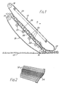
- the principal working elements of this form of the invention comprise a pair of endless belts 10,12 trained around rollers 14,16, 18, assisted and supported by guide rollers 22 and guide bars 24 where appropriate.
- the rearward belt 10 has an upper run 26 which extends from a lower end reversing roller 16 adjacent the ground 17 to an upper end reversing roller 14 in a rearward inclination with respect to the direction of travel of the apparatus (indicated by the arrow X).
- the forward belt 12 has a lower run 28 which lies face-to-face with the upper run 26 of the belt 10.
- a characteristic of the forward belt 12 is that it is slack.
- the belts can conveniently be made from spaced steel rods 52 secured at their ends to flexible side members 54. This construction is particularly convenient as the spacing of the rods allows dirt, leaves, grass and other debris to fall through, and the rods can also engage sprockets, for example on the rollers 14,18, ensuring that the belts are driven at the correct speed.
- the belts could be of some other construction, e.g. solid rubber webbing.
- the apparatus is mounted on a conventional agricultural tractor 100, comprising a chassis 102, front wheels 104 and rear wheels 106, and a conventional three-point mounting 108 and power take-off point 110 at the rear.
- a conventional agricultural tractor 100 comprising a chassis 102, front wheels 104 and rear wheels 106, and a conventional three-point mounting 108 and power take-off point 110 at the rear.
- the harvesting machine frame is mounted on the tractor in suitable manner.
- the frame is not shown in any detail, but comprises a framework of appropriate shape to support the various components shown.
- the power take-off from the tractor powers a hydraulic pump 112 which supplies a preset output power to a hydraulic motor (not shown) connected to ground wheels 38 on the frame of the harvesting machine.
- a hydraulic pump 112 which supplies a preset output power to a hydraulic motor (not shown) connected to ground wheels 38 on the frame of the harvesting machine. This ensures that there is enough power supplied to these wheels, and to the associated belts 10,12, so that they move at ground speed without tending to slew the machine around; but not too much power so that the friction between the ground wheels and the ground is overcome and the belts run too quickly.
- the ground wheel 38 is suitably linked by a chain 114 to the upper end reversing roller 18 of the belt 12 and to a sprocket roller 25 biased by a spring 29 into engagement with the lower run of the belt 10.
- a chain 114 to the upper end reversing roller 18 of the belt 12 and to a sprocket roller 25 biased by a spring 29 into engagement with the lower run of the belt 10.
- the lower end portion 27 of the belt 12 may move in a rearward direction relative to the ground, causing the apples 50 to be moved towards the nip between the face-to-face region of the belts. It is desirable that any rearward movement is not too large, or damage to the apples 50 may result. It has been found that satisfactory results are obtained if the rearward speed of the lower end portion 22 relative to the ground is about 10% of the forward speed of the machine over the ground.
- the lower end reversing roller 16 of the rear belt 10 is journalled at its ends to arms 21 which are pivoted at 19 to the frame of the machine so that the roller 16 can be displaced to follow undulations in the ground, as indicated by the full and phantom lines.
- the apples When the apples are discharged from the top of the belts 10,12, they fall a short distance onto a cleaning belt 44, which is provided over its surface with resilient radially projecting fingers 46, for example of rubber, so that it has the form of a coarse brush.
- the fingers are sufficiently long and resilient as to break the fall of the apples without bruising them, but not sufficient to support the apples and carry them around with the rotation of the belt.
- the belt is arranged to rotate in the direction as shown by the arrow, while the apples fall on the upwardly moving upper surface of the belt.
- the apples continue their downward fall, slowed by the belt and brushed by the fingers 46 which entrain dirt, leaves etc., and discharge this debris from the upper end of the belt, a resilient flap 47 blocking any apples, and a cleaning flap 49 removing the debris.
- the apples fall from the belt 44 onto a transverse conveyor 56 having flights 57 which entrain the apples.
- the conveyor lifts the apples up to discharge them onto a rearward conveyor 59 which extends over the top 61 of a trailer towed by the tractor and into which the apples are finally discharged.
- the drive to the belt 10 may be positioned at the location of the sprocket roller 25, in a position such that the drive sprocket is pressed slightly into the belt 10 to ensure good engagement.
- This may be improved by having the upper part of the belt 10 (above the upper guide roller 22) inclined at a smaller angle to the ground relative to the rest of the belt 10. This also has the advantage of bringing the top of the belt 10 closer to the cleaning belt 44.
- the roller 16 may be fixed, rather than journalled to pivot at 19.
- the belt pick-up mechanism is mounted on the tractor by a series of pivoted link arms 63, so that the mechanism can be moved by hydraulic rams (not shown) into three positions.
- the first position A shown in full lines is the normal operative position.
- the belts 10,12 and ground wheels 38 are lifted clear of the ground, but continue to operate, so that any fruit in the belts is cleared and discharged into the trailer.
- the third position C the belts 10,12 are swung upwards so as to reduce the width of the machine for transport. In this condition the belts are not moving.
- FIG. 6 shows the basic two-belt arrangement of Fig. 1 with a modification provided by a scavenger roller 150 located just in front of the lower roller 16 of the lower belt 10, in the wedge-shaped gap between the roller and the ground.
- the scavenger roller rotates about a transverse axis, and is driven, preferably at a speed rather greater than that of the roller 16, in the direction indicated so as to flick the articles being harvested forwards and upwards into the nip between the belts.
- the scavenger roller can be for example of square cross-section, or have peripheral bristles, or axially extending flexible vanes 152 (as shown). This modification is particularly appropriate for harvesting small articles such as nuts which would otherwise tend to wedge in the space between the roller 16 and the ground, being appreciably smaller than the smallest practicable radius for the roller 16.
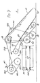
- Fig. 7 shows another embodiment of the invention, currently preferred. It is generally similar to the embodiment shown in Fig. 3, and the same reference numerals are used to indicate corresponding parts, where appropriate, and repeated explanation will not be given, except where necessary to understand the differences between the embodiments of Figs. 3 and 7.
- Figs. 7 The main difference between the embodiments of Figs. 3 and 7 concern the drive of belt 10.
- the drive is not via roller 14, but via a roller 501 which is positioned below the belt 10, and engages with it.
- the ground roller 38 controls the speed of the chain 114, and also the belt 10, as the chain 114 passes round roller 501.
- the chain 114 also passes round roller 18, hence controlling the speed of the belt 12.
- the upper run of the belt 10 is not straight, but instead the upper part has a smaller angle of inclination relative to the ground (e.g. 20°) than the lower part (e.g. 38°).
- the cleaning belt 44 is driven by a vee belt 503 extending between roller 18 and one of the rollers 504 of the cleaning belt 44.
- a vee belt 503 extending between roller 18 and one of the rollers 504 of the cleaning belt 44.
- the entire machine has a single drive system since the drive to chain 114 controls all three belts 10,12,44.
- the drive system is simplified relative to other embodiments.
- the machine may be driven so that the forward loop 27 of the belt 12 is stationary relative to the ground, or may move rearwardly (i.e. in the opposite direction to arrow X) if desired, as discussed above.
- Fig. 7 also shows the support strips 505 for the transverse conveyor 56, which again has flights 57.
- the gap 506 between the roller 14 at the top of belt 10 and the roller 507 of the cleaning belt 44 is adjustable depending on the density of the articles being gathered, to ensure that an even distribution reaches the conveyor 56.
- a pair of contra-rotating brushes may be provided at the forward corners of the pick-up frame to gather fruit from relatively inaccessible places and sweep them into the path of the gathering belts.
- the belts have been described as travelling at the same speed, it may be preferred to have them travelling at slightly different speeds so that a scrubbing action is imparted to the fruit to help clean it. This can be easily arranged by having slight differences in the diameters of the sprockets shown for example in Fig. 3.
- the invention has been exemplified in relation to gathering fruit from the ground, it can be applied to gathering other articles, such as balls, from the ground or other surface.
Landscapes
- Life Sciences & Earth Sciences (AREA)
- Environmental Sciences (AREA)
- Structure Of Belt Conveyors (AREA)
- Apparatuses For Bulk Treatment Of Fruits And Vegetables And Apparatuses For Preparing Feeds (AREA)
- Harvesting Machines For Specific Crops (AREA)
Claims (7)
- Maschine zum Aufsammeln von Gegenständen vom Boden, umfassend ein Fahrgestell zur Vorwärtsfahrt auf dem Boden, eine Aufnahmeeinrichtung mit einem vorderen Teil (12) und einem hinteren Teil (10) auf Bodenhöhe, die jeweils ein Teil aufweisen, das mit dem Fahrgestell um eine quer zur Fahrtrichtung horizontale Achse schwenkbar verbunden ist, und die einen Spalt bilden, in den die Gegenstände eingezogen werden können, und Mittel (112, 114) zum Antreiben der Aufnahmeteile im Gegenlauf, wenn sich die Maschine über den Boden bewegt, wobei der Antrieb der Teile mit der Vorwärtsbewegung der Maschine auf dem Boden verknüpft ist, so daß sich der mit dem Boden in Eingriff stehende Bereich (27) des vorderen Teils (12) gegenüber dem Boden nicht mit positiver Geschwindigkeit (in Vorwärtsrichtung) bewegt,
dadurch gekennzeichnet, daß die Aufnahmeteile endlose Bänder (10, 12) umfassen, wobei das vordere Band (12) einen durchhängenden unteren Abschnitt (28) aufweist, der auf einem oberen Abschnitt des hinteren Bandes (10) aufliegt, und eine durchhängende Schlaufe (27) am unteren Endbereich aufweist, die vor dem hinteren Band (10) auf dem Boden aufliegt. - Maschine nach Anspruch 1, wobei die Bänder (10, 12) aus einer Reihe von Querstangen (52) gebildet sind, die im gegenseitigen Abstand angeordnet und durch flexible Gurte (54) miteinander verbunden sind.
- Maschine nach Anspruch 1 oder 2, wobei das hintere endlose Band (10) eine untere Umlenkrolle (16) aufweist, die an ihren Enden in nach oben auslenkbaren Lagerteilen gelagert ist, so daß die Umlenkrolle Bodenunebenheiten folgen kann.
- Maschine nach einem der vorhergehenden Ansprüche, wobei unmittelbar vor dem hinteren endlosen Band eine Abführrolle (150) über dem Boden angeordnet ist, wobei die Abführrolle (150) um eine Querachse verdrehbar und mit einer Geschwindigkeit antreibbar ist, die größer ist als diejenige des hinteren endlosen Bandes, aber zu dieser gleichsinnig ist, um kleine Gegenstände nach vorne und nach oben in den Spalt zwischen dem vorderen und dem hinteren endlosen Band (12, 10) zu schleudern.
- Maschine nach einem der vorhergehenden Ansprüche, wobei der Antrieb der Aufnahmeteile mit der Drehbewegung eines Bodenrades (38) verknüpft ist, das von einem hydraulischen Pumpenmotor (112) angetrieben wird, der eine bestimmte Maximalleistung abgibt, um zu gewährleisten, daß sich das Bodenrad entsprechend der Geschwindigkeit über Grund verdreht, ohne die Vorwärtsbewegung der Maschine zu beschleunigen oder unmäßig zu bremsen.
- Maschine nach Anspruch 5, wobei die Aufnahmeteile (10 12) und das Bodenrad (38) an der Längsseite einer Zugmaschine (100) anbringbar sind.
- Maschine nach einem der vorhergehenden Ansprüche, wobei die enlosen Bänder zwischen einer mit dem Boden in Berührung stehenden Betriebsstellung und einer angehobenen Stellung bewegbar sind, in der sie sich über dem Boden befinden, aber weiter umlaufen können, um mitgenommene Gegenstände zu beseitigen.
Applications Claiming Priority (6)
| Application Number | Priority Date | Filing Date | Title |
|---|---|---|---|
| GB858509965A GB8509965D0 (en) | 1985-04-18 | 1985-04-18 | Fruit gathering machine |
| GB8509965 | 1985-04-18 | ||
| GB8527036 | 1985-11-02 | ||
| GB858527036A GB8527036D0 (en) | 1985-11-02 | 1985-11-02 | Machine for gathering fruit &c |
| GB868601888A GB8601888D0 (en) | 1986-01-27 | 1986-01-27 | Machine for gathering fruit &c |
| GB8601888 | 1986-01-27 |
Publications (3)
| Publication Number | Publication Date |
|---|---|
| EP0202766A2 EP0202766A2 (de) | 1986-11-26 |
| EP0202766A3 EP0202766A3 (en) | 1988-02-24 |
| EP0202766B1 true EP0202766B1 (de) | 1991-12-11 |
Family
ID=27262653
Family Applications (1)
| Application Number | Title | Priority Date | Filing Date |
|---|---|---|---|
| EP86302827A Expired EP0202766B1 (de) | 1985-04-18 | 1986-04-16 | Maschine zum Einsammeln von Früchten oder dergleichen |
Country Status (11)
| Country | Link |
|---|---|
| US (1) | US4722175A (de) |
| EP (1) | EP0202766B1 (de) |
| AU (1) | AU580933B2 (de) |
| BR (1) | BR8601689A (de) |
| CA (1) | CA1247374A (de) |
| DE (1) | DE3682823D1 (de) |
| ES (1) | ES8707076A1 (de) |
| GB (1) | GB2173684B (de) |
| IL (1) | IL78504A0 (de) |
| NZ (1) | NZ215853A (de) |
| PT (1) | PT82419B (de) |
Families Citing this family (24)
| Publication number | Priority date | Publication date | Assignee | Title |
|---|---|---|---|---|
| JP2655517B2 (ja) * | 1987-06-16 | 1997-09-24 | フランツ メディカル ディベロプメント リミテッド | 経口/非経口的流体制御及び注入用ポンプ装置 |
| US5247717A (en) * | 1989-10-23 | 1993-09-28 | Owen Smith | Debris/litter collecting apparatus |
| FR2709041A1 (fr) * | 1993-08-16 | 1995-02-24 | Fitamant Hubert | Ramasseuse d'échalotes. |
| FR2718323B1 (fr) * | 1994-04-11 | 1996-06-28 | Joel Poussin | Machine pour le ramassage de produits au sol tels que des fruits. |
| US5745947A (en) * | 1996-01-30 | 1998-05-05 | The Toro Company | Automatic debris retrieval system |
| FR2766659B1 (fr) * | 1997-07-30 | 1999-09-03 | Jean Pierre Lacombe | Dispositif pour le ramassage de fruits sur le sol |
| DE19749960C2 (de) * | 1997-11-03 | 2000-06-08 | Horst Staiger & Soehne Gmbh | Fördereinrichtung für Rasenmäher und Kehrmaschinen |
| US6779329B2 (en) * | 2000-09-21 | 2004-08-24 | Pik Rite, Inc. | Vinous crop harvesting apparatus and method |
| FR2819149B1 (fr) * | 2001-01-08 | 2003-04-11 | Sebastien Carlier | Automoteur equipe d'un tablier rotatif a brosses destine a reunir la nourriture des bovins, ovins, caprins sur une table d'alimentation |
| ATE425659T1 (de) * | 2001-01-22 | 2009-04-15 | Pellenc Iberica S L | Vorrichtung zum sammeln von landwirtschaftlichen, am boden liegenden produkten, insbesondere von kleinen fruchten |
| CA2631888A1 (en) * | 2004-12-10 | 2006-06-15 | Innotech Pty Ltd | Guide and agricultural machine incorporating same |
| US20130064611A1 (en) * | 2009-06-15 | 2013-03-14 | Picker Technologies Llc | Dry decelerator for apples or like objects |
| CN102639413A (zh) * | 2010-07-16 | 2012-08-15 | 匹克技术公司 | 用于苹果或类似物品的干式减速器 |
| CN102910407A (zh) * | 2010-07-16 | 2013-02-06 | 匹克技术公司 | 用于苹果或类似物品的干式减速器 |
| US9078468B2 (en) | 2013-01-15 | 2015-07-14 | Dole Fresh Vegtables, Inc. | Leaf removal apparatus |
| US9144197B2 (en) | 2013-11-04 | 2015-09-29 | Cnh Industrial America Llc | Dual conveyor infeed for a header of an agricultural harvester |
| US11818983B2 (en) | 2014-09-21 | 2023-11-21 | Bridgestone Corporation | Guayule harvester and related processes |
| US9836661B2 (en) * | 2014-12-04 | 2017-12-05 | General Electric Company | System and method for collision avoidance |
| BR112017007707B1 (pt) * | 2014-12-10 | 2021-05-04 | Agco Corporation | ceifeira operável para ser avançada ao longo de uma superfície de terreno |
| EP3500084A4 (de) * | 2016-09-21 | 2020-06-17 | Abundant Robotics, Inc. | Systeme für robotisches ernten |
| TWI646887B (zh) * | 2017-08-23 | 2019-01-11 | 行政院農業委員會桃園區農業改良場 | Vegetable harvester transfer device |
| JP7606887B2 (ja) * | 2021-03-03 | 2024-12-26 | エア・ウォーター株式会社 | 収穫機 |
| JP7504047B2 (ja) * | 2021-03-08 | 2024-06-21 | ヤンマーホールディングス株式会社 | 農作物収穫作業機 |
| WO2024026070A2 (en) * | 2022-07-29 | 2024-02-01 | The Regents Of The University Of California | Produce pickup system |
Family Cites Families (24)
| Publication number | Priority date | Publication date | Assignee | Title |
|---|---|---|---|---|
| US2639573A (en) * | 1950-05-08 | 1953-05-26 | Mclaughlin Alvin | Nut harvesting machine |
| US2664691A (en) * | 1950-08-04 | 1954-01-05 | Wiebe Walter | Apparatus for picking up prunes and the like |
| FR1028605A (fr) * | 1950-11-29 | 1953-05-26 | Chargeuse de betteraves | |
| US2843994A (en) * | 1956-07-06 | 1958-07-22 | Joseph P Gomes | Vegetable top cleaning machine |
| US2928225A (en) * | 1958-11-10 | 1960-03-15 | Spencer Donnell | Harvesting machine for fruit and nuts |
| US2993322A (en) * | 1959-08-27 | 1961-07-25 | Wiebe Walter | Fruit harvester for picking up fruit off the ground |
| US3390768A (en) * | 1965-02-19 | 1968-07-02 | Robert L. Button | Tomato harvesting apparatus |
| US3292806A (en) * | 1965-03-25 | 1966-12-20 | Robert V Maag | Harvester |
| US3928534A (en) * | 1965-09-24 | 1975-12-23 | Degussa | Catalyst useful at higher temperatures, especially for purification of exhaust gases from motor vehicles and industrial plants |
| US3420312A (en) * | 1966-07-18 | 1969-01-07 | Fmc Corp | Harvester cutting mechanism |
| US3353342A (en) * | 1966-07-20 | 1967-11-21 | Univ California | Harvester pickup |
| US3518819A (en) * | 1967-02-13 | 1970-07-07 | Lockwood Corp | Brush pickup |
| US3678677A (en) * | 1970-08-13 | 1972-07-25 | Fmc Corp | De-vining melons |
| US3800518A (en) * | 1971-10-20 | 1974-04-02 | Agriframe Inc | Lettuce harvester |
| US3872657A (en) * | 1973-07-20 | 1975-03-25 | Ramacher Mfg Co | Harvester pick-up |
| US4014390A (en) * | 1974-02-13 | 1977-03-29 | Teixeira Antone S | Beach cleaner apparatus |
| US3993141A (en) * | 1974-11-18 | 1976-11-23 | Donohue Paul C | Pin cylinder litter collector |
| US4077533A (en) * | 1976-08-16 | 1978-03-07 | John Meyer | Tennis ball retrieving device |
| US4188772A (en) * | 1977-06-06 | 1980-02-19 | Harrington Manufacturing Company | Hydraulic speed control system for the pick-up reel of a peanut combine |
| US4234045A (en) * | 1978-11-20 | 1980-11-18 | Porter-Way Harvester Manufacturing Co., Inc. | Harvesting machine feeder apparatus |
| FR2449395A1 (fr) * | 1979-02-26 | 1980-09-19 | Matrot Louis | Avaleur perfectionne pour machines de recolte |
| US4434011A (en) * | 1982-03-15 | 1984-02-28 | Proficient Systems, Inc. | Method and apparatus for retrieving objects from the ground |
| US4593426A (en) * | 1983-11-25 | 1986-06-10 | Caravelle Industries, Inc. | Litter collection apparatus |
| US4642977A (en) * | 1985-11-01 | 1987-02-17 | Ramacher Manufacturing Company | Trash separator for hut harvester |
-
1986
- 1986-04-14 US US06/851,549 patent/US4722175A/en not_active Expired - Fee Related
- 1986-04-15 IL IL78504A patent/IL78504A0/xx not_active IP Right Cessation
- 1986-04-15 BR BR8601689A patent/BR8601689A/pt unknown
- 1986-04-16 CA CA000506871A patent/CA1247374A/en not_active Expired
- 1986-04-16 GB GB08609298A patent/GB2173684B/en not_active Expired
- 1986-04-16 NZ NZ215853A patent/NZ215853A/xx unknown
- 1986-04-16 EP EP86302827A patent/EP0202766B1/de not_active Expired
- 1986-04-16 DE DE8686302827T patent/DE3682823D1/de not_active Expired - Fee Related
- 1986-04-17 PT PT82419A patent/PT82419B/pt not_active IP Right Cessation
- 1986-04-18 AU AU56353/86A patent/AU580933B2/en not_active Ceased
- 1986-04-18 ES ES554665A patent/ES8707076A1/es not_active Expired
Also Published As
| Publication number | Publication date |
|---|---|
| DE3682823D1 (de) | 1992-01-23 |
| ES554665A0 (es) | 1987-07-16 |
| GB8609298D0 (en) | 1986-05-21 |
| AU5635386A (en) | 1986-10-23 |
| AU580933B2 (en) | 1989-02-02 |
| IL78504A0 (en) | 1986-08-31 |
| GB2173684B (en) | 1988-10-19 |
| PT82419B (pt) | 1991-10-31 |
| US4722175A (en) | 1988-02-02 |
| ES8707076A1 (es) | 1987-07-16 |
| EP0202766A2 (de) | 1986-11-26 |
| EP0202766A3 (en) | 1988-02-24 |
| PT82419A (en) | 1986-05-01 |
| NZ215853A (en) | 1988-07-28 |
| BR8601689A (pt) | 1986-12-16 |
| CA1247374A (en) | 1988-12-28 |
| GB2173684A (en) | 1986-10-22 |
Similar Documents
| Publication | Publication Date | Title |
|---|---|---|
| EP0202766B1 (de) | Maschine zum Einsammeln von Früchten oder dergleichen | |
| US4234045A (en) | Harvesting machine feeder apparatus | |
| US5287687A (en) | Harvesting apparatus | |
| US3986561A (en) | Tomato harvester | |
| US5375403A (en) | Lowbush berry harvester | |
| US3986324A (en) | Melon pickup and loading machine | |
| US3626677A (en) | Mechanical harvester | |
| IES67004B2 (en) | Crop cleaner | |
| US4984421A (en) | Process and machine for harvesting fruits or similar items scattered on the ground | |
| CA2100204A1 (en) | Picking head for lowbush berry harvester | |
| US3712039A (en) | Crop pick-up harvester | |
| EP0548192B1 (de) | Knollenscheider | |
| US4211062A (en) | Machine for harvesting agricultural produce | |
| US7536848B2 (en) | Article pickup apparatus | |
| US3426515A (en) | Cabbage harvester | |
| US3241619A (en) | Peanut and bean harvester | |
| US4480349A (en) | Particulate collecting apparatus | |
| US3521734A (en) | Article pickup machine for raisin trays and the like | |
| US3427794A (en) | Mobile cucumber harvester | |
| US3780511A (en) | Trash separator for crop pick-up harvester | |
| SU1482584A1 (ru) | Устройство дл уборки кормовых корнеплодов | |
| JP3874541B2 (ja) | 収穫機 | |
| JP2868182B2 (ja) | 根菜類の収穫装置 | |
| JP2000032824A (ja) | 収穫機及び、収穫機の選別コンベア | |
| US3205949A (en) | Rock-gathering machine |
Legal Events
| Date | Code | Title | Description |
|---|---|---|---|
| PUAI | Public reference made under article 153(3) epc to a published international application that has entered the european phase |
Free format text: ORIGINAL CODE: 0009012 |
|
| AK | Designated contracting states |
Kind code of ref document: A2 Designated state(s): AT BE CH DE FR IT LI LU NL SE |
|
| RAP1 | Party data changed (applicant data changed or rights of an application transferred) |
Owner name: SOMERSET FRUIT MACHINERY LIMITED |
|
| RIN1 | Information on inventor provided before grant (corrected) |
Inventor name: HOBHOUSE, HENRY |
|
| PUAL | Search report despatched |
Free format text: ORIGINAL CODE: 0009013 |
|
| AK | Designated contracting states |
Kind code of ref document: A3 Designated state(s): AT BE CH DE FR IT LI LU NL SE |
|
| RIN1 | Information on inventor provided before grant (corrected) |
Inventor name: HOBHOUSE, HENRY |
|
| 17P | Request for examination filed |
Effective date: 19880817 |
|
| 17Q | First examination report despatched |
Effective date: 19900306 |
|
| GRAA | (expected) grant |
Free format text: ORIGINAL CODE: 0009210 |
|
| AK | Designated contracting states |
Kind code of ref document: B1 Designated state(s): DE FR |
|
| REF | Corresponds to: |
Ref document number: 3682823 Country of ref document: DE Date of ref document: 19920123 |
|
| ET | Fr: translation filed | ||
| PLBE | No opposition filed within time limit |
Free format text: ORIGINAL CODE: 0009261 |
|
| STAA | Information on the status of an ep patent application or granted ep patent |
Free format text: STATUS: NO OPPOSITION FILED WITHIN TIME LIMIT |
|
| 26N | No opposition filed | ||
| PGFP | Annual fee paid to national office [announced via postgrant information from national office to epo] |
Ref country code: DE Payment date: 19950419 Year of fee payment: 10 |
|
| PG25 | Lapsed in a contracting state [announced via postgrant information from national office to epo] |
Ref country code: DE Effective date: 19970101 |
|
| PGFP | Annual fee paid to national office [announced via postgrant information from national office to epo] |
Ref country code: FR Payment date: 20000417 Year of fee payment: 15 |
|
| PG25 | Lapsed in a contracting state [announced via postgrant information from national office to epo] |
Ref country code: FR Free format text: THE PATENT HAS BEEN ANNULLED BY A DECISION OF A NATIONAL AUTHORITY Effective date: 20010430 |
|
| REG | Reference to a national code |
Ref country code: FR Ref legal event code: ST |