EP0366167A2 - Réceptacle pour papier plié en accordéon - Google Patents
Réceptacle pour papier plié en accordéon Download PDFInfo
- Publication number
- EP0366167A2 EP0366167A2 EP89202358A EP89202358A EP0366167A2 EP 0366167 A2 EP0366167 A2 EP 0366167A2 EP 89202358 A EP89202358 A EP 89202358A EP 89202358 A EP89202358 A EP 89202358A EP 0366167 A2 EP0366167 A2 EP 0366167A2
- Authority
- EP
- European Patent Office
- Prior art keywords
- trough
- paper
- stack
- sheets
- carrier
- Prior art date
- Legal status (The legal status is an assumption and is not a legal conclusion. Google has not performed a legal analysis and makes no representation as to the accuracy of the status listed.)
- Withdrawn
Links
Images


Classifications
-
- B—PERFORMING OPERATIONS; TRANSPORTING
- B65—CONVEYING; PACKING; STORING; HANDLING THIN OR FILAMENTARY MATERIAL
- B65H—HANDLING THIN OR FILAMENTARY MATERIAL, e.g. SHEETS, WEBS, CABLES
- B65H1/00—Supports or magazines for piles from which articles are to be separated
- B65H1/02—Supports or magazines for piles from which articles are to be separated adapted to support articles on edge
- B65H1/025—Supports or magazines for piles from which articles are to be separated adapted to support articles on edge with controlled positively-acting mechanical devices for advancing the pile to present the articles to the separating device
-
- B—PERFORMING OPERATIONS; TRANSPORTING
- B41—PRINTING; LINING MACHINES; TYPEWRITERS; STAMPS
- B41J—TYPEWRITERS; SELECTIVE PRINTING MECHANISMS, i.e. MECHANISMS PRINTING OTHERWISE THAN FROM A FORME; CORRECTION OF TYPOGRAPHICAL ERRORS
- B41J11/00—Devices or arrangements of selective printing mechanisms, e.g. ink-jet printers or thermal printers, for supporting or handling copy material in sheet or web form
- B41J11/58—Supply holders for sheets or fan-folded webs, e.g. shelves, tables, scrolls, pile holders
-
- B—PERFORMING OPERATIONS; TRANSPORTING
- B65—CONVEYING; PACKING; STORING; HANDLING THIN OR FILAMENTARY MATERIAL
- B65H—HANDLING THIN OR FILAMENTARY MATERIAL, e.g. SHEETS, WEBS, CABLES
- B65H31/00—Pile receivers
- B65H31/02—Pile receivers with stationary end support against which pile accumulates
-
- B—PERFORMING OPERATIONS; TRANSPORTING
- B65—CONVEYING; PACKING; STORING; HANDLING THIN OR FILAMENTARY MATERIAL
- B65H—HANDLING THIN OR FILAMENTARY MATERIAL, e.g. SHEETS, WEBS, CABLES
- B65H2701/00—Handled material; Storage means
- B65H2701/10—Handled articles or webs
- B65H2701/11—Dimensional aspect of article or web
- B65H2701/112—Section geometry
- B65H2701/1123—Folded article or web
- B65H2701/11231—Fan-folded material or zig-zag or leporello
Definitions
- This invention is directed to a Z-fold computer paper carrier for storing a stack of folded continuous paper sheets which are fed into a printer mechanism and for refolding printed-on sheets of that stack which have exited the printer mechanism. More particularly, the invention is directed to a free-standing Z-fold paper sheets carrier with tiered paper stack-holding troughs.
- Multi-folded and edge perforated stacks of computer paper are extensively used in stand-alone computer printers and in computers which have an integrated printing/plotting mechanism.
- folded paper sheets are fed direct from the paperboard box containing the Z-fold sheets or provision is made on the printer itself to hold a stack of continuous multi-folded edge perforated sheets of computer paper in a suitable rack.
- the type of stack is generally known interchangeably as Z-fold or fan-folded paper.
- the term Z-fold will be used herein to describe the type of paper stack which is carried by and refolded by the carrier of the invention.
- printed-on paper is not refolded automatically but rather just exits from the rear of the printer and falls to an adjacent floor or to the rear of the printer and the operator/user must then pick-up and manually refold the whole stack or separate portions of the continuous stack into several smaller refolded stacks for subsequent use or storage.
- printer stands which include an acrylic plastic folded paper storage box placed on a work surface on top of which a printer rests and a separate acrylic plastic open catch basket resting on the same work surface for refolding the finished print out; a vinyl-coated wire box under the printer with an end-attached vinyl-coated wire catch basket extending therefrom; a double-tiered vinyl-coated wire box under the printer with stored unused continuous Z-fold paper sheets in a slanted top shelf and a bottom shelf for receiving refolded sheets exiting the printer; and caster-movable floor units with or without shelves for feeding and refolding Z-fold computer paper.
- Each of the above prior art carriers or systems take up as much again or more than the space dedicated to the printer housing itself or are stacked below the printer thus raising the printer in elevation above its normal workstation level. It is desirable that the level of the printer and especially a printer incorporated in a keyboard-containing computer or integrator will not be placed at a higher level than the normal level for the human user. Further, it is desired to minimize the footprint of the carrier and to make the carrier of a minimal length so that it can fit behind a printer without interference with a work surface back wall which may be as little as two feet from the front edge of the worksurface.
- the carrier should also be easily movable to provide easy access for connection and disconnection of input and output cables to the printer/computer.
- the printed-on paper continues to be visible for reading by the user as it is exiting the printing mechanism, as it is being refolded and after it has been refolded and again stacked. Further, it is advantageous to have a construction in which an operator/user can easily manually place identifying comments or indicia on the printed data as it exits the printing mechanism and before it is fully refolded without creasing, wrinkling or tearing the continuous paper sheets.
- a device which allows reversal of the unfolding/refolding action is advantageous in that it allows the refolded sheets themselves to be conveyed back into the printer mechanism exit and after refolding into the normally unprinted folded sheets holder, which are then passed a second time through the printer mechanism to perform a reprint or additional print operation (e.g. an additional color presentation) on those sheets.
- the reprinted sheets are again refolded as they reach the refolding upper trough.
- the invention described herein provides a free-standing paper carrier for unfolding and refolding connected sheets of a continuous stack of Z-folded computer paper.
- the cover is positionable at the rear of a printer housing or a computer housing having its own dedicated printer mechanism, such as a computer integrator used in chromatographic analysis systems.
- a pair of horizontally displaced tiered open troughs typically made of rod stock are provided extending across an open rod stock support frame, the lower trough being attached adjacent a rod stock carrier base which sits on the same normally flat horizontal work surface as the printer/computer to be paper fed.
- the upper trough extends forwardly and above the lower trough and above the plane of the printer mechanism paper exit for reception of the printed-on paper to be refolded and stacked therein.
- a pivotable flat paper guide ramp is provided at a top front edge of the upper trough which bridges the gap between the upper trough and the paper exit from the printer mechanism to aid in the movement of the paper sheets to the refolding upper trough.
- the ramp also provides a writing surface for the operator to manually make pencil or ink notes or other indicia on the printer exiting paper.
- the paper exiting the printer mechanism and the printed-don sheets being refolded and stacked in the upper trough may be easily read by the operator while he or she sits at the computer keyboard.
- the invention also contemplates that the troughs and frames of the carrier be constructed from injection molded or otherwise formed plastic or other sheet material.
- the Z-fold paper is unfolded from the lower trough and conveyed into the printer mechanism and subsequently the print-out is conveyed into and refolded for stacking in the upper trough.
- the paper carrier of the invention necessitates only about a six-inch (288 mm) clearance between the rear of the printer/computer housing and the back wall or end of the work bench or table forming the work surface.
- Part of the carrier base is slid under and therefore extends under the printer/computer housing and part of the upper trough and essentially all of the ramp extends above rear sections of the printer/computer housing.
- the paper carrier when empty can be easily removed or angularly moved or slightly shifted behind the printer/computer housing so as to provide for cable connection or disconnection. Room is also provided so that the printer/computer cables can be placed without interference between the rear of the printer/computer housing and a front section of the lower trough immediately above the base.
- the invention also permits the reversal of the refolded sheets operation so that the refolded sheets in the upper trough are unfolded by a reversal of the printer paper drive mechanism so that the then unfolded paper sheets pass into the printer mechanism exit and back to the lower trough where they are refolded.
- the printer paper drive mechanism is placed into normal drive operation and passes the reversed sheets back through the printer mechanism for a reprint operation and the double-printed sheets are then refolded into the upper trough.
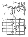
- the paper carrier 10 includes a free-standing base made up of a forward facing U-shaped rod stock portion 11 having a forward bent end 29 and a rearward facing U-shaped rod stock portion 12.
- the rod stock members may be thin steel rods nickel-plated for both appearance and corrosion resistance.
- a double pair of integral rod-stock frame members 14, 15 and 16, 17 extend upwardly from the respective U-shaped base portions angularly and forwardly.
- a first open rod stock lower trough 20 is connected across the upstanding frame members adjacent the base portions 11 and 12. The trough 20 as seen in Fig.
- each of these bent rod members are of a smaller diameter, for example 1/8 inch, than the rod stock of the base, frame members and the top edges of the troughs, which typically have a diameter of 7/32 inch.
- a series of cantilevered rod stock stubs or extensions 24 extend at an acute angle from front edge 23 for supporting paper sheets exiting the first lower trough.
- a second open upper rod stock trough 30 is connected between the outer frame members 14, 15 and 16, 17 at a position forward of and spaced above the lower trough 20.
- Trough 30 has (Fig. 3) a horizontal rearward refolded paper-holding cross-member 31, side members 32 welded to the frame members 14, 15, a front edge 33 between the side members, a pair of L-shaped members formed by the side members 32 and upward extensions 34 leading to the cross-member 31.
- the basket portions of the upper trough are formed by bent front rod stock members 35, bottom members 36 and rear members 39.
- the L-shaped members prevent lateral movement of the refolded paper sheets and act as an arm forwardly of the plane in which the bottommost refolded sheets are stacked in trough 30 against the rear rod stock member 39 of the trough and upstanding U-shaped trough stack supports 37 extending from cross-member 31.
- the forward bent edge 29 of base 11 extends forwardly of both troughs 20 and 30 to give stability to the base and to provide a portion which is extendable under the rear bottom edge of a printer or computer housing (Fig. 2).
- Extending from the top front edge 33 of the upper trough is a guide ramp 40 pivotable thereon for bridging a gap between the paper exit on the printer mechanism and the front top edge of the upper trough.
- the reverse side of the ramp (Figs. 5-6) has a series of, typically three, L-shaped mounting clips, either screw-mounted or integral with the ramp for interference fit clip-on with the upper trough front top edge 33.
- An edge bevel 44 (Fig.
- the ramp may be made of transparent Lexan polycarbonate plastic slightly wider, e.g. 9 3/4 inch wide, than the 9 1/2 inch standard width of one size of Z-fold paper including its removable side perforations which interact with the printer paper drive mechanism.
- the ramp typically about 1/8 inch thick has a top flat obverse surface about 3 inches wide adjacent bevel 44 which permits a user to manually write notes or place indicia on the paper print-out exiting from the printer paper exit.
- the top front edge 33 of the upper trough is typically about 1 3/4 inches above the feed and exit plane which thus permits reverse operation of the printer and the unfolding/refolding carrier.
- the particular size of carrier and its components is dependent on the size and number of computer paper sheets and the particular type of printer(s) or apparatus including a printer mechanism which is to be fed from the folded sheets stack.
- Fig. 2 illustrates the invention in actual use with a computer terminal 3 having a keyboard 2 positioned on a horizontal work surface 4 having a back vertical wall 5.
- the paper sheets carrier 10 is positioned between the rear of computer or printer housing and the back wall 5 in a space as little as six inches wide.
- the bent end 29 of base portion 11 is slidable under the rear of computer toward the front keyboard in an amount so that the upper trough 30 and particularly the pivoted ramp 40 extend over the top rear of the computer housing.
- the lower front edge of trough 30 has a clearance of about 1/4 inch from the computer/printer housing. The ramp is then pivoted to a position juxtaposed to the printer paper exit.
- a stack 6 of Z-folded computer paper such as 500 sheets is placed in lower trough 20 and the first sheet 7 fed as shown by the arrow into the printer mechanism (not shown).
- the printed-on sheet 8 (the printout) exits the printer as shown by the arrow where it passes over and parallel to the pivoted ramp 40 and is automatically refolded as it is pushed by the printer paper drive mechanism (not shown) into the upper trough 30 to form a refolded paper sheets stack 9.
- the sheet 8 can be pushed against ramp 40 and indicia written on the sheet on-the-run without interfering with the overall flow of paper sheets into and out of the printer mechanism.
- Lower trough 20 is configured to form a transverse channel 60 rearward of the computer housing suitable for conveying cables (not shown) for connection to sockets at the rear of the computer or printer housing and above base 29 and the work surface 4.
- Trough bottoms 26, 36 have an upward slope of about 5° to 15°, directed forwardly and rearwardly, respectively, to aid the unfolding and refolding of the paper sheets and to prevent buckling of the stack.
- the trough bottoms may be curved but the preferred embodiment construction includes bottom angular sections which result in less frictional slide surfaces and provide a carrier in which both the folded supply sheets in trough 20 and the refolded printout sheets in trough 30 essentially are in a laid back vertical position resting at about a 7° to 15° rearward angle from the vertical against the stack support 27,37.
- This essentially vertical stack orientation allows the foreshortening of the overall carrier and the resultant small footprint of the carrier.
- the upper trough is sized to accommodate about 150 refolded paper sheets since it is rare that a computer printer run is more than about 100 sheets before the user tears off a desired number of pages of print-out and removes the stack from the upper trough.
- chromatographic usages such as in the chemical, environmental research and monitoring, and process control fields, this covers a normal unattended chromatograph run.
- Figs. 3 and 4 illustrate in detail the carrier base, the frame members and the lower and upper troughs.
- the angularity of each bent portion of this preferred embodiment are to scale and have the same reference numerals as those in Fig. 1.
- Particularly shown in Fig. 4 is the clip-on ramp 40 with clips 41 pivotably mounted on upper trough front upper edge 33.
- Fig. 5 illustrates the rectangular configuration of ramp 40 which also includes integral L-clips 41 and a series of edge slots 43 which allow for passage of the ramps past rods 35, when the ramp is pivoted downwardly for use or upwardly for storage, if desired.
- Fig. 6 an interference fit between clip 41 and the fixed edge 33 of the upper trough is seen as well as the bevelled edge 44 of the ramp.
- Fig. 7 shows a second embodiment of the invention where the paper carrier 50 includes a rectangular base 51 which supports a pair of spaced vertical members 54 upstanding from the sides of the base.
- a lower paper unfolding trough 55 is welded to the members 54 with a majority of the trough rearward of members 54 while on upper paper refolding trough 56 has a majority of its construction extending forwardly of the members 54.
- paper stack supports 57, 59 extend upwardly from the rear of each respective trough.
- a bent arm 58 on each side of the upper trough prevents lateral movement of the refolded paper sheets.
- Figs. 8 and 9 illustrate a rod frame adjustment feature which allows the carrier to be used and adjusted to a particular height of a printer or computer printer mechanism being employed.
- Frame members 14-17 of Figs. 1-4 are modified so that each side frame is provided with a pair of telescoping portions 60,61 which are movable with respect to one another.
- the lower loop portion 61 extends from a carrier base 63.
- the upper loop (U-shaped) portion is movable upward or downward on portion 61 to adjust the height of the upper trough mounted on portion 60 in accord with the exit height of the printer mechanism.
- the lower end of portion 60 has a laterally offset U-shaped bottom 62 through which the exterior periphery of the portion 61 pass.
- a clamp comprising a threaded aperture clamping plate 64 and a screw and knob 65 are tightened on clamp plate 64a so that plates 64 and 64a are clamped against the opposite sides of both portions 60,61 to hold the portions in fixed vertical alignment.
- Fig. 9 shows this clamping action.
- Fig. 10 shows a carrier construction of a third embodiment in which a pair of plastic sheet members 70 provide the side frames of the carrier.
- Members 70 each comprise a vertical forward thrusting portion 71, integral lower and upper trough supporting side pieces 72, 73, respectively, an integral upper trough stack support side piece 75 and an integral carrier base side piece 76.
- a lower trough stack support 74 is attached to base 76 and the rear end of each side piece 72.
- cross-pieces 77 and 78 also of plastic sheet material interconnect the pair of members 70 at the ends of side pieces 72, 73 and base 76 to form the lower and upper tiered paper-holding troughs.
- Cross pieces 77, 78 are bent or molded to form the front and bottom portions of the respective troughs corresponding to the contours of rod portions 25, 26 and 35, 36 of the Figs. 1-4 embodiment.
Landscapes
- Engineering & Computer Science (AREA)
- Mechanical Engineering (AREA)
- Pile Receivers (AREA)
- Feeding Of Articles By Means Other Than Belts Or Rollers (AREA)
- Folding Of Thin Sheet-Like Materials, Special Discharging Devices, And Others (AREA)
- Handling Of Continuous Sheets Of Paper (AREA)
Applications Claiming Priority (2)
| Application Number | Priority Date | Filing Date | Title |
|---|---|---|---|
| US262924 | 1988-10-26 | ||
| US07/262,924 US4923188A (en) | 1988-10-26 | 1988-10-26 | Z-fold paper sheet carrier |
Publications (2)
| Publication Number | Publication Date |
|---|---|
| EP0366167A2 true EP0366167A2 (fr) | 1990-05-02 |
| EP0366167A3 EP0366167A3 (fr) | 1990-06-13 |
Family
ID=22999658
Family Applications (1)
| Application Number | Title | Priority Date | Filing Date |
|---|---|---|---|
| EP89202358A Withdrawn EP0366167A3 (fr) | 1988-10-26 | 1989-09-19 | Réceptacle pour papier plié en accordéon |
Country Status (3)
| Country | Link |
|---|---|
| US (1) | US4923188A (fr) |
| EP (1) | EP0366167A3 (fr) |
| JP (1) | JPH02212179A (fr) |
Cited By (1)
| Publication number | Priority date | Publication date | Assignee | Title |
|---|---|---|---|---|
| EP0731048A1 (fr) * | 1995-03-07 | 1996-09-11 | Océ-Nederland B.V. | Récepteur de matériel |
Families Citing this family (25)
| Publication number | Priority date | Publication date | Assignee | Title |
|---|---|---|---|---|
| US5039242A (en) * | 1989-12-22 | 1991-08-13 | Spectra-Physics, Inc. | Z-fold paper retainer |
| DE4008653A1 (de) * | 1990-03-17 | 1991-09-19 | Schleicher & Co Int | Zufuehreinrichtung zu einem dokumentenvernichter |
| AU111943S (en) | 1990-03-29 | 1991-08-16 | Artwright Marketing SDN BHD | A paper hopper |
| US5642951A (en) * | 1996-02-20 | 1997-07-01 | Belizario; Efren | Adjustable continuous feed printer paper collection device |
| US5727725A (en) * | 1996-10-22 | 1998-03-17 | Genicom Corporation | Fan-fold paper stacking receptacle with angled bottom and canted back wall |
| CA2200247C (fr) * | 1996-10-29 | 2004-03-16 | Thomas E. Mccue, Jr. | Systeme de manutention de papier en accordeon pour imprimante |
| US6350073B1 (en) | 1999-05-25 | 2002-02-26 | Hewlett-Packard Company | Z-fold print media handling system |
| ES2939598T3 (es) | 2011-11-10 | 2023-04-25 | Packsize Llc | Máquina de conversión elevada con guía de extracción |
| US10052838B2 (en) * | 2012-01-09 | 2018-08-21 | Packsize Llc | Converting machine with an upward outfeed guide |
| US10093438B2 (en) | 2014-12-29 | 2018-10-09 | Packsize Llc | Converting machine |
| US10850469B2 (en) | 2016-06-16 | 2020-12-01 | Packsize Llc | Box forming machine |
| JP7043426B2 (ja) | 2016-06-16 | 2022-03-29 | パックサイズ・リミテッド・ライアビリティ・カンパニー | 箱テンプレート製造システムおよび方法 |
| US11242214B2 (en) | 2017-01-18 | 2022-02-08 | Packsize Llc | Converting machine with fold sensing mechanism |
| SE541921C2 (en) | 2017-03-06 | 2020-01-07 | Packsize Llc | A box erecting method and system |
| SE1750727A1 (sv) | 2017-06-08 | 2018-10-09 | Packsize Llc | Tool head positioning mechanism for a converting machine, and method for positioning a plurality of tool heads in a converting machine |
| US11173685B2 (en) | 2017-12-18 | 2021-11-16 | Packsize Llc | Method for erecting boxes |
| US11247427B2 (en) | 2018-04-05 | 2022-02-15 | Avercon BVBA | Packaging machine infeed, separation, and creasing mechanisms |
| US11305903B2 (en) | 2018-04-05 | 2022-04-19 | Avercon BVBA | Box template folding process and mechanisms |
| WO2019246344A1 (fr) | 2018-06-21 | 2019-12-26 | Packsize Llc | Machine et systèmes d'emballage |
| SE543046C2 (en) | 2018-09-05 | 2020-09-29 | Packsize Llc | A box erecting method and system |
| US11524474B2 (en) | 2018-11-30 | 2022-12-13 | Packsize Llc | Adjustable cutting and creasing heads for creating angled cuts and creases |
| CN109544773A (zh) * | 2018-12-21 | 2019-03-29 | 北京天华嵌微信息技术有限公司 | 一种彩票销售装置 |
| WO2020146334A1 (fr) | 2019-01-07 | 2020-07-16 | Packsize Llc | Machine permettant d'ériger une boîte |
| US11701854B2 (en) | 2019-03-14 | 2023-07-18 | Packsize Llc | Packaging machine and systems |
| JP2025064606A (ja) * | 2023-10-06 | 2025-04-17 | キヤノン株式会社 | シート積載装置 |
Family Cites Families (14)
| Publication number | Priority date | Publication date | Assignee | Title |
|---|---|---|---|---|
| US2061595A (en) * | 1933-06-30 | 1936-11-24 | John Q Sherman | Typewriter attachment |
| US2845019A (en) * | 1955-05-16 | 1958-07-29 | Sperry Rand Corp | Medium speed printer |
| GB949504A (en) * | 1960-09-30 | 1964-02-12 | Lamson Paragon Ltd | Improvements in or relating to stands for continuous stationery assemblies |
| US3134474A (en) * | 1961-09-28 | 1964-05-26 | Moore Business Forms Inc | Zig-zag typewriter form stands |
| FR1327170A (fr) * | 1962-04-03 | 1963-05-17 | Appareil pour ranger les bandes de papier produites par les machines imprimantes de bureau | |
| GB1299886A (en) * | 1969-06-06 | 1972-12-13 | Alpa Steel & Plastic Ltd | Device for receiving sheets of paper or the like |
| US3712607A (en) * | 1971-04-02 | 1973-01-23 | D Ziegler | Fan-fold paper guides and stacking mechanisms |
| US4530689A (en) * | 1982-12-09 | 1985-07-23 | Crestmont Corporation | Computer paper loading-and-unloading device |
| JPS61278A (ja) * | 1984-06-12 | 1986-01-06 | Toyoda Gosei Co Ltd | 接着剤組成物 |
| GB8515939D0 (en) * | 1985-06-24 | 1985-07-24 | Xerox Corp | Restacking apparatus |
| DE3531420A1 (de) * | 1985-09-03 | 1987-03-12 | Horn Hans Dieter | Edv-drucker und einen behaelter fuer tabellierpapier enthaltende anordnung |
| ATE73709T1 (de) * | 1985-12-26 | 1992-04-15 | Bankier Companies Inc | Auffangbehaelter fuer faechergefaltete bahnen in einem drucker. |
| DE8603101U1 (de) * | 1986-02-06 | 1986-03-27 | Hebbel, Dierk, 71573 Allmersbach | Möbel mit einem EDV-Drucker und einem Behälter für Tabellierpapier |
| US4743131A (en) * | 1986-08-06 | 1988-05-10 | Atwell J Dwayne | Tractor feed continuous paper system for printers |
-
1988
- 1988-10-26 US US07/262,924 patent/US4923188A/en not_active Expired - Fee Related
-
1989
- 1989-09-19 EP EP89202358A patent/EP0366167A3/fr not_active Withdrawn
- 1989-10-26 JP JP1277320A patent/JPH02212179A/ja active Pending
Cited By (3)
| Publication number | Priority date | Publication date | Assignee | Title |
|---|---|---|---|---|
| EP0731048A1 (fr) * | 1995-03-07 | 1996-09-11 | Océ-Nederland B.V. | Récepteur de matériel |
| NL9500445A (nl) * | 1995-03-07 | 1996-10-01 | Oce Nederland Bv | Houder voor ontvangstmateriaal. |
| US5746327A (en) * | 1995-03-07 | 1998-05-05 | Oce-Nederland, B.V. | Receiving material holder |
Also Published As
| Publication number | Publication date |
|---|---|
| US4923188A (en) | 1990-05-08 |
| EP0366167A3 (fr) | 1990-06-13 |
| JPH02212179A (ja) | 1990-08-23 |
Similar Documents
| Publication | Publication Date | Title |
|---|---|---|
| US4923188A (en) | Z-fold paper sheet carrier | |
| US4707156A (en) | Printer stand and paper refolding apparatus | |
| US4515490A (en) | Computer printer stand with multiple paper web guide slots | |
| GB2268708A (en) | Multifunctional stabilising stand and paper end-stop for a compact printer. | |
| US6199816B1 (en) | Adjustable storable book holder | |
| US8147156B2 (en) | Tag making and stacking systems and method, tag stackers and stack trays | |
| US5007340A (en) | Printer with sheet feeding apparatus | |
| US5464293A (en) | Apparatus for supporting information to be read and for sequentially highlighting the lines of the supported material | |
| US5131732A (en) | Storage cabinet system for retractably viewing individual groupings of documents | |
| US4472897A (en) | Universally adjustable paper holder apparatus | |
| US9016687B2 (en) | Tag stacking system and stack tray and method of making and handling tags | |
| US4880202A (en) | Computer printer stand | |
| GB2205739A (en) | Copy holder | |
| US4828118A (en) | Continuous paper feeder and collector | |
| CA2079380C (fr) | Adaptateur d'impression d'enveloppes | |
| US4768893A (en) | Continuous paper supply feeder and tracker for a printer | |
| US2159501A (en) | Manifolding machine | |
| US4763965A (en) | Printer table with a paper carriage | |
| JPH06179529A (ja) | 給紙装置及び給排紙台 | |
| US4865286A (en) | Printout support | |
| GB2122970A (en) | Device for storing and dispensing webs of material | |
| US5035521A (en) | Envelope printing mechanism | |
| CA1045571A (fr) | Porte-papier de dactylographie | |
| JPH0582553U (ja) | プリンタ | |
| US3042177A (en) | Document holder used with an accounting machine |
Legal Events
| Date | Code | Title | Description |
|---|---|---|---|
| PUAI | Public reference made under article 153(3) epc to a published international application that has entered the european phase |
Free format text: ORIGINAL CODE: 0009012 |
|
| PUAL | Search report despatched |
Free format text: ORIGINAL CODE: 0009013 |
|
| AK | Designated contracting states |
Kind code of ref document: A2 Designated state(s): CH DE FR GB LI |
|
| AK | Designated contracting states |
Kind code of ref document: A3 Designated state(s): CH DE FR GB LI |
|
| 17P | Request for examination filed |
Effective date: 19900808 |
|
| 17Q | First examination report despatched |
Effective date: 19920204 |
|
| RAP1 | Party data changed (applicant data changed or rights of an application transferred) |
Owner name: SPECTRA-PHYSICS, INC. |
|
| STAA | Information on the status of an ep patent application or granted ep patent |
Free format text: STATUS: THE APPLICATION IS DEEMED TO BE WITHDRAWN |
|
| 18D | Application deemed to be withdrawn |
Effective date: 19930210 |