EP0366012B1 - Caisse de stockage assemblée par encliquetage - Google Patents
Caisse de stockage assemblée par encliquetage Download PDFInfo
- Publication number
- EP0366012B1 EP0366012B1 EP89119490A EP89119490A EP0366012B1 EP 0366012 B1 EP0366012 B1 EP 0366012B1 EP 89119490 A EP89119490 A EP 89119490A EP 89119490 A EP89119490 A EP 89119490A EP 0366012 B1 EP0366012 B1 EP 0366012B1
- Authority
- EP
- European Patent Office
- Prior art keywords
- wall
- channel
- side members
- container
- walls
- Prior art date
- Legal status (The legal status is an assumption and is not a legal conclusion. Google has not performed a legal analysis and makes no representation as to the accuracy of the status listed.)
- Expired - Lifetime
Links
Images

Classifications
-
- B—PERFORMING OPERATIONS; TRANSPORTING
- B65—CONVEYING; PACKING; STORING; HANDLING THIN OR FILAMENTARY MATERIAL
- B65D—CONTAINERS FOR STORAGE OR TRANSPORT OF ARTICLES OR MATERIALS, e.g. BAGS, BARRELS, BOTTLES, BOXES, CANS, CARTONS, CRATES, DRUMS, JARS, TANKS, HOPPERS, FORWARDING CONTAINERS; ACCESSORIES, CLOSURES, OR FITTINGS THEREFOR; PACKAGING ELEMENTS; PACKAGES
- B65D11/00—Containers having bodies formed by interconnecting or uniting two or more rigid, or substantially rigid, components made wholly or mainly of plastics material
- B65D11/18—Containers having bodies formed by interconnecting or uniting two or more rigid, or substantially rigid, components made wholly or mainly of plastics material collapsible, i.e. with walls hinged together or detachably connected
- B65D11/1866—Containers having bodies formed by interconnecting or uniting two or more rigid, or substantially rigid, components made wholly or mainly of plastics material collapsible, i.e. with walls hinged together or detachably connected with detachable components
- B65D11/1873—Containers having bodies formed by interconnecting or uniting two or more rigid, or substantially rigid, components made wholly or mainly of plastics material collapsible, i.e. with walls hinged together or detachably connected with detachable components all walls are detached from each other to collapse the container
Definitions
- the present invention relates to molded plastic containers, particularly picking type storage containers or bins, such as shown in United States Patent 3,259,269, issued July 5, 1966.
- the invention concerns synthetic resin storage containers, comprising two separate side members that are each a single one-piece homogenous molded synthetic resin part, a front wall, a bottom wall, a rear wall, and reduced thickness hinge means integrally connecting together all of said walls to constitute a single one-piece homogenous molded synthetic resin folded blank, said side members and walls each having interengaging connection means integrally formed in one piece on the side member and walls for connecting one side of said front, bottom and rear walls to one of the side members and the other side of said front, bottom and rear walls to the other of the side members.
- a known storage container of this type (US-A-4 482 074) has the drawback that it shows a complicated connection structure that provides for uneven adjacent surfaces. This known container does not provide access to the contents when like containers are stacked. It also creates difficulty in assembling such containers in a simple manner by the user and in securely stacking a plurality of such containers.
- connection means including a U-shaped channel around the front, bottom and rear edges of each of the side members containing therein the adjacent edge of said front wall, bottom wall and rear wall, respectively, the side members being mirror images; and the connection means including channel hook means extending from the free edge of the channel inwardly of the channel in one direction, and wall hook means extending in the opposite direction from the edge of each of said front wall, bottom wall and side wall within the channel between the web portion of the channel and the channel hook means.
- a snap together picking container consists of two synthetic resin molded side members that are mirror images of each other, a folded blank of front, bottom and rear walls connected by living hinges and a sheet plastic top slid into mating grooves of the side members to abut against the rear wall.
- like containers may be stacked upon each other, with side shifting prevented by abutment flanges on the top of one container nesting between the side members of the upper container.
- Picking is provided through an opening due to a shortened top and a front wall shorter than the rear wall.
- Hook type snap assembly is provided between the walls and the side members having channels.
- Multiple width containers may be constructed by using inserts in the mold producing folding blank, which folded blank is shaped so as to be produced by a two part rigid plate mold without undercuts.
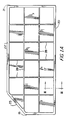
- the picking and storage container or bin of the present invention is entirely constructed of synthetic resin material, and consists of only four parts per bin, namely two mirror image side members 1 and 2, a folded blank 3, and a top 40.
- Each of the side members 1, 2 is a single one-piece homogenous molded synthetic resin part.
- the folded blank is a single one-piece homogenous molded synthetic resin part comprising a front wall 4, a bottom wall 5, a rear wall 6, and reduced thickness hinges, so called living-hinges, 7, 8.
- the top 4 is a single flat planar one-piece homogenous molded synthetic resin sheet, which may be stamped from flat sheets or otherwise cut from flat or rolled sheet material.
- connection between the folded blank and the side members is a snap type connection.
- the connection is only formed from portions of the side members and the folded blank, which portions are integrally formed in one piece on the side members 1, 2 and the folded blank 3 for connecting one side of the front wall 4, the bottom wall 5 and the rear wall 6 that is adjacent the side member 1 to the side member 1 and for connecting the other side of the front wall 4, the bottom wall 5 and rear wall 6 that is adjacent the side member 2 to the side member 2.
- the connection includes a U-shaped channel 9, particularly shown in Figure 3.
- the channel is made up of an inside leg portion 10, a web portion 11, a plurality of apertures 12 spaced along the web portion 11 and being of rectangular uniform shape, and outer leg 13.
- the outer leg 13 is provided with a plurality of hooks 14 that extend inwardly of the channel and form an inwardly facing abutment surface 15 and an outwardly facing cam surface 16, with respect to the inside of the channel.
- the inner leg 10 of the channel is connected integrally to the adjacent edge of a body portion 17 of the side member 1, and at such connection there is a cam surface 18 complementary to the cam surface 16 to form a wedge entrance to the channel.
- the hook 14 is completely coextensive, that is rectangularly and of identical dimensions, with the aperture 12, so that there are no undercut portions.
- the connection may be made entirely with a two part rigid mold, particularly two flat plates milled or otherwise formed without undercuts.
- This connection channel extends completely around the front edge 19, bottom edge 20 and rear edge 21 of the side member 1 for connection with the folded blank, and may extend additionally along the major portion 22 of the top edge that is parallel to the bottom edge 21 and along a minor portion 23 of the top edge that leads from a major portion 22 to the front edge 19.
- the channel along the major portion 22 and minor portion 23 is preferably of simpler construction, that is without the hook 14 having surfaces 15 and 16.
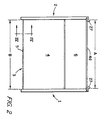
- each side member 1 may be a simple rectangular channel as shown in Figure 2 to extend horizontally as a groove inwardly opening and open towards the front for receiving therein the top 40, with sliding engagement, so that the top 40 may be assembled and removed from the front.
- the top 40 abuts against the overlapping rear wall 6 as shown in Figure 4. Since the front wall 4 extends to a lesser height than the rear wall 6, and the top extends only along the major portion 22, there is a slanted opening between minor edge portions 23 through which the contents of the container may be picked, or alternatively the top 40 may be completely removed for supply of additional contents or greater ease in picking; in such case the container would consist of three parts.
- the remainder of the connection is formed by a hook 24 extending from the side edge of each of the front wall 4, bottom 5, and rear wall 6.
- the hook 24 extends in the opposite direction to the extent of the hook 14, as shown in Figure 3, within the channel in the assembled position.
- the hook 24 has a planar abutment surface portion 25 coplanar with the abutment surface portion 15 of the hook 14 to form engaging portions that face each other and engage each other to prevent disassembly of the connection without the aid of tools.
- the hook 24 is further provided with a cam surface 26 complementary to the cam surface 16 of the hook 14, which cam surfaces 26 and 16 face away from each other, in the assembled position.
- the cam surfaces 16 and 26 wedgingly engage for spreading apart the channel during movement of the front wall, bottom wall 5 and rear wall 6 into the channel during assembly. During this assembly, the cam surface 18 further assists in such spreading apart of the channel and such assembly in a snap fashion.
- the top edge of the major portion 22 has an upstanding abutment flange 27 spaced inwardly from the remainder of the side wall 1, 2.
- the horizontal spacing A between outer portions of the abutment flanges 27, in the assembled position, being at least equal to the horizontal spacing B between inner portions of the channels of the two side members 1, 2, more particularly between the opposed hooks 14 as shown in Figure 2.
- This structure permits stacking of like containers upon each other, with or without tops, with the channels that are adjacent the bottom wall, as shown in Figure 3, receiving therebetween the flanges 27 of a lower container to prevent side to side shifting of the stacked containers or bins.
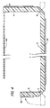
- the folded blank in its unstressed condition before assembly, would be in the dotted line position for the front wall 4 and rear wall 6, which would be coextensive with the bottom wall 5 as shown in Figure 4, with the reduced thickness hinge portions merely being parallel notches completely extending from one side to the other side of the blank at the two locations between adjacent walls.
- the hook 24 is merely an upstanding type flange, extending outwardly of the sheet material forming the remainder of the walls 4, 5, 6 in contrast to the reduced diameter portion that is a slot or channel extending inwardly of the sheets forming the walls 4, 5, 6. Therefore, it is seen that the folded blank may be molded from a mold consisting of only two flat plates with grooves to form the complementary structure.
- the side members 1 and 2 contain a plurality of reinforcing ribs 28 extending perpendicularly from the body portion of the side members and parallel to the legs 10, 13 of the channels.
- each side member is constructed only of a planar sheet main body portion and flanges extending parallel or perpendicular thereto, so that the side members may be each constructed of a plate mold consisting of only two flat plates milled with the appropriate flanges to produce the complementary structure.
- a computer program or the like used to mill the flat plates for one side member can easily be transposed or transformed to mill the mirror image to produce the mold for the other side member.
- the cost of the molds for a conventional plastic bin of this type would be approximately $120,000, as compared to $35,000 for the cost of the molds to produce the bin of the present invention.
- a further advantage of the present invention is that the bins may be shipped in knock down condition so that effectively air is not being shipped. That is, the shipping volume can be greatly reduced.
- sets of various width molded blanks may be employed and combined with the single size side members to produce different size bins, for example an eight inch wide bin or a 16 inch wide bin. Since there is no molding draft, that are no slanted sides to the molds for mold release for good space utilization. With no undercuts, the molds are easily produced by simple two dimensional milling of flat plates.
- the top may be provided with an extension to cover the minor edge portions 23 and completely cover the opening therebetween, which top extension would be connected to the illustrated top 4 with a hinge 7 and provided with some type of latch, for example a hook, for engagement with the front wall 4 to hold it in its closed position.
- Such top extension would be molded coplanar with the illustrated top 4, so that its normal unhooked position would be coextensive with the top 4 for easy picking of contents of the container.
- the parts are shipped in a flat, high cube utilization, condition.
- Field assembly will be achieved by bending the folded blank, at the living hinge lines, to form a somewhat U-shape. Sides will then be applied by a light pressure to engage the interlocks, or channel and hook portions.
- the bin or container is not intended to be knocked down once assembled. However, knocking down could be accomplished with tools.
- the bottom mold is molded in two widths in a common mold using inserts. These inserts can be designed to produce almost any width.
- Further features of the present invention include guides to prevent lateral shifting of stacked containers, which guides are specifically illustrated in the preferred embodiment as flanges 27. Stops prevent longitudinal shifting of stacked containers, particularly the rear wall could be extended above the top wall 4 and the channel along the bottom edge of each of the side members 1, 2 could be appropriately cut out for receiving the rear wall 6 of a lower container in the stacked condition.
- the top may be the illustrated plastic sheet material, or cardboard, or any appropriate material provided by the user, and easily shipped or easily obtained onsite for component protection. Even though the top is separate, and subject to loss, it can be easily replaced by any sheet material.
- a hopper front facilitates picking from the flow racks or shells containing a plurality of containers.
- the flat bottom facilitates conveying on conveyor rollers or wheel type conveyors.
- the container maximizes the use of flow rack area and optimizes open shelf spacing, because there is no draft, that is the side members front wall and rear wall extend vertically, and the top and bottom extend horizontally.
- the containers will be less expensive due to reduced molding cost, reduced shipping cost, reduced inventory since common side members may fit different size folded blanks to produce different size containers, and simple assembly.
Landscapes
- Engineering & Computer Science (AREA)
- Mechanical Engineering (AREA)
- Rigid Containers With Two Or More Constituent Elements (AREA)
- Containers Having Bodies Formed In One Piece (AREA)
- Cartons (AREA)
Claims (9)
- Conteneur de stockage en résine synthétique, comprenant
deux éléments latéraux séparés (1, 2) constitués chacun d'une pièce unique en résine synthétique moulée homogène en une seule pièce,
une paroi avant (4), une paroi de fond (5), une paroi arrière (6) et des moyens d'articulation d'épaisseur réduite (7, 8) reliés en une seule pièce auxdites parois pour former un élément pliant en résine synthétique moulée homogène en une seule pièce,
chaque élément latéral et chaque paroi possédant des moyens d'assemblage à engagement mutuel (14, 24) formés en une seule pièce sur l'élément latéral et les parois pour assembler un coté desdites parois avant, de fond et arrière à un des éléments latéraux et l'autre côté desdites parois avant, de fond et arrière à l'autre élément latéral,
caractérisé en ce que
les moyens d'assemblage comprennent un profilé en U (9) autour des bords avant (19), inférieur (20) et arrière (21) de chacun des éléments latéraux (1, 2), profilé contenant le bord adjacent desdites parois avant (4), de fond (5) et arrière (6), les éléments latéraux étant les images énantiomorphes l'un de l'autre;
et en ce que
les moyens d'assemblage comprennent des moyens d'accrochage (14) du profilé s'étendant à partir du bord libre (13) du profilé vers l'intérieur du profilé dans un sens, et des moyens (24) d'accrochage de paroi s'étendant dans le sens opposé à partir du bord de chacune desdites parois avant, de fond et latérale, dans le profilé, entre la partie formant l'âme (11) du profilé et les moyens d'accrochage du profilé. - Conteneur selon la revendication 1, caractérisé en ce que les moyens d'accrochage (14) du profilé et les moyens d'accrochage (24) des parois possèdent des parties d'engagement substantiellement coplanaires (15, 25) se trouvant en regard l'une de l'autre et des surfaces d'engagement complémentaires (16, 26) opposées l'une à l'autre, pour former un moyen s'engageant à la manière d'un coin pour ouvrir ledit profilé (9) durant le mouvement desdites parois avant (4), de fond (5) et arrière (6) dans ledit profilé pendant l'assemblage.
- Conteneur selon la revendication 1 ou 2, caractérisé en ce que les moyens d'accrochage du profilé consistent en une pluralité de crochets séparés espacés (14), et qu'une pluralité d'ouvertures (12) sont prévues, correspondant substantiellement en dimension et correspondant en nombre avec lesdits crochets, lesdites ouvertures étant ménagées dans l'âme (11) des profilés (9), pour faciliter le moulage desdits crochet dans un moule en deux pièces sans contre-dépouille.
- Conteneur selon l'une des revendications 1 à 3, caractérisé en ce que chacun desdits élements latéraux (1, 2) possède une partie de corps continue plane (17) et une pluralité de nervures de renforcement (28) dans toute ladite partie de corps, ces nervures s'étendant perpendiculairement vers l'extérieur à partir de ladite partie de corps, et le profilé s'étendant vers l'extérieur, à partir du périmètre de ladite partie de corps, sur une distance substantiellement égale aux nervures.
- Conteneur selon l'une des revendications 1 à 4, caractérisé en ce que la paroi avant (4) possède une hauteur substantiellement inférieure à celle de la paroi arrière (6), et que chaque élément latéral (1, 2) possède un bord supérieur s'étendant parallèlement à la paroi de fond (5) pour une première plus grande partie (22), puis obliquement vers le bas (23) en direction du bord supérieur de la paroi avant pour former un conteneur à prélèvement.
- Conteneur selon la revendication 5, caractérisé en ce que le bord supérieur de la grande partie (22) présente une rainure s'étendant horizontalement, s'ouvrant vers l'intérieur et ouverte vers l'avant; et qu'un couvercle (40) plan, rectangulaire, en résine synthétique s'introduit en coulissant dans ladite rainure et présente un bord arrière butant contre la paroi arrière (6).
- Conteneur selon les revendications 5 et 6, caractérisé en ce que le bord supérieur de la grande partie (22) des parois latérales (1, 2) présente un rebord de butée vertical (27) en retrait vers l'intérieur par rapport au reste de la paroi latérale (1, 2), l'espacement horizontal (A) entre les portions extérieures du rebord de butée étant au moins égal à l'espacement horizontal (B) entre les parties intérieures du profilé des moyens d'assemblage, de sorte que des conteneurs semblables, avec ou sans couvercles, peuvent être empilés l'un sur l'autre, les profilés (9) adjacents à ladite paroi de fond (5) recevant entre eux lesdits rebords pour empêcher les conteneurs empilés de glisser d'un côté à l'autre.
- Conteneur selon l'une des revendications 1 à 7, caractérisé par
une second élément identique audit premier élément pliant, excepté qu'il présente une plus grande largeur entre les côtés pour créer un jeu d'éléments interchangeables pour former sélectivement des conteneurs de dimensions différentes avec les éléments latéraux. - Conteneur selon l'une des revendications 1 à 8, caractérisé en ce que les moyens d'articulation d'épaisseur réduite (7, 8), dans leur état non contraint lorsque le conteneur n'est pas assemblé, maintiennent normalement la paroi avant (4), la paroi de fond (5) et la paroi arrière (6) dans un même plan, chaque paroi avant, de fond et arrière étant constitué d'une feuille rectangulaire plane d'épaisseur uniforme, à l'exception des moyens d'assemblage (14, 24), le moyen d'articulation d'épaisseur réduite étant une partie de liaison en forme de profilé entre deux feuilles adjacentes, et les moyens d'assemblage ne comportant pas de contre-dépouilles , pour le moulage dans un moule en deux parties, de sorte que l'élément pliant peut être moulé entièrement avec seulement deux plaques rigides configurées d'un moule à plaques.
Priority Applications (1)
| Application Number | Priority Date | Filing Date | Title |
|---|---|---|---|
| AT89119490T ATE84268T1 (de) | 1988-10-25 | 1989-10-20 | Zusammenschnappbarer lagerkasten. |
Applications Claiming Priority (2)
| Application Number | Priority Date | Filing Date | Title |
|---|---|---|---|
| US261756 | 1988-10-25 | ||
| US07/261,756 US4890740A (en) | 1988-10-25 | 1988-10-25 | Snap together picking container |
Publications (3)
| Publication Number | Publication Date |
|---|---|
| EP0366012A2 EP0366012A2 (fr) | 1990-05-02 |
| EP0366012A3 EP0366012A3 (fr) | 1991-01-23 |
| EP0366012B1 true EP0366012B1 (fr) | 1993-01-07 |
Family
ID=22994729
Family Applications (1)
| Application Number | Title | Priority Date | Filing Date |
|---|---|---|---|
| EP89119490A Expired - Lifetime EP0366012B1 (fr) | 1988-10-25 | 1989-10-20 | Caisse de stockage assemblée par encliquetage |
Country Status (5)
| Country | Link |
|---|---|
| US (1) | US4890740A (fr) |
| EP (1) | EP0366012B1 (fr) |
| AT (1) | ATE84268T1 (fr) |
| CA (1) | CA1331958C (fr) |
| DE (1) | DE68904288T2 (fr) |
Families Citing this family (25)
| Publication number | Priority date | Publication date | Assignee | Title |
|---|---|---|---|---|
| DE3904053A1 (de) * | 1989-02-10 | 1990-08-23 | Dillinger Juergen Dipl Finanzw | Baukastensystem |
| FR2693984B1 (fr) * | 1992-07-27 | 1994-11-04 | Yves Grand | Bac de rangement démontable. |
| CA2112426A1 (fr) * | 1993-01-08 | 1994-07-09 | Thomas Hunter | Unite de rangement modulaire |
| US5328048A (en) * | 1993-02-08 | 1994-07-12 | Otto Industries, Inc. | Tote box |
| JPH09173110A (ja) * | 1995-12-22 | 1997-07-08 | Ykk Corp | 裏面に連続リブを有する成形面ファスナー |
| US6305566B1 (en) | 2000-04-07 | 2001-10-23 | Nucon Corporation | Container for fragile articles |
| US20050189350A1 (en) * | 2002-10-22 | 2005-09-01 | Pactiv Corporation | Container assemblies with releasable locking feature |
| US20060000076A1 (en) * | 2002-10-22 | 2006-01-05 | Hayes Thomas J | Method of using a container assembly |
| US20060159807A1 (en) * | 2002-10-22 | 2006-07-20 | Hayes Thomas J | Container assemblies with releasable locking feature |
| US6886704B2 (en) * | 2002-10-22 | 2005-05-03 | Pactiv Corporation | Containers and container assemblies with releasable locking feature |
| US6966449B2 (en) * | 2003-01-02 | 2005-11-22 | The Little Tikes Company | Bulk box |
| WO2007016030A1 (fr) * | 2005-07-26 | 2007-02-08 | Pactiv Corporation | Ensembles récipients avec accessoire de verrouillage libérable |
| CA2621274A1 (fr) * | 2005-09-30 | 2007-04-12 | Pactiv Corporation | Ensemble contenant modulaire et presentation commerciale de contenant |
| US8083084B2 (en) * | 2007-09-06 | 2011-12-27 | Pwp Industries, Inc. | Invertible tray |
| CA2697419C (fr) | 2009-03-23 | 2014-03-18 | Kraft Foods Global Brands Llc | Appareil ayant trait a une ebauche monopiece et un emballage double coque en carton correspondant |
| US8616370B2 (en) | 2010-10-28 | 2013-12-31 | Arrows Up, Inc. | Bulk material shipping container |
| US8887914B2 (en) | 2010-10-28 | 2014-11-18 | Arrows Up, Inc. | Bulk material shipping container |
| EP2669207B1 (fr) * | 2012-05-29 | 2016-07-20 | Nefab Ab | Système de création d'un récipient et récipient correspondant |
| USD823645S1 (en) | 2016-06-06 | 2018-07-24 | Reynolds Consumer Products LLC | Plate |
| USD823644S1 (en) | 2016-06-06 | 2018-07-24 | Reynolds Consumer Products LLC | Plate |
| US10994954B2 (en) | 2016-06-30 | 2021-05-04 | Sandbox Enterprises, Llc | Bulk material shipping container unloader |
| CA2945454C (fr) | 2016-06-30 | 2023-11-07 | Arrows Up, Llc | Contenant d'expedition de materiau en vrac |
| USD818319S1 (en) | 2016-08-17 | 2018-05-22 | Reynolds Consumer Products LLC | Plate |
| US11661235B2 (en) | 2018-10-15 | 2023-05-30 | Sandbox Enterprises, Llc | Bulk material shipping container top wall assembly and bulk material shipping container having a top wall assembly |
| US10926940B2 (en) | 2018-11-20 | 2021-02-23 | Sandbox Enterprises, Llc | Bulk material shipping container |
Family Cites Families (24)
| Publication number | Priority date | Publication date | Assignee | Title |
|---|---|---|---|---|
| US2257536A (en) * | 1941-09-30 | roycroft | ||
| US628778A (en) * | 1898-07-19 | 1899-07-11 | Milo N Edwards | Packing-box. |
| US1326498A (en) * | 1917-01-12 | 1919-12-30 | Don H Hayden | Switch-box or outlet-box. |
| US1456385A (en) * | 1920-07-30 | 1923-05-22 | Alfred T Kvarnstrom | Fuse box |
| CH110208A (de) * | 1923-04-26 | 1925-05-16 | Bahlsens Keksfabrik Akt Ges H | Zerlegbarer Verpackungsbehälter aus Blech. |
| US2501980A (en) * | 1945-06-29 | 1950-03-28 | Dayton Pump & Mfg Co | Watering or feeding trough for animals |
| US2726004A (en) * | 1953-01-29 | 1955-12-06 | Philip H Mcleod | Single and multiple container bodies for foodstuff |
| US2744650A (en) * | 1953-08-17 | 1956-05-08 | Gibraltar Mfg Co Inc | Self-locking box structure |
| FR1169103A (fr) * | 1956-03-10 | 1958-12-23 | Metaldex | Jeu d'éléments pour la constitution d'un récipient métallique et récipient obtenu à l'aide de ces éléments |
| FR1289410A (fr) * | 1957-12-27 | 1962-04-06 | Wolf Geraete Gmbh | Caisse en tôle, notamment pour magasinage |
| CH404595A (de) * | 1963-08-29 | 1965-12-31 | Wander Ag Dr A | Satz von Teilen zum Anfertigen von Büchsen |
| US3273952A (en) * | 1964-07-14 | 1966-09-20 | H J Scheirich Company | Method of making furniture drawers or the like and article produced thereby |
| GB1261410A (en) * | 1968-06-19 | 1972-01-26 | Schaefer Gmbh Fritz | Improvements in or relating to stackable bins |
| US3675808A (en) * | 1970-06-26 | 1972-07-11 | Delbert L Brink | Knockdown foamed plastic shipping container |
| US3759412A (en) * | 1970-11-13 | 1973-09-18 | P Bush | Containers and their construction |
| US3878980A (en) * | 1971-10-29 | 1975-04-22 | Walton B Crane | Plastic reinforced produce container |
| JPS5241373Y2 (fr) * | 1972-06-10 | 1977-09-19 | ||
| ZA746647B (en) * | 1974-10-18 | 1976-05-26 | Plastipak Pty Ltd | Collapsible container |
| US3987924A (en) * | 1975-07-25 | 1976-10-26 | Uitz Mark O | Plastic container |
| GB2023543A (en) * | 1977-11-04 | 1980-01-03 | Fox C | Collapsible Stacking Container |
| US4402397A (en) * | 1980-11-28 | 1983-09-06 | Spence Jack T | Display case with castellated tongue and groove joints |
| US4445622A (en) * | 1982-07-09 | 1984-05-01 | Leonardo Sideri | Self-locking pilfer proof container |
| US4482074A (en) * | 1983-01-05 | 1984-11-13 | Lalley Donald P | Multipurpose container |
| US4625879A (en) * | 1985-10-31 | 1986-12-02 | Liu Clark W | User assembled desk top file |
-
1988
- 1988-10-25 US US07/261,756 patent/US4890740A/en not_active Expired - Fee Related
-
1989
- 1989-08-17 CA CA000608625A patent/CA1331958C/fr not_active Expired - Fee Related
- 1989-10-20 DE DE8989119490T patent/DE68904288T2/de not_active Expired - Fee Related
- 1989-10-20 EP EP89119490A patent/EP0366012B1/fr not_active Expired - Lifetime
- 1989-10-20 AT AT89119490T patent/ATE84268T1/de not_active IP Right Cessation
Also Published As
| Publication number | Publication date |
|---|---|
| DE68904288T2 (de) | 1993-05-27 |
| EP0366012A2 (fr) | 1990-05-02 |
| ATE84268T1 (de) | 1993-01-15 |
| CA1331958C (fr) | 1994-09-13 |
| US4890740A (en) | 1990-01-02 |
| EP0366012A3 (fr) | 1991-01-23 |
| DE68904288D1 (de) | 1993-02-18 |
Similar Documents
| Publication | Publication Date | Title |
|---|---|---|
| EP0366012B1 (fr) | Caisse de stockage assemblée par encliquetage | |
| US4887874A (en) | Knockdown drawers and bins | |
| US4243279A (en) | Stacking device | |
| US5515993A (en) | Hinged semi-rigid container having wall stiffening means | |
| US5582296A (en) | Stackable load bearing tray | |
| US6062388A (en) | Stackable bins | |
| US4798305A (en) | Adjustable shipping tray | |
| US20050051444A1 (en) | Utility case | |
| US7431171B2 (en) | Two piece container incorporating nesting characteristics and including interengageable hinge supports for upwardly supporting a lid upon a base | |
| CA1265478A (fr) | Boite de manutention | |
| NZ286886A (en) | Stackable tray; comprises a flat, rectangular floor panel and two side panels, structural details of panels | |
| GB2166116A (en) | Sidewall assembly for tote box | |
| US4448292A (en) | Knockdown suitcase | |
| US20180362212A1 (en) | Container with Dividers | |
| US5593037A (en) | Stackable bins | |
| GB2194133A (en) | Improved user assembled desk top file | |
| US4426056A (en) | Plate bracket for mounting a cassette box | |
| US2769679A (en) | File cabinets | |
| KR20240014459A (ko) | 플레이트를 위한 패키징 | |
| US4582248A (en) | Upwardly molded locking flange on carton | |
| JPH0740456U (ja) | 箱状ケース | |
| GB2571523A (en) | A combi box for the transport and storage of goods | |
| US20040129655A1 (en) | Stackable container, paper holder or the like | |
| US20230015782A1 (en) | Folding box | |
| CN214931516U (zh) | 一种边条及组装托盘 |
Legal Events
| Date | Code | Title | Description |
|---|---|---|---|
| PUAI | Public reference made under article 153(3) epc to a published international application that has entered the european phase |
Free format text: ORIGINAL CODE: 0009012 |
|
| AK | Designated contracting states |
Kind code of ref document: A2 Designated state(s): AT BE CH DE ES FR GB GR IT LI LU NL SE |
|
| PUAL | Search report despatched |
Free format text: ORIGINAL CODE: 0009013 |
|
| AK | Designated contracting states |
Kind code of ref document: A3 Designated state(s): AT BE CH DE ES FR GB GR IT LI LU NL SE |
|
| 17P | Request for examination filed |
Effective date: 19901228 |
|
| 17Q | First examination report despatched |
Effective date: 19911227 |
|
| GRAA | (expected) grant |
Free format text: ORIGINAL CODE: 0009210 |
|
| RAP1 | Party data changed (applicant data changed or rights of an application transferred) |
Owner name: BUCKHORN MATERIAL HANDLING GROUP, INC. |
|
| AK | Designated contracting states |
Kind code of ref document: B1 Designated state(s): AT BE CH DE ES FR GB GR IT LI LU NL SE |
|
| PG25 | Lapsed in a contracting state [announced via postgrant information from national office to epo] |
Ref country code: IT Free format text: LAPSE BECAUSE OF FAILURE TO SUBMIT A TRANSLATION OF THE DESCRIPTION OR TO PAY THE FEE WITHIN THE PRE;WARNING: LAPSES OF ITALIAN PATENTS WITH EFFECTIVE DATE BEFORE 2007 MAY HAVE OCCURRED AT ANY TIME BEFORE 2007. THE CORRECT EFFECTIVE DATE MAY BE DIFFERENT FROM THE ONE RECORDED.SCRIBED TIME-LIMIT Effective date: 19930107 Ref country code: GR Free format text: LAPSE BECAUSE OF FAILURE TO SUBMIT A TRANSLATION OF THE DESCRIPTION OR TO PAY THE FEE WITHIN THE PRESCRIBED TIME-LIMIT Effective date: 19930107 Ref country code: SE Effective date: 19930107 Ref country code: ES Free format text: THE PATENT HAS BEEN ANNULLED BY A DECISION OF A NATIONAL AUTHORITY Effective date: 19930107 Ref country code: NL Effective date: 19930107 |
|
| REF | Corresponds to: |
Ref document number: 84268 Country of ref document: AT Date of ref document: 19930115 Kind code of ref document: T |
|
| REF | Corresponds to: |
Ref document number: 68904288 Country of ref document: DE Date of ref document: 19930218 |
|
| ET | Fr: translation filed | ||
| NLV1 | Nl: lapsed or annulled due to failure to fulfill the requirements of art. 29p and 29m of the patents act | ||
| PGFP | Annual fee paid to national office [announced via postgrant information from national office to epo] |
Ref country code: CH Payment date: 19930913 Year of fee payment: 5 |
|
| PGFP | Annual fee paid to national office [announced via postgrant information from national office to epo] |
Ref country code: AT Payment date: 19930914 Year of fee payment: 5 |
|
| PGFP | Annual fee paid to national office [announced via postgrant information from national office to epo] |
Ref country code: BE Payment date: 19931013 Year of fee payment: 5 |
|
| PG25 | Lapsed in a contracting state [announced via postgrant information from national office to epo] |
Ref country code: LU Free format text: LAPSE BECAUSE OF NON-PAYMENT OF DUE FEES Effective date: 19931031 |
|
| PLBE | No opposition filed within time limit |
Free format text: ORIGINAL CODE: 0009261 |
|
| STAA | Information on the status of an ep patent application or granted ep patent |
Free format text: STATUS: NO OPPOSITION FILED WITHIN TIME LIMIT |
|
| 26N | No opposition filed | ||
| PGFP | Annual fee paid to national office [announced via postgrant information from national office to epo] |
Ref country code: DE Payment date: 19931230 Year of fee payment: 5 |
|
| PGFP | Annual fee paid to national office [announced via postgrant information from national office to epo] |
Ref country code: FR Payment date: 19940905 Year of fee payment: 6 |
|
| PG25 | Lapsed in a contracting state [announced via postgrant information from national office to epo] |
Ref country code: AT Effective date: 19941020 |
|
| PG25 | Lapsed in a contracting state [announced via postgrant information from national office to epo] |
Ref country code: CH Effective date: 19941031 Ref country code: LI Effective date: 19941031 Ref country code: BE Effective date: 19941031 |
|
| BERE | Be: lapsed |
Owner name: BUCKHORN MATERIAL HANDLING GROUP INC. Effective date: 19941031 |
|
| REG | Reference to a national code |
Ref country code: CH Ref legal event code: PL |
|
| PG25 | Lapsed in a contracting state [announced via postgrant information from national office to epo] |
Ref country code: DE Effective date: 19950701 |
|
| PG25 | Lapsed in a contracting state [announced via postgrant information from national office to epo] |
Ref country code: FR Effective date: 19960628 |
|
| REG | Reference to a national code |
Ref country code: FR Ref legal event code: ST |
|
| PGFP | Annual fee paid to national office [announced via postgrant information from national office to epo] |
Ref country code: GB Payment date: 20011030 Year of fee payment: 13 |
|
| REG | Reference to a national code |
Ref country code: GB Ref legal event code: IF02 |
|
| PG25 | Lapsed in a contracting state [announced via postgrant information from national office to epo] |
Ref country code: GB Free format text: LAPSE BECAUSE OF NON-PAYMENT OF DUE FEES Effective date: 20021020 |
|
| GBPC | Gb: european patent ceased through non-payment of renewal fee |
Effective date: 20021020 |