EP0365946A1 - Méthode de détermination des conditions de combustion dans un moteur à combustion interne à allumage par étincelle et dispositif de commande de ces conditions de combustion - Google Patents
Méthode de détermination des conditions de combustion dans un moteur à combustion interne à allumage par étincelle et dispositif de commande de ces conditions de combustion Download PDFInfo
- Publication number
- EP0365946A1 EP0365946A1 EP89119070A EP89119070A EP0365946A1 EP 0365946 A1 EP0365946 A1 EP 0365946A1 EP 89119070 A EP89119070 A EP 89119070A EP 89119070 A EP89119070 A EP 89119070A EP 0365946 A1 EP0365946 A1 EP 0365946A1
- Authority
- EP
- European Patent Office
- Prior art keywords
- condition
- combustion
- spark ignition
- combustion engine
- ignition internal
- Prior art date
- Legal status (The legal status is an assumption and is not a legal conclusion. Google has not performed a legal analysis and makes no representation as to the accuracy of the status listed.)
- Granted
Links
Images


Classifications
-
- F—MECHANICAL ENGINEERING; LIGHTING; HEATING; WEAPONS; BLASTING
- F02—COMBUSTION ENGINES; HOT-GAS OR COMBUSTION-PRODUCT ENGINE PLANTS
- F02D—CONTROLLING COMBUSTION ENGINES
- F02D29/00—Controlling engines, such controlling being peculiar to the devices driven thereby, the devices being other than parts or accessories essential to engine operation, e.g. controlling of engines by signals external thereto
-
- G—PHYSICS
- G01—MEASURING; TESTING
- G01L—MEASURING FORCE, STRESS, TORQUE, WORK, MECHANICAL POWER, MECHANICAL EFFICIENCY, OR FLUID PRESSURE
- G01L23/00—Devices or apparatus for measuring or indicating or recording rapid changes, such as oscillations, in the pressure of steam, gas, or liquid; Indicators for determining work or energy of steam, internal-combustion, or other fluid-pressure engines from the condition of the working fluid
- G01L23/22—Devices or apparatus for measuring or indicating or recording rapid changes, such as oscillations, in the pressure of steam, gas, or liquid; Indicators for determining work or energy of steam, internal-combustion, or other fluid-pressure engines from the condition of the working fluid for detecting or indicating knocks in internal-combustion engines; Units comprising pressure-sensitive members combined with ignitors for firing internal-combustion engines
- G01L23/221—Devices or apparatus for measuring or indicating or recording rapid changes, such as oscillations, in the pressure of steam, gas, or liquid; Indicators for determining work or energy of steam, internal-combustion, or other fluid-pressure engines from the condition of the working fluid for detecting or indicating knocks in internal-combustion engines; Units comprising pressure-sensitive members combined with ignitors for firing internal-combustion engines for detecting or indicating knocks in internal combustion engines
- G01L23/225—Devices or apparatus for measuring or indicating or recording rapid changes, such as oscillations, in the pressure of steam, gas, or liquid; Indicators for determining work or energy of steam, internal-combustion, or other fluid-pressure engines from the condition of the working fluid for detecting or indicating knocks in internal-combustion engines; Units comprising pressure-sensitive members combined with ignitors for firing internal-combustion engines for detecting or indicating knocks in internal combustion engines circuit arrangements therefor
-
- F—MECHANICAL ENGINEERING; LIGHTING; HEATING; WEAPONS; BLASTING
- F02—COMBUSTION ENGINES; HOT-GAS OR COMBUSTION-PRODUCT ENGINE PLANTS
- F02D—CONTROLLING COMBUSTION ENGINES
- F02D35/00—Controlling engines, dependent on conditions exterior or interior to engines, not otherwise provided for
- F02D35/02—Controlling engines, dependent on conditions exterior or interior to engines, not otherwise provided for on interior conditions
- F02D35/027—Controlling engines, dependent on conditions exterior or interior to engines, not otherwise provided for on interior conditions using knock sensors
-
- F—MECHANICAL ENGINEERING; LIGHTING; HEATING; WEAPONS; BLASTING
- F02—COMBUSTION ENGINES; HOT-GAS OR COMBUSTION-PRODUCT ENGINE PLANTS
- F02P—IGNITION, OTHER THAN COMPRESSION IGNITION, FOR INTERNAL-COMBUSTION ENGINES; TESTING OF IGNITION TIMING IN COMPRESSION-IGNITION ENGINES
- F02P5/00—Advancing or retarding ignition; Control therefor
- F02P5/04—Advancing or retarding ignition; Control therefor automatically, as a function of the working conditions of the engine or vehicle or of the atmospheric conditions
- F02P5/145—Advancing or retarding ignition; Control therefor automatically, as a function of the working conditions of the engine or vehicle or of the atmospheric conditions using electrical means
- F02P5/1455—Advancing or retarding ignition; Control therefor automatically, as a function of the working conditions of the engine or vehicle or of the atmospheric conditions using electrical means by using a second control of the closed loop type
-
- F—MECHANICAL ENGINEERING; LIGHTING; HEATING; WEAPONS; BLASTING
- F02—COMBUSTION ENGINES; HOT-GAS OR COMBUSTION-PRODUCT ENGINE PLANTS
- F02P—IGNITION, OTHER THAN COMPRESSION IGNITION, FOR INTERNAL-COMBUSTION ENGINES; TESTING OF IGNITION TIMING IN COMPRESSION-IGNITION ENGINES
- F02P5/00—Advancing or retarding ignition; Control therefor
- F02P5/04—Advancing or retarding ignition; Control therefor automatically, as a function of the working conditions of the engine or vehicle or of the atmospheric conditions
- F02P5/145—Advancing or retarding ignition; Control therefor automatically, as a function of the working conditions of the engine or vehicle or of the atmospheric conditions using electrical means
- F02P5/15—Digital data processing
- F02P5/152—Digital data processing dependent on pinking
- F02P5/1527—Digital data processing dependent on pinking with means allowing burning of two or more fuels, e.g. super or normal, premium or regular
-
- F—MECHANICAL ENGINEERING; LIGHTING; HEATING; WEAPONS; BLASTING
- F02—COMBUSTION ENGINES; HOT-GAS OR COMBUSTION-PRODUCT ENGINE PLANTS
- F02B—INTERNAL-COMBUSTION PISTON ENGINES; COMBUSTION ENGINES IN GENERAL
- F02B1/00—Engines characterised by fuel-air mixture compression
- F02B1/02—Engines characterised by fuel-air mixture compression with positive ignition
- F02B1/04—Engines characterised by fuel-air mixture compression with positive ignition with fuel-air mixture admission into cylinder
-
- F—MECHANICAL ENGINEERING; LIGHTING; HEATING; WEAPONS; BLASTING
- F02—COMBUSTION ENGINES; HOT-GAS OR COMBUSTION-PRODUCT ENGINE PLANTS
- F02B—INTERNAL-COMBUSTION PISTON ENGINES; COMBUSTION ENGINES IN GENERAL
- F02B75/00—Other engines
- F02B75/02—Engines characterised by their cycles, e.g. six-stroke
- F02B2075/022—Engines characterised by their cycles, e.g. six-stroke having less than six strokes per cycle
- F02B2075/027—Engines characterised by their cycles, e.g. six-stroke having less than six strokes per cycle four
-
- F—MECHANICAL ENGINEERING; LIGHTING; HEATING; WEAPONS; BLASTING
- F02—COMBUSTION ENGINES; HOT-GAS OR COMBUSTION-PRODUCT ENGINE PLANTS
- F02D—CONTROLLING COMBUSTION ENGINES
- F02D35/00—Controlling engines, dependent on conditions exterior or interior to engines, not otherwise provided for
- F02D35/02—Controlling engines, dependent on conditions exterior or interior to engines, not otherwise provided for on interior conditions
- F02D35/023—Controlling engines, dependent on conditions exterior or interior to engines, not otherwise provided for on interior conditions by determining the cylinder pressure
-
- Y—GENERAL TAGGING OF NEW TECHNOLOGICAL DEVELOPMENTS; GENERAL TAGGING OF CROSS-SECTIONAL TECHNOLOGIES SPANNING OVER SEVERAL SECTIONS OF THE IPC; TECHNICAL SUBJECTS COVERED BY FORMER USPC CROSS-REFERENCE ART COLLECTIONS [XRACs] AND DIGESTS
- Y02—TECHNOLOGIES OR APPLICATIONS FOR MITIGATION OR ADAPTATION AGAINST CLIMATE CHANGE
- Y02T—CLIMATE CHANGE MITIGATION TECHNOLOGIES RELATED TO TRANSPORTATION
- Y02T10/00—Road transport of goods or passengers
- Y02T10/10—Internal combustion engine [ICE] based vehicles
- Y02T10/40—Engine management systems
Definitions
- This invention relates to a method for determining the combustion condition that is capable of determining rapidly and exactly the combustion condition in a spark ignition internal combustion engine by detecting physical phenomena directly relating to the combustion, and to a combustion condition control device that is capable of controlling the combustion condition in the engine rapidly and correctly.
- the ignition timing for the spark ignition internal engine (hereinafter simply referred to as "engine") to generate a maximal torque is in the vicinity of knocking conditions, the ignition timing condition for the maximal torque tends to have a high probability of knocking.
- the engine has been provided with a cylinder internal pressure sensor or an acceleration sensor to detect vibrations in the cylinder or accelerations generated in the engine that occur in association with knocking, thereby evaluating the operation conditions or ignition timing, or correcting the ignition timing during operation to suppress occurrence of knocking while obtaining a maximal torque from the engine.
- Another object of the present invention is to provide a combustion control device which is capable of optimally controlling the physical condition in a spark ignition internal combustion engine to prevent occurrence of knocking.
- the inventors of the present invention have conducted intensive studies and various experiments to develop a method which is capable of positively preventing knocking while obtaining a maximal torque from an engine, and found specific phenomena in the vicinity of knocking conditions.
- the combustion rate increases, and, as shown in Fig. 1 (a), change in heat evolution rate becomes sharper in the vicinity of the knocking condition as indicated by dot-bar lines than in the normal combustion as indicated by broken lines. This is considered as due to the fact as what follows.
- Chemical reactions of normal combustion proceed in three step: a first step peroxide reaction, a second step cold flame reaction (or a formaldehyde reaction), and a third step hot flame reaction.
- the third step involves an explosive reaction
- the first and second steps are pre-reactions in which hydrocarbons in the fuel dissociate into formaldehyde and high-energy free radicals such as OH and H0 2 .
- the first and second pre-reactions take place in the uncombustion area of the combustion chamber at pressure and temperature of immediately before those of self-ignition, where large amounts of high-energy free radicals exist, which is considered to be a more chemically activated state than normal state. Therefore, it is considered that when the flame face reaches the area. the third step hot flame reaction immediately takes place without a delay required for the pre-reactions. resulting in increased flame velocity and heat evolution rate.
- G is an amount of combustion gas.
- A is a thermal equivalent of work.
- P is an internal pressure of combustion chamber, and dV is a change in combustion chamber volume
- the amount of heat evolution dQ is given as In Equation (1), du is an increase in internal energy which, where Cv is a constant volume specific neat, dT is a change in temperature, R is the gas constant, and k is a ratio of specific heat, is given as
- a first method for determining combustion condition comprising a first step for detecting physical values of combustion varying in association with combustion in a combustion chamber of a spark ignition internal combustion engine, a second step for calculating the rate of heat evolution from the physical values of combustion, and a third step for determining the combustion condition from changes in the falling area of the heat evolution rate.
- a second method for determining combustion condition comprising a first step for detecting physical values varying in association with combustion in a combustion chamber of a spark ignition internal combustion engine, a second step for obtaining interrelated physical values interrelated with heat evolution rate from the results of detection in the first step, and a third step for determining the combustion condition from changes in the interrelated physical values dictating the falling of heat evolution rate.
- combustion condition control device comprising combustion physical value detecting means for detecting combustion physical values varying in association with combustion in a combustion chamber of a spark ignition internal combustion engine, calculation means for calculating the rate of heat evolution from the combustion physical values, parameter setting means operating in response to the output of the calculation means to set combustion control operation parameters for the spark ignition internal combustion engine according to changes in the falling area of heat evolution rate, and adjusting means for adjusting the combustion condition in the spark ignition internal combustion engine according to the combustion control operation parameters set by the parameter setting means.
- combustion condition control device comprising combustion physical value detecting means for detecting combustion physical values varying in association with combustion in a combustion chamber of a spark ignition internal combustion engine, calculation means for calculating interrelated physical values interrelated with heat evolution rate from the combustion physical values parameter setting means operating in response to the output of the calculation means to set combustion control operation parameters for the spark ignition internal combustion engine according to changes in the interrelated physical values dictating the falling of heat evolution rate, and adjusting means for adjusting the combustion condition in the spark ignition internal combustion engine according to the combustion control operation parameters set by the parameter setting means.
- the above physical values of combustion include the cylinder internal pressure P and line spectra obtained by separating the light of flame emitted when the fuel burns, all of which relate to the calorific value.
- Equation (5) above it is also possible, without strictly calculating the rate of heat evolution dO/de, to calculate the rate of change in the cylinder internal pressure dP/d ⁇ , which varies in proportion to the rate of heat evolution dQ/de, and evaluate the combustion condition from changes in condition in the falling area of the rate of change in the cylinder internal pressure dP/de.
- Fig .1 is a graph showing the relationship between crank angle position e and heat evolution rate dQ/de of a spark ignition internal combustion engine (hereinafter referred to as "engine").
- engine heat evolution rate
- dQ/d ⁇ with sufficiently small tendency to knocking as indicated by broken lines
- the heat evolution rate in a condition immediately before knocking (knocking does not occur) as indicated by dot-bar lines and that in a knocking condition as indicated by solid lines individually involve substantial changes in the mode of falling.
- the rate of change in heat evolution rate dQ/d ⁇ in the falling area of the heat evolution rate dQ/d ⁇ from the peak value of the heat evolution rate dQ/d8 to the completion of combustion can be determined in comparison with a certain reference to determine, for example, whether or not it is a condition immediately before knocking (knock does not occur), enabling evaluation of the setting of the operation conditions such as ignition timing, air/fuel ratio, and air-boosting pressure.
- the falling area of the heat evolution rate dQ/d ⁇ that is, the crank angle position from the peak value of the heat evolution rate dQ/de to the completion of combustion, is detected as a falling time
- crank angle position 6 is detected by crank, angle detecting means 11, and cylinder internal pressure P is detected by cylinder internal pressure detecting means 12.
- Heat evolution rate calculation means 13 calculates the rate of heat evolution dQ/d ⁇ using Formula (4) above.
- the heat evolution rate dQ/d ⁇ is calculated, it is preferable to cut off high-frequency vibration components due to knocking and the like by a filter.
- the pressure diagram always contains high-frequency vibration components and, by cutting off such vibration components, the change in the heat evolution rate dQ/de is simplified as shown in Fig.1.
- a cut-off filter it is effective to use a Fourier series type filter when real-time operation is required, such as in on-board knocking control, or a filter using a direct FET method or that using a spline function method for the case where real-time operation is not important, such as for bench test measuring instruments.
- is calculated by falling time calculation means 14 from the crank angle position ⁇ 100 at which the heat evolution rate dQ/d ⁇ exhibits a peak value and the crank angle position 9 o at the completion of combustion, previously measured.
- the inventive method when used with bench test measuring instruments, it is preferable to cut off large peaks caused by knocking. This is because, if the peak is simply taken from changes in heat evolution rate dQ/de while knocking occurs, a peak due to knocking often is the highest one, but the peak value that is to be detected in the inventive method should be the peak during normal combustion. To cut off such spurious peaks, it is effective to use a pattern matching method in which waveform patterns of normal combustion are memorized, and peaks which are largely out of the patterns are cut off, or a method in which, since knocking peak always occurs after the peak generated by normal combustion, the later one of two peaks generated in one combustion cycle is ignored. However, since even if the knocking peak is mis-judged as to be the peak of heat evolution rate dQ/de, the determination result from the falling time or gradient indicates a knocking-prone condition, it may be unnecessary to discriminate the knocking peak.
- is compared by determination means 15, for example, with a preset reference value to determine whether or not it is abnormal combustion, and the determination signal is outputted to various combustion adjusting means for the case of on-board knocking control, or to display means and recording means for the case of bench test measuring instruments.
- on-board control for example, when the calculated falling time
- EGR exhaust gas recirculation
- in addition to the above-described comparison with the reference value, it may alternatively be determined from the ratio of the calculate falling time to the peak value of the heat evolution rate dQ/d ⁇ or to a time
- in stable combustion area may alternatively be average values obtained by processing a plurality of data.
- the determination level of the above ratios may be mapped values which vary with operation conditions.
- Figs.4 and 5 relate to a second embodiment of the present invention.
- the portions where changes in relative heat evolution rate dQ/d ⁇ between immediately after the peak of heat evolution rate dQ/d ⁇ and immediately before the completion of combustion are cut off, the area, for example, from a crank angle position e 90 for 90% of the peak value of heat evolution rate dQ/d ⁇ to a crank angle position ⁇ 10 for 10% of the peak value is set as a detection area, and the falling time
- Figs.6 and 7 relate to a third embodiment of the present invention.
- a late portion of the falling area that is, for example, the portion from a crank angle position ⁇ 50 for 50% of the peak value of heat evolution rate dQ/de to a crank angle position 6 0 of the completion of combustion is set as a detection area, and the falling time
- Figs.8 and 9 relate to a fourth embodiment of the present invention.
- a portion in the vicinity of the completion of combustion is cut off, a portion of the falling area, that is, for example, the portion from a crank angle position e 50 for 50% of the peak value of heat evolution rate dQ/d ⁇ to a crank angle position ⁇ 10 for 10% of the peak value of heat evolution dQ/de is set as a detection area, and the falling time
- combustion condition is evaluated according to the time required for the change from a first value of heat evolution rate dQ/d ⁇ to a second value smaller than the first value, predetermined in the falling area.
- the rate of change in cylinder internal pressure dP/de which is in a proportional relation to the heat evolution rate dQ/d ⁇ , may be calculated to evaluate the combustion condition from the time required for the change from a first value of cylinder internal pressure changing rate dP/d ⁇ predetermined within the falling area of the cylinder internal pressure changing rate dP/de to a second value which is smaller than the first value.
- time is discussed as the period of time
- Figs.10 and 11 relate to a fifth embodiment of the present invention.
- a maximal value of negative gradient in the falling area of heat evolution rate dQ/d ⁇ is detected from a rate of change d 2 Q/d ⁇ 2 , and the detected value is compared with a preset reference value for evaluation as described above.
- the evaluation of the detected value may alternatively made from the ratio of the rate of change in heat evolution rate d 2 Q/d B 2 to its positive maximal value.
- heat evolution rate changing rate calculation means 19 a rate of change in heat evolution rate d 2 Q/de 2 is approximated to by the second derivative of cylinder internal pressure P (Fig. 10).
- the rate of change in heat evolution rate d 2 Q/de 2 can be approximated to by the second derivative of cylinder internal pressure P.
- FIG.12 and 13 An example of device and technique to obtain the second derivative of cylinder internal pressure P is shown in Figs.12 and 13.
- a cylinder internal pressure P is sampled at (i)th time by the cylinder internal pressure detecting means 12 using a sufficiently short sampling period, and a crank angle position e is detected by the crank angle detecting means 11.
- cylinder internal pressure changing rate calculation means 20 reads cylinder internal pressure P i ., sampled immediately before the (i)th time from a memory 21, and the rate of change per unit angle is calculated from both P i-1 and cylinder internal pressure P i at the (i)th time to obtain dP/de.
- the cylinder internal pressure P i at the (i)th time and its rate of change dP i /d ⁇ are stored in the memory 21.
- cylinder internal pressure second-derivative calculation means 22 reads dP i-1 /d ⁇ at the (i-1)th time from the memory 21, and the rate of change per unit angle is calculated from both dP i-1 /d ⁇ and dP i /d ⁇ for the (i)th time to obtain d z P i /d ⁇ 2.
- the d 2 Pi/d ⁇ 2 is stored in the memory 21.
- the rate of change in heat evolution rate d 2 Q/de 2 in only the falling area of heat evolution rate dQ/de is calculated in the heat evolution rate changing rate calculation means 19, which can reduce the calculation time.
- the minimal value of the heat evolution rate dQ/de is out of the detection area, it cannot be compared with the peak value of the heat evolution rate dQ/de.
- Figs.14 and 15 relate to a sixth embodiment of the present invention.
- This embodiment is a development of the modification example in the fifth embodiment, in which the detection area for the rate of change in heat evolution rate d 2 Q/d ⁇ 2 is reduced to the latter half of the falling area of the heat evolution rate dQ/de to enhance the calculation speed.
- heat evolution rate changing rate calculation means 19 in addition to the detection of the peak value of heat evolution rate dQ/de and crank angle position ⁇ 100 at that time, the value of heat evolution rate dQ/d ⁇ of 50% (or its vicinity) of its peak value is calculated. and crank angle position 0 5 o for 50% of the peak value of heat evolution rate dQ/de after that crank angle position e 100 and crank angle position ⁇ 0 for the completion of combustion are detected. Then, the rate of change in heat evolution rate dQ/d ⁇ in the detection area of the latter half of the falling area of heat evolution rate dQ/d ⁇ is calculated to detect its minimal value.
- Other configurations and functions are same as those in the first embodiment.
- the rate of change in heat evolution rate d 2 Q / do 2 may be strictly determined using Formula (6) above in accordance with the purpose of control and/or the capacity of the heat evolution rate changing rate calculation means 19, or, as can be seen from Formula (7) above, the rate of change in heat evolution rate d 2 Q/d ⁇ 2 may be replaced with the second derivative of cylinder internal pressure P (falling gradient of the rate of change in cylinder internal pressure dP / de).
- numeral 23 indicates a 4-cycle 4-cylinder gasoline engine for a vehicle and a combustion chamber 24 of each cylinder is provided with a cylinder internal pressure sensor 26 as combustion physical value detecting means in addition to an ignition plug 25.
- the cylinder internal pressure sensor 26 integrates a piezoelectric device, which converts the cylinder internal pressure pressure P to an electrical charge which is outputted.
- a flywheel 27 is provided adjacently with a crank angle sensor 28, which outputs a signal every time the crank shaft of the engine 23 makes a unit angle of rotation (e.g. 1 0 ).
- the ignition plug 25 is connected to an electronic control unit (hereinafter referred to as "ECU") 31 via an ignition coil 29 and a power transistor 30, and is driven and controlled by the ECU 31.
- the cylinder internal pressure sensor 26 is connected to the ECU 31 via a charge amplifier 32, a multiplexer (MPX) 33, and a low-pass filter (LPF) 34, and the crank angle sensor 28 is connected directly to the ECU 31, respectively outputting cylinder internal pressure P and crank angle position 9 to the ECU 31.
- the ECU 31 is connected with a number of devices related to the air-intake system, the exhaust gas cleaning system and the like, for integrated control over the engine 23 but, for simplicity, description of these devices is omitted.
- a sensor (hereinafter referred to as "G sensor") to detect vibration acceleration in the vicinity of the combustion chamber 24 may be provided to determine the combustion condition from combustion condition information of the engine 23 obtained by the above combustion condition determination methods and knocking information obtained by the G sensor. Control over an engine using this method will be described later.
- the cylinder internal pressure detection signal detected by the cylinder internal pressure detecting means 12 is supplied to forecasting type combustion determination means 35 via the low-pass filter 34, and to backup combustion determination means 37 via a bandpass (high-pass) filter 36.
- Internal pressure P of each cylinder which is detected in association with a change in crank angle position 6 in the explosion stroke, contains high-frequency components as shown in graph (a) of Fig.17, which are removed by the low-pass filter 34 to obtain a signal with no high-frequency components as shown in graph (b) of Fig.17.
- the bandpass filter 36 allows only frequencies that are characteristic of abnormal combustion in the cylinder to pass. Vibrations generated by knocking are air columnar vibrations, and have a frequency specific to the engine. Therefore, the frequency band that passes through the bandpass filter 36 is set to an appropriate value (e.g., 6 KHz) according to the specific engine and the combustion phenomenon to be detected.
- an appropriate value e.g. 6 KHz
- Detection of abnormal combustion such as knocking or the like by the backup combustion determination means 37 is carried out by a conventional method known in the art, for example, by reading the voltage level of the cylinder internal pressure signal at every generation of high-frequency sampling signal, counting the number of times of the voltage level exceeding a reference value and, from the count value, detecting the frequency of abnormal combustion occurrence, that is, the knocking magnitude. When the occurrence frequency or the knocking magnitude exceeds a predetermined value, it is determined as occurrence of knocking.
- the combustion condition determination method using the forecasting type combustion determination means 35 has been described above using Figs.1 to 15.
- the low-pass filter 34 and the bandpass filter 36 may be those which use frequency analysis to separate low-frequency components and high-frequency components, respectively.
- Effective types of filter in this case include, as described above, a Fourier series type filter when real-time operation is required such as in on-board knocking control, or or a filter using a direct FET method or that using a spline function method for the case where real-time operation is not important, such as for bench test measuring instruments.
- combustion control operation parameters to control knocking such as ignition timing are controlled as follows.
- a select signal is supplied from the backup combustion determination means 37 to select means 38, and the select means 38 is switched to first retard angle signal generation means 39.
- a retard angle signal ⁇ S R1 generated by the signal generation means 39 is supplied to an ignition timing control device (not shown).
- the retard angle signal AS R1 in this case may be one which is to retard the ignition timing by a constant value, or one which is to set the timing to a value in response to the knocking magnitude.
- the select signal is not supplied to the select means 38, and the select means 38 is switched to the select means 40 side.
- an advance angle signal AS A or a retard angle signal AS R2 is outputted through the select means 40 and 39 in accordance with the knocking allowance detected by the forecasting type combustion determination means 35.
- the forecasting type combustion determination means 35 calculates the knocking allowance, which is compared with a reference value (target knocking allowance) to determine whether or not the current ignition timing is leading relative to the target knocking allowance.
- a retard angle signal AS R2 when it is leading, or an advance angle signal ⁇ S A , when it is lagging, is supplied to the select means 40.
- the select means 40 is connected with advance angle signal generation means 41 and second retard angle signal generation means 42, which are selected by the select means 40.
- advance angle signal AS A is outputted from the forecasting type combustion determination means 35
- the select means 40 is switched to the advance angle signal ⁇ S A generation means 41 side, and advance angle signal AS A is outputted through the select means 40 and the select means 38.
- retard angle signal AS R2 is outputted from the forecasting type combustion determination means 35
- the select means 40 is switched to the second retard angle signal generation means 42 side, and retard angle signal ⁇ S R2 is outputted through the select means 40 and the select means 38.
- the ignition timing control device (not shown) is to electronically advance or retard the ignition timing in response to the retard angle signal ⁇ S R1 , ⁇ S R2 or the advance angle signal ⁇ S A outputted from the select means 38, and even when knocking does not actually occurs, the ignition timing is advanced or retarded in accordance with the knocking allowance determined by the forecasting type combustion determination means 35 to prevent knocking, thereby controlling the ignition timing to an optimal value that enables the highest output of the engine.
- detection sensitivity of the forecasting type combustion determination means 35 may become deteriorated or unworkable. If there is such an area where the detection becomes deteriorated or impossible, the backup combustion determination means 37 is selected for the area so that the combustion condition is detected by the backup combustion determination means 37 alone.
- combustion condition is determined by the forecasting type combustion determination means 35 and. when it becomes impossible to determine the combustion condition by the forecasting type combustion determination means 35, the impossibility is detected from an engine operation condition, for example, from the engine rotational speed Ne, and the backup combustion determination means 37 is selected to determine the combustion condition by the the backup combustion determination means 37.
- engine rotational speed Ne is detected by the crank angle detecting means 11, and when the detected engine rotational speed Ne is lower than a predetermine determination value Nr (e.g.. 4,000 rpm), select means 43 is switched to the forecasting type combustion determination means 35 side by a select signal supplied from the crack angle detecting means 11 to the select means 43.
- a predetermine determination value Nr e.g. 4,000 rpm
- select means 43 is switched to the forecasting type combustion determination means 35 side by a select signal supplied from the crack angle detecting means 11 to the select means 43.
- Nr e.g. 4,000 rpm
- the select means 43 is switched to the backup combustion determination means 37 side by a select signal supplied from the crank angle detecting means 11 to the select means 43.
- a combustion determination signal determined by the backup combustion determination means 37 is supplied to the recording control means 44 via the select means 15.
- whether or not the detection by the forecasting type combustion determination means 35 is impossible is determined as follows. Referring to Figs.22 and 23, an abnormal combustion detection rate "a" by the forecasting type combustion determination means 35 and an abnormal combustion detection rate "/3" by the backup combustion determination means 37 are respectively calculated, and when the ratio ⁇ i ⁇ exceeds a predetermined determination value H, the backup combustion determination means 37 is selected to determine the combustion condition by the backup combustion determination means 37.
- the select means 43 is always supplied with combustion determination signals from both the forecasting type combustion determination means 35 and the backup combustion determination means 37. Furthermore, the combustion determination signal of the forecasting type combustion determination means 35 is also supplied to first abnormal combustion rate calculation means 45.
- the abnormal combustion rate calculation means 45 counts the number of abnormal combustion detections by the forecasting type combustion determination means 35 in a predetermine period of time or in a period for the engine to make a predetermined number of turns, and calculates abnormal combustion rate a.
- the calculated abnormal combustion rate a is supplied to comparator means 46.
- the combustion determination signal of the backup combustion determination means 37 is also supplied to second abnormal combustion rate calculation means 47, which counts the number of abnormal combustion detections by the backup combustion determination means 35 in a predetermined period of time or in a period for a predetermined number of turns to calculate the abnormal combustion rate p.
- the calculated abnormal combustion rate is supplied to the comparator means 46.
- the comparator means 46 compares the ratio ⁇ 3/a obtained from the abnormal combustion rates a and ⁇ supplied by the two abnormal combustion rate calculation means 45 and 47 with a predetermined reference value H, and when the ratio ⁇ i ⁇ is smaller than the predetermined reference value H, the forecasting type combustion determination means 35 is determined to be good in the combustion condition determination sensitivity, and a select signal is supplied to the select means 43 to select it to the forecasting type combustion determination means 35 side.
- the combustion determination signal determined by the forecasting type combustion determination means 35 is supplied to the recording control means 44 via the select means 43.
- the forecasting type combustion determination means 35 is determined to be deteriorated in the combustion condition determination sensitivity or impossible to determine, and the select means 43 is switched to the backup combustion determination means 37 side by a select signal supplied from the comparator means 46 to the select means 43.
- the combustion determination signal determined by the backup combustion determination means 37 is supplied to the recording control means 44 via the select means 43.
- the combustion determination signal is used, for example, in a knock control system of an engine, knocking control by an optimal operation parameter setting device or the like, and recording means for an abnormal combustion measuring device, and these devices are supplied with the combustion determination signal to perform recording or knocking control.
- the knock control system may be an ignition timing control device for controlling the ignition timing, an air fuel ratio control device to control the amount of fuel injection to the engine, an air-boost pressure control device to control opening of a waste gate value of an engine equipped with an air-booster, a control device to control opening of an EGR valve of an engine equipped with an EGR device, a compression ratio control device, or a compression ratio control device to control compression ratio of an engine.
- the operation area in which the engine is operated is detected from engine rotational speed and intake negative pressure and, when the engine operation enters a predetermined operation area, the backup combustion determination means 37 is selected.
- the vibration acceleration in the vicinity of the combustion chamber may be detected in place of the high-frequency components of the cylinder internal pressure P, and the detection result is used.
- a combustion chamber 24 of each cylinder of an engine 23 is provided with a cylinder internal pressure sensor 26 as combustion physical value detecting means in addition to an ignition plug 25.
- a cylinder block 48 is provided with a G sensor 49 as vibration acceleration detecting means.
- the cylinder internal pressure sensor 26 and the G sensor 49 both integrate piezoelectric devices, which respectively convert the cylinder internal pressure P and the vibration acceleration in the cylinder block 48 into electrical charges that are outputted.
- a flywheel 27 is provided adjacently with a crank angle sensor 28, which outputs a signal every time the crank shaft of the engine 23 makes a unit angle of rotation (e.g., 1°).
- the ignition plug 25 is connected to an ECU 31 via an ignition coil 29 and a power transistor 30, and is driven and controlled by the ECU 31.
- the cylinder internal pressure sensor 26 is connected to the ECU 31 via an amplifier 32, a multiplexer 33, and a low-pass filter 34, the G sensor 49 is connected to the ECU 31 via an amplifier 50, and the crank angle sensor 28 is connected directly to the ECU 31, respectively outputting cylinder internal pressure P and crank angle position 8 to the ECU 31.
- the ECU 31 is connected with a number of devices related to the intake system, the exhaust gas cleaning system and the like, for integrated control over the engine 23 but, for simplicity, description of these devices is omitted.
- Fig.25 is a block diagram of the tenth embodiment.
- select means 51 is inputted with operation condition information such as engine rotational speed Ne from operation condition detecting means 52.
- operation condition information such as engine rotational speed Ne from operation condition detecting means 52.
- the select means 51 selects first combustion condition determination means 53 or second combustion condition determination means 54.
- Output signal of the combustion condition determination means (53 or 54) selected is inputted to combustion control means 55 to control combustion of the engine 23.
- the first combustion condition determination means 53 is represented, for example, by one which is shown in the block diagram in Fig.2.
- knocking condition is monitored by the G sensor 49.
- the crank angle sensor 28 separately from the calculation of the rate of change in cylinder internal pressure dP / de by calculation means 20, acts as the operation condition detecting means 52 to detect engine rotational speed Ne, and transmits the signal to the select means 51.
- the select means 51 compares the detected engine rotational speed Ne in M1 with a predetermined determination value Nr (e.g., 4,000 rpm) in M2, and when Ne ⁇ Nr, selects the first combustion condition determination means 51, that is, a forecasting type combustion condition determination device in M3, or when Ne > Nr, selects the second combustion condition determination device 54, that is, the knocking detection device using the G sensor 49 in M4.
- Nr e.g., 4,000 rpm
- Combustion control flow when the select means 51 selects the first combustion condition determination means 53 is represented, for example, by the flow chart in Fig.3.
- the combustion control means 55 calculates the excessive advance angle ⁇ S Ri , and retards the ignition timing by AS RI . Or, when there is an allowance to knocking, that is, when normal combustion is determined, the combustion control means 55 calculates the retard angle OS A , relative to the optimal ignition timing, and advances the ignition timing by ⁇ S A1 .
- the ⁇ S R1 or ⁇ S A1 may be set to a sufficiently small value, and ignition timing be gradually retarded or advanced at every cycle of combustion.
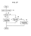
- Fig.27 is a combustion control flow chart when the select means 51 selects the second combustion condition determination means 54.
- the G sensor 49 converts vibration acceleration in the cylinder block 48 to an electrical charge, which is transmitted to the ECU 31.
- the ECU 31 determines whether or not there is knocking condition from the strength of the vibration acceleration signal, and when knocking is determined, in M7, the combustion control means 55 unconditionally retards the ignition timing by ⁇ S R2, or when knocking is not determined, in M8, whether or not the current ignition timing is a predetermined maximal advance angle value is determined.
- the current ignition timing is the maximal advance angle value, it is returned as is, or when the ignition timing is lagging from the maximal advance angle value, the ignition timing is advanced by AS A2 in M9.
- combustion control means 55 performs combustion control by advancing or retarding the ignition timing, however, the above-described other combustion control means may alternatively be driven.
- both the forecasting type and vibration acceleration detection type means are used to determine the combustion condition, compared to the tenth embodiment, in which the first combustion condition determination means 53 makes combustion condition determination according to the falling condition of the rate of change in cylinder internal pressure dP.'de that is, a forecasting type combustion condition determination is made.
- Fig.28 is a block diagram of the eleventh embodiment.
- first combustion condition determination means 53 is supplied with signals from cylinder internal pressure changing rate calculation means 20 and G sensor 49.
- Other configurations are same as those used in the tenth embodiment shown in Fig.25.
- Fig.29 is a flow chart of the first combustion condition determination means 53 used in the eleventh embodiment.
- the 6 sensor 49 converts vibration acceleration in the cylinder block 48 to an electrical charge and transmits it to the ECU 31.
- the ECU 31 determines whether or not there is a knocking condition from the strength of the vibration acceleration signal and, when knocking is determined, the combustion control means 55 unconditionally retards the ignition timing by AS R2 in M12. If knocking is not determined, determination in M13 to M18 is made for combustion condition based on the falling time of the rate of change in cylinder internal pressure, and combustion control of M19 and M20, or M21 and M22, is made according to the determination result.
- Fig.30 is a block diagram of a twelfth embodiment of the present invention.
- First combustion condition determination means 53 and second combustion condition determination means 54 are individually same as those used in the tenth embodiment and description thereof is omitted here.
- Combustion condition determination signal from the first combustion condition determination means 53 is inputted to first abnormal combustion rate calculation means 45 which calculates a first abnormal combustion rate ⁇ .
- Combustion condition determination signal from the second combustion condition determination means 54 is inputted to a second abnormal combustion rate calculation means 47 which calculates a second abnormal combustion rate 13.
- the first and second abnormal combustion rates a and are compared in comparator means 46, and the comparison result is inputted to select means 51. Then, according to the comparison result, the select means 51 selects the first combustion condition determination means 53 or the second combustion condition determination means 54. Output signal of the selected combustion condition determination means (53 or 54) is inputted to the combustion control means 55 to control combustion of the engine 23.
- Fig.31 is a flow chart for the selection of the combustion condition determination means 53 or 54.
- output signal of cylinder internal pressure changing rate calculation means 20 is read by the first abnormal combustion rate calculation means 45.
- output signal of the G sensor 49 is read by the second abnormal combustion rate calculation means 47.
- a first abnormal combustion rate a per a predetermined number of samplings is calculated by the first abnormal combustion rate calculation means 45. Specifically, a falling time, for example,
- abnormal combustion rate per a predetermined number of samplings is calculated by the second abnormal combustion rate calculation means 47, as shown in M26. Specifically, the rate of the G sensor 49 output signal greater than a predetermined value, that is, the knocking rate, in the past 20 times of combustion at that time is calculated.
- the comparator means 46 calculates the ratio ⁇ i ⁇ of the second abnormal combustion rate to the first abnormal combustion rate ⁇ , compares the ratio with a predetermined determination value H in M27, and outputs the comparison result to the select means 51.
- the select means 51 selects the first combustion condition determination means 53 in M28 when ⁇ , ⁇ H, or selects the second combustion condition determination means 54 in M29 when ⁇ / ⁇ > H.
- the combustion control flow chart when the first combustion condition determination means 53 is selected and that when the second combustion condition determination means 54 is selected are same as those in the tenth embodiment, for example, as shown in Fi.3 and Fig. 27, and description thereof is omitted.
- which combustion condition determination means is selected is determined from actual abnormal combustion rate detected by forecasting type and vibration acceleration detection type combustion condition determination means, even if the engine is rotating at a high speed, when the forecasting type combustion condition determination device can detect a condition immediately before knocking, better combustion control is possible without selecting the vibration acceleration type combustion condition determination means.
- a thirteenth embodiment of the present invention is a control method for a multi-octane fuel compatible engine.
- the control method for the engine shown in the thirteenth embodiment uses operation condition setting means 56, fuel condition determination means 57, octane number determination means 58, ignition timing map select means 59, and engine operation adjusting means 60 as shown in Fig.32.
- the operation condition setting means 56 is to previously set the ignition timing and air / fuel ratio during idling operation after starting the engine to optimal values for the determination of octane number of the fuel.
- the conditions for a 2,000-cc displacement engine are to increase the engine rotational speed Ne to approximately 1,200 rpm and to give an ignition advance angle (e.g. 25°) corresponding to full load. With these operation conditions, the following determination is performed. To increase the engine rotational speed Ne, an idle control valve is opened to increase the intake.
- the crank angle position 8 from the peak value of the heat evolution rate dQ/de to the completion of combustion is detected by combustion condition determination means 57 as a falling time
- crank angle position e is detected by crank angle detecting means 11, and cylinder internal pressure P as a combustion physical value is detected by cylinder internal pressure detecting means 12.
- heat evolution rate calculating means 13 calculates the rate of heat evolution dQ/de.
- is calculated by falling time calculating means 14 from the crank angle position ⁇ 100 at which the heat evolution rate dQ/de exhibits a peak value and the crank angle position eo at the completion of combustion, previously measured.
- is calculated, which is compared with a predetermined reference value to determine the combustion condition.
- Octane number determination means 58 determines the octane number from the falling time
- Premium gasoline and regular gasoline with different octane numbers differ in heat evolution rate dQ/de relative to crank angle position e. As shown in Figs.35 to 37 showing the condition of a 2,000-cc displacement engine operating at a rotational speed of 2,000 rpm under full load, this difference is not so conspicuous when the ignition timing is lagging as shown in Fig.
- the low-octane regular gasoline shows a greater gradient of falling than the high-octane premium gasoline, and the regular gasoline has a shorter combustion time.
- a plurality of fuels with different octane numbers are combusted under the same condition as above to determine test data of falling time
- the octane number may alternatively be determined from the ratio of the falling time to the peak value of heat evolution rate dQ/de or from the ratio of the falling to the time
- in the stable combustion area may be average values obtained by processing a plurality of data.
- the ignition timing map select means 59 is to select a most suitable ignition timing map having operation parameters most suitable for the fuel used, according to the determination result of the octane number determination means 58.
- a most suitable ignition timing map having operation parameters most suitable for the fuel used, according to the determination result of the octane number determination means 58.
- three-dimensional maps for ignition timing relative to engine rotational speed and load (intake pressure or the like) are set for individual octane numbers, which are stored in the electronic control unit. From these, the ignition timing map select means 59 selects an ignition timing map which is equivalent or close to the determined octane number.
- .an ignition timing map may also be selected by interpolation of two maps. Instead of, or in addition to. selecting an ignition timing map, a map for air/fuel ratio or air-boost pressure or compression ratio may be selected, according to the octane number.
- the operation adjusting means 60 is to operate the engine according to the ignition timing map selected.
- an ignition key is turned to start the engine.
- operation conditions for the octane number determination are set by the operation condition setting means 56 during the idling operation, and the engine is operated under these conditions for a predetermined period of time. If otherwise, such operation conditions are not set, and an ignition timing map for the previously determined octane number is selected.
- the combustion condition determination means 57 determines whether changing condition of the heat evolution rate dQ/de is calculated from the change in cylinder internal pressure P, and the falling time is determined by the combustion condition determination means 57.
- the octane number of the fuel used is determined by the octane number determination means 58.
- the ignition timing map select means 59 selects an appropriate map from a plurality of ignition timing maps previously stored in the electronic control unit. The engine is operated by the operation adjusting means 60 according to the operation parameters of the ignition timing map selected.
- a switch for detecting fuel replenishment is provided at the filler neck or the filler cap, and operation of the flow chart shown in Fig.38 may be triggered by the output signal of the switch. Or, an ignition timing map for low-octane fuel or medium-octane fuel may be selected until the idling operation of the engine is detected.
- a fourteenth embodiment of the present invention is a control method for a multi-octane fuel compatible engine. Referring to Fig.39, this method uses combustion condition determination means 57, operation parameter setting means 61, and operation adjusting means 60.
- the combustion condition determination means 57 determines the rate of change in heat evolution rate d 2 Q/d ⁇ 2 in the falling area of the heat evolution rate dQ/de from the peak value of the heat evolution rate dQ/de to the completion of combustion in comparison with a certain reference to determine, for example, whether or not it is a condition immediately before knocking (knock does not occur), enabling evaluation of the setting of the operation parameters such as ignition timing, air/fuel ratio, and air-boost pressure.
- the falling area of the heat evolution rate dQ/d ⁇ for example, the crank angle from the peak value of the heat evolution rate dQ/de to the completion of combustion, is detected as a falling time
- as a knock allowance K is calculated by knock allowance determination means 62 from the crank angle position ⁇ 100 for the peak value of heat evolution rate dQ/d ⁇ and the crank angle position ⁇ 0 for completion of combustion, both previously detected.
- the operation parameter setting means 61 will now be described.
- the operation parameter setting means 61 as shown in Fig.39, has retard value calculation means 63, interpolation factor determination means 64, ignition timing calculation means 65, and first and second ignition timing storage units 66 and 67.
- the retard value calculation means 63 compares the knock allowance K (falling time, for example,
- the interpolation factor determination means 64 determines an interpolation factor C for interpolating individual ignition timing maps stored in the first and second ignition timing storage units 66 and 67 according to the retard value ⁇ S R calculated.
- the ignition timing calculation means 65 interpolates ignition timing data S x and Sy of the individual ignition timing maps outputted from the first and second ignition timing storage units 66 and 67 with the calculated retard value ⁇ S R and interpolation factor C to calculate ignition timing data So which is most suitable for the fuel used.
- the first and second ignition timing storage units 66 and 67 are storage units to store the ignition timing map for regular gasoline and the ignition timing map for premium gasoline, respectively.
- the operation parameter setting means 61 sets ignition timing data as operation parameters which are most suitable for the fuel used.
- the operation adjusting means 60 is to operate the engine according to the operation parameters set by the operation parameter setting means 61.
- the retard value calculation means 63 first compares the knock allowance K calculated with the first knock allowance reference value K r1 , If K ⁇ K r1 , a retard angle correction value ⁇ S R1 is added to the previously set retard value ⁇ S R to obtain a new retard value ⁇ S R + ⁇ S R1 . If K ⁇ K r1 , the knock allowance K and the second knock allowance reference value K r2 are compared. If K > K r2 , the previous retard value ⁇ S R is subtracted by an advance angle correction value ⁇ S A to obtain a new retard value ⁇ SR - AS A . If K r1 ⁇ K ⁇ K r2 , the previous retard value ⁇ S R remains unchanged.
- the interpolation factor determination means 64 compares the thus set retard value ⁇ S R and a second reference retard value ⁇ S Rr2 . If ⁇ S R > ⁇ S Rr2 , an addition value ⁇ C 2 is added to the previously set interpolation factor C to obtain a new interpolation factor C + ⁇ C 2 . If ⁇ S R ⁇ S Rr2 , the current retard value ⁇ S R is compared with a first reference retard values ⁇ S Rr1 . If ⁇ S R ⁇ ⁇ S Rr1 , the previous interpolation factor C is subtracted by a reduction value ⁇ C 1 to obtain a new interpolation factor C - ⁇ C1. If ⁇ S Rr1 ⁇ ⁇ S R ⁇ S Rr2 , the previous interpolation factor remains unchanged.
- interpolation factor C The value of interpolation factor C is clipped within 0 ⁇ C 1.
- the ignition timing calculation means 65 interpolates the ignition timing data S x and Sy for premium gasoline and regular gasoline stored in the first and second ignition timing storage units 66 and 67 with the interpolation factor C to determine basic ignition timing data Sr, to which are added an ignition timing correction value AS and the retard value ⁇ S R according to the operation condition of the engine to set ignition timing data So as an operation parameter.
- the operation adjusting means 60 operates the engine according to the thus set ignition timing data So.
- the engine can be operated with operation parameters most suitable for the octane number of the fuel used, thereby improving the engine output and drivability, with improved mileage.
- a fifteenth embodiment of the present invention is a control method for a multi-octane fuel compatible engine. Referring to Fig.41. this method uses combustion condition determination means 57, operation parameter setting means 61, and operation adjusting means 60, and the operation parameter setting means 61 has setting area determination means 68.
- the setting area determination means 68 determines whether the steady operation condition other than small-load operation and rapid acceleration has continued for a predetermined period of time.
- the setting area determination means 68 determines whether or not the inputted engine rotational speed Ne and load are within the setting area for steady operation of the engine. If these are out of the area, operation is continued with the current interpolation factor C. If within the area, whether or not the operation condition has continued for a predetermined period of time is determined.
- Fig.43 is a block diagram of a sixteenth embodiment of the control method for a multi-octane fuel compatible engine according to the present invention
- Fig.44 is its flow chart.
- This embodiment of the control method for the multi-octane fuel compatible engine uses combustion condition determination means 57, operation parameter setting means 61, and operation adjusting means 60, and the operation parameter setting means 61 has air / fuel ratio calculation means 69 to calculate air / fuel ratio as an operation parameter in addition to the ignition timing.
- the air/fuel ratio calculation means 69 interpolates airifuel ratio data D x and Dy of the individual air/fuel ratio maps outputted from first and second air/fuel ratio storage units 70 and 71 with the calculated retard value ⁇ S R and interpolation factor C, to calculate air/fuel ratio data Do which is most suitable for the fuel used.
- the interpolation factor C is determined, and the air'fuel ratio calculation means 69 interpolates the aiduel ratio data D x and Dy for premium gasoline and regular gasoline outputted from the first and second air/fuel ratio storage units 70 and 71 with the interpolation factor C to determine basic air/fuel ratio data D R , to which are added an ignition timing correction value AD and the product of the retard value ⁇ S R and an interpolation factor E according to the operation condition of the engine to set air/fuel ratio data Do as an operation parameter.
- operation of the engine is controlled using the ignition timing data So calculated by the ignition timing calculation means 65 and the air/fuel ratio data Do calculated by the air/fuel ration calculation means 69.
- operation of the engine is controlled using the two operation parameters, ignition timing and air/fuel ratio, but other operation parameters include air-boost pressure and compression ratio, which may also be used for the control over the engine operation.
- Fig.45 is a block diagram of a seventeenth embodiment of the control method for a multi-octane fuel compatible engine according to the present invention
- Fig.46 is its flow chart.
- operation parameter setting means 61 has retard value calculation means 63, setting area determination means 68, ignition timing map select means 59, and ignition timing calculation means 65.
- the setting area determination means 68 determines whether or not the engine rotational speed Ne and load are within the setting area for steady operation condition and whether or not a predetermine period of time is elapsed. If any one of the conditions is not met, the premium fuel ignition timing data Sy is inputted from the premium fuel ignition timing map, and the most suitable ignition timing data So is calculated.
- the retard value ⁇ S R is compared with a reference retard value ⁇ S Rr3 ⁇ If ⁇ S R > ⁇ S Rr3 , the retard value ⁇ S R is phase-shifted by the difference (S x - Sy) between the individual ignition timing data S x and Sy inputted from the regular and premium fuel ignition timing maps, the regular fuel ignition timing data S x is inputted from the regular fuel ignition timing map, and the phase-shifted retard value and an ignition timing correction value AS according to the operation condition of the engine are added to determine the ignition timing data So.
- the operation adjusting means 60 operates the engine according to the ignition timing data So as a newly-set operation parameter.
- Fig.47 is a block diagram of an eighteenth embodiment of the control method according to the present invention when applied to a multi-octane fuel compatible engine
- Fig.48 is its flow chart.
- This embodiment of the control method for the multi-octane fuel compatible engine uses operation condition setting means 56, and operation parameter setting means 61 comprising load detecting means 72, setting area determination means 68, fuel determination means 73, operation parameter select means 74, and knock allowance reflecting means 75.
- the operation condition setting means 56 calculates ignition timing data S x or Sy suitable for regular or premium fuel from maps or the like to set operation condition suitable for the fuel.
- the load detecting means 72 is to detect load condition of the engine.
- the setting area determination means 68 is to determine, as in the previous embodiment, when the engine is operated with premium fuel, whether or not the knock allowance K is within an engine load area (e.g., heavy-load area) as a setting area where the allowance is smaller than the first knock allowance reference value K r1 .
- an engine load area e.g., heavy-load area
- the fuel determination means 73 determines that, when the engine is operated with the premium fuel ignition timing data Sy and the setting area determination means 68 determines out of the above setting area, the fuel is regular fuel.
- the operation parameter select means 74 selects the ignition timing map as an operation parameter.
- the knock allowance reflecting means 75 advances or retards the ignition timing according to the knock allowance K.
- Fuel replenishment is first checked. If no fuel replenishment has been made, the regular fuel flag is checked, and the ignition timing data Sx of the regular fuel ignition timing map is inputted. When the regular fuel flag is not set and fuel replenishment is made, the regular fuel flag is reset, and the ignition timing data Sy of the premium fuel ignition timing map is inputted. Thus, the operation condition is set by the operation condition setting means 56. When the premium fuel ignition timing map is set, the combustion condition determination means 57 calculates the knock allowance K, which is compared with the first and second knock allowance reference values K r1 and K r2 .
- K > K r2 there is a sufficient allowance to knocking, and the ignition timing data is re-inputted without changing the ignition timing map. If K r1 ⁇ K ⁇ K r2 , it is considered to be good combustion condition, and the ignition timing is not changed. If K ⁇ K r1 , which indicates occurrence of knocking or immediately before knocking, the engine rotational speed Ne and load are detected and inputted by the load detecting means 72, and the engine is operated with the premium fuel by the setting area determination means 68 to determine whether or not the knock allowance K is within the setting area where K ⁇ K r1 .
- the knock allowance K is out of the setting area, which determines the the fuel used to be regular fuel
- the regular fuel flag is set
- the regular fuel ignition timing map is selected by the operation parameter select means 74
- the ignition timing data S x is inputted.
- the setting area determination means 68 When within the setting area is determined by the setting area determination means 68, which indicates that the fuel used is premium fuel, the ignition timing map is unchanged, and the ignition timing is retarded or advanced by the knock allowance reflecting means 75.
- Fig.49 is a flow chart of a nineteenth embodiment of the control method according to the present invention when applied to a multi-octane fuel compatible engine.
- This embodiment of the control method for a multi-octane fuel compatible engine uses control of an air-boost pressure map to operate the engine, in addition to the ignition timing map as an operation parameter as used in the eighteenth embodiment described above. After checking for fuel replenishment, the premium fuel air-boost pressure is set and the ignition timing data Sy of the premium fuel ignition timing map is inputted to determine the combustion condition, thereby setting the ignition timing and air-boost pressure that are most suitable for the fuel used.
- Other configurations and functions are same as those used in the above eighteenth embodiment, and description thereof is omitted.
- Fig.50 is a flow chart of a twentieth embodiment of the control method according to the present invention when applied to a multi-octane fuel compatible engine.
- the combustion condition is determined using the premium fuel ignition timing map
- this embodiment uses a test ignition timing map previously prepared, and determination is made using the map.
- the test ignition timing map has ignition timing data suitable for a test octane number fuel having an octane number between those of premium fuel and regular fuel.
- Combustion condition is determined using the test ignition timing data S T to calculate the knock allowance K. If the knock allowance K is within the setting area and K > K, 2 , the fuel is determined as premium fuel, or if K ⁇ K rt , the fuel is determined as regular fuel, according to which the ignition timing map is selected.
- the setting area is such an area that when the ignition timing is set to the test data, the engine is prone to knocking with regular gasoline, but is not knocking-prone with premium gasoline, for example, a medium- load area. Subsequent processing is same as that in the above eighteenth embodiment, and description thereof is omitted. With the test ignition timing data S T given, when the engine is operated out of the setting area, knock control is made according to the knock allowance detected, as in the case after the determination of the fuel used.
- Fig.51 is a flow chart of a twenty-first embodiment of the control method according to the present invention when applied to a multi-octane fuel compatible engine.
- This embodiment of the control method uses control over another parameter, for example, air-boost pressure, in addition to the determination of fuel used according to the test ignition timing map as used in the twentieth embodiment described above.
- the ignition timing and air-boost pressure as operation parameters are controlled to operate the engine.
- other parameters such as air / fuel ratio and or compression ratio may be controlled. Configurations and functions of this embodiment are same as those in the twentieth embodiment, and description thereof is omitted.
- Fig.52 is a block diagram of a twenty-second embodiment of the control method according to the present invention when applied to a multi-octane fuel compatible engine
- Fig.53 is its flow chart. Referring to Fig.52, this embodiment of the control method for a multi-octane fuel compatible engine compares the ignition timing data So after the ignition timing is advanced within the test area with the select reference ignition timing data S' r to determine the fuel used.
- the premium fuel flag is reset, and the ignition timing data S x of the regular fuel ignition timing map is inputted.
- Engine rotational speed Ne and load are detected and, when these are within the setting area of steady operation, operation condition changing means 76 subtracts the ignition timing data by an advance angle correction value. Then, the combustion condition is determined and, when the knock allowance K is smaller than the reference value K r1 , the fuel determination means 73 compares this ignition timing data 0 T with the select reference ignition timing data So.
- the select reference ignition timing data S r has a value which is smaller than the ignition timing which gives K ⁇ K r1 when the engine is operated with regular fuel and is greater than the ignition timing which gives K ⁇ K r1 when the engine is operated with a high-octane fuel. Therefore, the fuel determination means 73 determines that the fuel used is regular fuel when So > S/ and that the fuel used is premium fuel when So ⁇ S' r . After that, as in the foregoing embodiment, the engine is operated with the operation parameters set by the operation parameter select means 74 and the knock allowance reflecting means 75.
- Fig.54 is a flow chart of a twenty-third embodiment of the control method according to the present invention when applied to a multi-octane fuel compatible engine.
- This embodiment of the control method for a multi-octane fuel compatible engine uses control of a air-boost pressure map to operate the engine, in addition to the ignition timing map as an operation parameter as used in the eighteenth embodiment described above.
- the ignition timing data So after advancing is compared with the select reference ignition timing S r ' to determine the fuel used
- this embodiment of the control method for a multi-octane fuel compatible engine compares the output torque after advancing the ignition timing with a select reference torque to determine the fuel used.
- the ignition timing is advanced, and the combustion condition is determined. If K ⁇ K r1 , the current torque To is detected and inputted, and the output torque To is compared with a select reference torque T r .
- the select reference torque T has a value which is greater than the torque generated when the engine is operated with regular fuel and gives K ⁇ K r1 and smaller than the torque generated when the engine is operated with high-octane fuel and gives K ⁇ K r1 . Therefore, the fuel determination means 37 determines that the fuel used is regular fuel when To ⁇ T, and that the fuel used is premium fuel when To > T,.
- the fuel used is determined from the output torque. However, it may alternatively be determined using air-boost pressure, air fuel ratio, or compression ratio.
- a combustion condition control device is configured using the combustion condition determination method according to the present invention, it is also effective to incorporate a logic to prevent the ignition timing from being advanced beyond an ignition timing for the maximal torque (MBT: Minimum spark advance for Best Torque) when the ignition timing is advanced according to the falling condition of heat evolution rate dQ/de.
- MBT Minimum spark advance for Best Torque
- an ignition timing correction value AS is calculated based on the difference between the knock allowance K and a reference knock allowance, basic ignition timing data S, corresponding to the current load and the engine rotational speed Ne is read from a basic ignition timing map which is previously set for load and the engine rotational speed Ne, and ignition timing data S n for the next ignition timing is calculated from these ignition timing correction value AS and basic ignition timing S, and the value inputted into the address S m of the RAM.
- the above-obtained ignition timing correction value AS is added to the value inputted into the address S m , and the result is inputted to the address S m .
- the cumulative result of ignition timing correction value AS is stored in the address S m .
- MBT data So is read from the MBT map previously set by the load and the engine rotational speed Ne, the MBT data So is compared with the previously calculated ignition timing data S n for the next ignition timing and, if the ignition timing data S n for the next ignition is same as or retarding from the MBT data S D , the next ignition timing data S n is adopted as is as the next ignition timing. If the next ignition timing data S n is advancing from the MBT data So, the MBT data So is replaced for the next ignition timing.
- Execution of the above flow is repeatedly conducted by interruption of timer signals or pulse signals from the crank angle sensor to determine, for example, next ignition timing data S n for individual ignitions or for a predetermined period of time.
- a twenty-fifth embodiment of the present invention shown in Figs.56 to 62 relates to the determination of octane number of the fuel used, as also described in the thirteenth embodiment.
- a cylinder head 77 of an engine 23 is provided with an ignition plug 25 and a cylinder internal pressure sensor 26, ends of which are located in a combustion chamber surrounded by the cylinder head 77, a cylinder block 78, and a piston 78 sliding in the cylinder block 78.
- a valve stem 79 slidably penetrating the cylinder head 77 is disposed an intake cam shaft 83 formed integrally with a cam 82 to open and close an intake passage 81 through an intake valve 80.
- an exhaust passage (not shown) and an exhaust valve are provided in the cylinder head 77, and above these are disposed an exhaust cam shaft to drive the exhaust valve and the like.
- a crank angle sensor 28 which, however, may alternatively be mounted at the exhaust cam shaft side or connected to a distributor or the like which is connected to the ignition plug 25.
- the crank angle sensor 28 and the cylinder internal pressure sensor 26 are connected with a cumulative calculation means 84, which receives a pressure signal from the cylinder internal pressure sensor 26 and a crank angle position signal from the crank angle sensor 28 to calculate in real-time changes in the heat evolution rate dQ/d ⁇ according to the capability of the cumulative calculation means 84.
- a filter using a direct FFT method or one using a spline function method is effective.
- time is determined from a crank angle position 8 50 which exhibits 50% the heat evolution rate dQ/de at a crank angle position ⁇ 100 for the first peak value of heat evolution rate dQ/d ⁇ to a crank angle position ⁇ 10 for 10% the value for the crank angle position ⁇ 100, where the difference in octane number of fuel appears most conspicuously.
- crank angle position ⁇ 100 for the peak value of heat evolution rate dQ/d ⁇ is determined from crank angle position 8 and cylinder internal pressure P, and a falling time from the crank angle position 8 50 so exhibiting 50% the heat evolution rate dQ/d ⁇ to the crank angle position ⁇ 10 exhibiting 10% the heat evolution rate dQ/d ⁇ is calculated.
- large peaks caused by knocking are necessary to be cut off. This is because, if a peak is taken simply from changes in heat evolution rate dQ/d ⁇ during knocking, a peak due to knocking often will be the highest peak, but it is a peak during normal combustion that is to be detected in this embodiment.
- 40 combustion strokes are sampled, and the falling times
- may be arranged in the increasing order and plotted into a curve as shown in Figs.58 to 60, or may be averaged.
- calculation may be made from falling times from ⁇ 100 to 8 0 . It is preferable to use operation condition for the engine 23 which clearly exhibits the difference between regular gasoline and premium gasoline, for example, with an ignition timing advance angle of 25 BTDC.
- Figs.58 to 60 show the result of data for heat evolution rate dQ / de under the operation condition shown in the thirteenth embodiment, in which lengths of time from 50% to 10% of the first peak of heat evolution value dQ/d ⁇ to 10% are converted into crank angles of the engine 23, and data of 40 measurements are arranged and plotted in the increasing value.
- the mark • indicates occurrence of knocking which occurs when the ignition timing is set to 25 BTDC.
- the ignition timing for regular gasoline, the period of the final area of combustion stroke is considerably reduced from that of normal combustion under knocking condition or in the vicinity of knocking condition, whereas almost no change in the period is noted for premium gasoline. Therefore, for the determination of octane number, it is preferable to set the ignition timing, for example, to 25° BTDC.
- a storage means 85 connected to an octane number determination means 58 together with the cumulative calculation means 24, addition results for individual standard fuels are stored, which are previously obtained by combusting a plurality of standard fuels having known octane numbers under the same condition for the sample and adding the calculation results of falling time for 40 measurements according to the procedure shown in Fig.57.
- the octane number determination means 58 as shown in Fig.61 showing flow chart thereof, compares the addition results of sample to be measured for octane number with the addition results of the standard fuels stored in the storage means 85 to determine the octane number of the sample. Therefore, the more types of standard fuels stored in the storage means 85 give the higher reliability of the results of measurement. If no standard fuel which has the same addition results as those of the sample is found, octane number is determined by interpolation or the like.
- the ignition timing advance angle is maintained at a constant value.
- Fig.62 showing the flow chart of a twenty-sixth embodiment of the present invention
- it is possible to determine the octane number by operating the engine using a plurality of fuel types while advancing the ignition timing, storing ignition timings at which the average values of falling time of 40 measurements are individually less than predetermined reference values, operating the engine using the sample while advancing the ignition timing to determine the ignition timing at which the average value of falling time of 40 measurements is less than the reference value, and comparing it with the ignition timing for the standard fuels.
- the initial value of ignition timing is one at which no difference occurs in falling time between the sample and the standard fuels.
- the ignition timing map preparation device mainly comprises an engine 23 for testing purpose, an operation adjusting means 60 for controlling the operation condition of the engine 23, and map preparation calculation means 86 for processing data obtained by operation of the engine to prepare a map.
- a combustion chamber 24 of each cylinder of the engine 23 is provided, in addition to an ignition plug 25, with a cylinder internal pressure sensor 26 as cylinder internal pressure detecting means.
- the cylinder internal pressure sensor 26 incorporates a piezoelectric device to convert the cylinder internal pressure P to an electrical output.
- a flywheel 27 is provided adjacently with a crank angle sensor 28, and an intake passage 81 and an exhaust passage 87 are respectively mounted with an intake pressure sensor 88 for detecting intake pressure and an 0 2 sensor 89 for detecting oxygen concentration of exhaust gas.
- a crank shaft 90 is connected with a dynamometer 91 for giving the engine 23 a load and measuring the output and shaft torque.
- the operation adjusting means 60 drives the ignition plug 25 through an ignition driver 92 and the like and drives a fuel injection valve and a throttle valve (both not shown) to control the fuel injection rate and intake rate.
- map preparation calculation means 86 the signal from the cylinder internal sensor 26 together with the signal from the crank angle sensor 28 is inputted to a heat evolution rate calculation means 13 and, after being processed, is inputted into a memory 21.
- the signal from the crank angle sensor 28 is inputted into the memory 21 through an engine rotational speed calculation means 93, and signals from the O2 sensor 89 or an exhaust gas analyzer (not shown) and the like are amplified by an amplifier (AMP) 50 and inputted to the memory 21. Signals from other sensors and devices are inputted as they are into the memory 21.
- the map preparation calculation means 86 is connected, in addition to the above sensors and devices, with detecting means (not shown) for detecting atmospheric conditions such as atmospheric pressure and atmospheric temperature, and signals from these detecting means are also inputted into the memory 21.
- map preparation calculation means 86 are further provided a data bank 94, an ignition timing calculation means 65, and a map preparation means 95.
- Data inputted from the heat evolution rate calculation means 13 to the memory 21 is inputted into the data bank 94 via the ignition timing calculation means 65.
- Other signals and data in the memory 21 are also rearranged and inputted into the data bank 94.
- map preparation means 95 an ignition timing map is prepared using various data in the data bank 94.
- the map preparation calculation means 86 sets engine rotational speed Ne to the lowest (idling) speed, load L to zero load, air/fuel ratio D to the richest value, and ignition timing S to the maximal retard value, which are inputted to the operation adjusting means 60.
- the actual engine rotational speed Ne is measured by the crank angle sensor 28, the actual load Lo determined from the output of a throttle position sensor (not shown) or the intake pressure sensor 88 or the like, the actual air/fuel ratio Do measured by the O2 sensor 89 or the exhaust gas analyzed (not shown) or the like, and all of the measured values are compared with the setting values in the map preparation calculation means 86.
- M36 if there are differences between the measured values and setting values, correction values to the setting values to remove such differences are calculated and inputted into the operation adjusting means 60.
- the heat evolution rate calculation means 13 calculates the time required for the falling of the heat evolution rate dQ/d ⁇ , that is, the transition time from its peak value to the completion of combustion, from the calculated dQ/d ⁇ . As this transition time, actual time is not used, but the difference in crank angle
- M40 the output torque To of the engine 23 is then detected.
- , and the torque To are again calculated or detected, and stored in the memory 21.
- is compared with a predetermined reference value, which will be described later, to determine whether or not it is a knocking condition.
- the heat evolution rate dQ/d ⁇ in a condition immediately before knocking is largely changed in the mode of falling compared to that in the earlier condition, and the falling time
- a probability I is calculated for the falling time
- I is a determination reference value for knock allowance, if I, ⁇ I r , it is determined as being sufficiently small tendency to knocking and, if I, > I r , it is determined to be a small allowance to knocking.
- and a reference value J is determined.
- the reference value J is to determine whether or not the ignition timing So can be further advanced, which is to determine the advance angle limit more precisely than the determination of knock allowance using the probability I 1 for the falling time
- the current operation parameters are determined as optimal, and the individual values are stored as MAP data into the memory 21.
- the advance angle limit comes before MBT, advancing the ignition timing is interrupted at that time.
- the load L is incremented by ⁇ L up to the maximal load, and the air/fuel ratio D is varied from the richest value to the lean limit value to determine the optimal ignition timing S.
- the engine rotational speed Ne is varied and data is acquired. Specifically, in M55 and M56, the engine rotational speed Ne is incremented by ANe from the lowest value to the highest value, load L o and Do values are varied for each rotational speed Ne, and the optimal ignition timing values are determined for all setting values.
- values of optimal ignition timing S are determined for all combinations from the initial values to the limit values of the engine rotational speed Ne, load L, and air/fuel ratio D, and the obtained data is inputted from the memory 21 to the data bank 94.
- the data in the data bank 94 is edited into measurement data groups shown in Figs.65 and 66.
- combinations of optimal ignition timing S and air/fuel ratio D are extracted and rearranged by the map preparation means 95 according to the types of vehicles (mileage- oriented or output-oriented) which are equipped with the engine 23, and the ignition timing map as shown in Fig.67 is prepared from these optimal ignition timing data.
- ⁇ 100 - eoj may be corrected according to the output of the G sensor for detecting the vibration acceleration in the vicinity of the combustion chamber.
- a map preparation device incorporating such a technique is shown as a twenty-eighth embodiment in Figs.70, 71 (A) and 71 (B).
- a G sensor 49 is attached to a cylinder block 48 of the engine 23, and output of the G sensor 49 is inputted into the map preparation calculation means 86.
- Other portions of the hardware are same as those used in the twenty-seventh embodiment.
- map preparation procedures in this embodiment are same as steps M30 to M56 in the twenty-seventh embodiment, except for steps M57 to M69.
- the time required for the falling of the heat evolution rate dQ/d ⁇ that is, the transition time from the peak value to the completion of combustion, from the obtained heat evolution rate dQ/de.
- the difference in crank angle
- knocking is determined from the detected output of the G sensor 49 in M62. Determination is made using the conventional knock determination method using the G sensor output, which is known in the art.
- the engine output torque To is detected in M63.
- i i + 1 in M66, the engine rotational speed Ne, load Lo, air/fuel ratio Do, ignition timing So, falling time
- , presence of knocking from G sensor output, and torque To are again calculated or detected, and stored in the memory 21.
- a knock detection probability 0, is calculated and compared with a preset allowable probability value O, in M68.
- which will be described later, is corrected in M69 using a statistically processed value of the data of falling time
- the reference value is corrected so that probability for the falling time to be smaller than the reference value is an allowable value I" which will be described later.
- the current ignition timing So is leading the optimal ignition timing
- the timing is retarded by ⁇ S R in M49, and the individual operation parameters are stored as MAP data into the memory 21 in M50.
- the knock detection probability 0, by the G sensor 49 is less than the allowable probability value O r
- ⁇ 100 - 8 01 is compared with the reference value to determine whether or not it is a knocking condition in M45. Processing after M45 is same as in the twenty-seventh embodiment. Also, processing after Step M16 or Step M21 is same as in the twenty-seventh embodiment.
- this embodiment in the determination of whether or not the condition is in the vicinity of knocking condition, other areas may be used such as the area from the crank angle position X 50 for 50% of the peak heat evolution rate dQ/de to the crank angle position ⁇ 10 for 10% of the peak value, and the intensity of spectra of flame light as described above may be used as a physical value in place of the cylinder internal pressure P.
- this embodiment is not limited to use for the preparation of ignition timing map and air/fuel ratio map, but can also be applied to combustion control map preparation devices for the preparation of individual maps from measurement data for EGR ratio and air-boost pressure. It is also possible to apply this embodiment to power testing devices and the like.
Applications Claiming Priority (24)
| Application Number | Priority Date | Filing Date | Title |
|---|---|---|---|
| JP255957/88 | 1988-10-13 | ||
| JP25595788 | 1988-10-13 | ||
| JP314950/88 | 1988-12-15 | ||
| JP63314950A JP2658318B2 (ja) | 1988-12-15 | 1988-12-15 | オクタン価測定装置 |
| JP22649/89 | 1989-02-02 | ||
| JP1022650A JP2826595B2 (ja) | 1988-10-13 | 1989-02-02 | 火花点火内燃機関の燃焼判定方法 |
| JP22647/89 | 1989-02-02 | ||
| JP1022649A JP2826594B2 (ja) | 1989-02-02 | 1989-02-02 | マルチオクタン価燃料対応エンジンの制御方法 |
| JP1022647A JP2826592B2 (ja) | 1989-02-02 | 1989-02-02 | 火花点火内燃機関の燃焼制御装置 |
| JP1022646A JP2826591B2 (ja) | 1989-02-02 | 1989-02-02 | 火花点火内燃機関のノッキング制御装置 |
| JP22646/89 | 1989-02-02 | ||
| JP22650/89 | 1989-02-02 | ||
| JP1022648A JP2826593B2 (ja) | 1989-02-02 | 1989-02-02 | マルチオクタン価燃料対応エンジンの制御方法 |
| JP22648/89 | 1989-02-02 | ||
| JP44193/89 | 1989-02-23 | ||
| JP4419289A JP2830013B2 (ja) | 1989-02-23 | 1989-02-23 | 内燃エンジンのノック制御方法 |
| JP1041529A JP2830012B2 (ja) | 1989-02-23 | 1989-02-23 | 燃焼状態計測方法 |
| JP44420/89 | 1989-02-23 | ||
| JP41529/89 | 1989-02-23 | ||
| JP41528/89 | 1989-02-23 | ||
| JP44192/89 | 1989-02-23 | ||
| JP4442089A JP2826596B2 (ja) | 1989-02-23 | 1989-02-23 | 火花点火内燃機関の燃焼制御装置 |
| JP1044193A JP2775814B2 (ja) | 1989-02-23 | 1989-02-23 | 火花点火内燃エンジンの燃焼判定方法 |
| JP1041528A JP2830011B2 (ja) | 1989-02-23 | 1989-02-23 | 燃焼制御マップ作成方法 |
Publications (2)
| Publication Number | Publication Date |
|---|---|
| EP0365946A1 true EP0365946A1 (fr) | 1990-05-02 |
| EP0365946B1 EP0365946B1 (fr) | 1994-09-14 |
Family
ID=27583211
Family Applications (1)
| Application Number | Title | Priority Date | Filing Date |
|---|---|---|---|
| EP89119070A Expired - Lifetime EP0365946B1 (fr) | 1988-10-13 | 1989-10-13 | Méthode de détermination des conditions de combustion dans un moteur à combustion interne à allumage par étincelle et dispositif de commande de ces conditions de combustion |
Country Status (4)
| Country | Link |
|---|---|
| US (1) | US4976241A (fr) |
| EP (1) | EP0365946B1 (fr) |
| KR (1) | KR970000448B1 (fr) |
| DE (1) | DE68918216T2 (fr) |
Cited By (11)
| Publication number | Priority date | Publication date | Assignee | Title |
|---|---|---|---|---|
| EP1267070A1 (fr) * | 2000-03-08 | 2002-12-18 | Toyota Jidosha Kabushiki Kaisha | Moteur a combustion interne a combustion stratifiee a allumage commande |
| WO2002101220A1 (fr) | 2001-06-13 | 2002-12-19 | Abb Ab | Procede de determination du point mort haut dans un moteur a combustion interne |
| EP1400672A2 (fr) * | 1995-10-02 | 2004-03-24 | Yamaha Hatsudoki Kabushiki Kaisha | Méthode pour commander un moteur à combustion interne |
| WO2008045776A1 (fr) * | 2006-10-13 | 2008-04-17 | Borgwarner Inc. | Estimation des paramètres du système moteur basée sur la pression du cylindre moteur |
| FR2949511A1 (fr) * | 2009-08-26 | 2011-03-04 | Inst Francais Du Petrole | Methode d'estimation de l'intensite du cliquetis d'un moteur a combustion interne |
| CN102695953A (zh) * | 2010-01-19 | 2012-09-26 | 国立大学法人东北大学 | 燃料物性决定方法以及燃料物性决定装置 |
| WO2013171054A3 (fr) * | 2012-05-16 | 2014-05-15 | Robert Bosch Gmbh | Procédé de génération d'une réinitialisation par un circuit d'évaluation intégré dans une unité de détection ainsi qu'unité de détection |
| CN104185730A (zh) * | 2012-04-06 | 2014-12-03 | 丰田自动车株式会社 | 用于内燃机的控制设备 |
| EP3617488A1 (fr) * | 2018-08-29 | 2020-03-04 | Toyota Jidosha Kabushiki Kaisha | Dispositif de commande pour moteur à combustion interne et procédé de commande pour moteur à combustion interne |
| EP3626957A4 (fr) * | 2017-10-27 | 2020-05-27 | Mitsubishi Heavy Industries Engine & Turbocharger, Ltd. | Procédé de détection de cognement et dispositif de détection de cognement |
| US10948475B2 (en) * | 2006-09-18 | 2021-03-16 | Cfph, Llc | Products and processes for analyzing octane content |
Families Citing this family (51)
| Publication number | Priority date | Publication date | Assignee | Title |
|---|---|---|---|---|
| US5206809A (en) * | 1989-09-04 | 1993-04-27 | Nissan Motor Company, Limited | Heat measuring system for detecting knock in internal combustion engine |
| AU664405B2 (en) * | 1991-12-26 | 1995-11-16 | Mitsubishi Jidosha Kogyo Kabushiki Kaisha | Control system for automotive vehicle engine |
| US5758309A (en) * | 1992-02-05 | 1998-05-26 | Nissan Motor Co., Ltd. | Combustion control apparatus for use in internal combustion engine |
| US5233962A (en) * | 1992-04-30 | 1993-08-10 | Chrysler Corporation | Knock strategy including high octane spark advance |
| CA2104144C (fr) * | 1992-08-21 | 2004-01-06 | Jay C. Mccombie | Appareil de detection de rate a deux capteurs et methode appliquee a un moteur a combustion interne |
| US5361629A (en) * | 1992-08-21 | 1994-11-08 | Chrysler Corporation | Single sensor misfire detection apparatus and method for an internal combustion engine |
| US5622053A (en) * | 1994-09-30 | 1997-04-22 | Cooper Cameron Corporation | Turbocharged natural gas engine control system |
| US5544521A (en) * | 1995-06-06 | 1996-08-13 | Chrysler Corporation | Engine misfire detection with rough road inhibit |
| US5602331A (en) * | 1995-06-06 | 1997-02-11 | Chrysler Corporation | Engine misfire detection with cascade filter configuration |
| US5574217A (en) * | 1995-06-06 | 1996-11-12 | Chrysler Corporation | Engine misfire detection with compensation for normal acceleration of crankshaft |
| US5633456A (en) * | 1995-08-04 | 1997-05-27 | Chrysler Corporation | Engine misfire detection with digital filtering |
| AT403323B (de) * | 1995-08-24 | 1998-01-26 | Jenbacher Energiesysteme Ag | Verfahren und einrichtung zum ermitteln eines klopfintensitätssignals eines verbrennungsmotors |
| US5824890A (en) * | 1996-08-01 | 1998-10-20 | Chrysler Corporation | Real time misfire detection for automobile engines |
| US5753804A (en) * | 1996-08-01 | 1998-05-19 | Chrysler Corporation | Spatial frequency implemented digital filters for engine misfire detection |
| JP2978964B2 (ja) * | 1996-08-30 | 1999-11-15 | 本田技研工業株式会社 | 内燃機関の制御装置 |
| US5717133A (en) * | 1996-11-22 | 1998-02-10 | Chrysler Corporation | Mixed sampling rate processing for misfire detection |
| US5862507A (en) * | 1997-04-07 | 1999-01-19 | Chrysler Corporation | Real-time misfire detection for automobile engines with medium data rate crankshaft sampling |
| US6314802B1 (en) | 1999-07-27 | 2001-11-13 | Daimlerchrysler Corporation | Optimal engine speed compensation method used in misfire detection |
| KR20010055651A (ko) * | 1999-12-11 | 2001-07-04 | 류정열 | 엔진 노킹의 오판정 감지방법 |
| US6609497B2 (en) * | 2001-12-28 | 2003-08-26 | Visteon Global Technologies, Inc. | Method for determining MBT timing in an internal combustion engine |
| DE10219659B9 (de) * | 2002-05-02 | 2014-01-09 | Bayerische Motoren Werke Aktiengesellschaft | Verfahren zur Bestimmung der Abhängigkeit des Drehmoments einer Brennkraftmaschine vom Zündwinkel |
| US7086382B2 (en) * | 2002-11-01 | 2006-08-08 | Visteon Global Technologies, Inc. | Robust multi-criteria MBT timing estimation using ionization signal |
| JP4355254B2 (ja) * | 2004-05-14 | 2009-10-28 | 三菱電機株式会社 | 内燃機関用ノッキング検出装置 |
| EP1602814A3 (fr) * | 2004-06-04 | 2012-05-23 | Nissan Motor Co., Ltd. | Dispositif et méthode de commande pour moteur à combustion interne |
| US7448254B2 (en) * | 2006-02-14 | 2008-11-11 | Kulite Semiconductor Products, Inc. | Method and apparatus for measuring knocking in internal combustion engines |
| FR2898411B1 (fr) * | 2006-03-08 | 2008-05-16 | Inst Francais Du Petrole | Methode d'estimation en temps reel de parametres de combustion moteur a partir de signaux vibratoires |
| DE102007012309B4 (de) * | 2007-03-14 | 2017-11-30 | Robert Bosch Gmbh | Verfahren und Vorrichtung zur Erkennung der Kraftstoffqualität bei einer Brennkraftmaschine |
| JP2008274883A (ja) * | 2007-05-01 | 2008-11-13 | Toyota Motor Corp | 内燃機関の制御装置 |
| JP4599390B2 (ja) * | 2007-12-14 | 2010-12-15 | 三菱重工業株式会社 | マイクロパイロット噴射式ガスエンジン |
| JP4879329B2 (ja) * | 2008-09-26 | 2012-02-22 | 本田技研工業株式会社 | 周波数成分分析装置 |
| DE102008042475B4 (de) | 2008-09-30 | 2019-10-24 | Robert Bosch Gmbh | Verfahren und Vorrichtung zum Feststellen eines Klopfereignisses während eines Umschaltvorgangs zwischen Betriebsarten eines Verbrennungsmotors |
| DE112010005500B4 (de) * | 2010-04-19 | 2021-08-26 | Toyota Jidosha Kabushiki Kaisha | Steuervorrichtung für eine Brennkraftmaschine |
| KR101189493B1 (ko) | 2010-09-30 | 2012-10-11 | 한양대학교 산학협력단 | 엔진의 연소 위상 검출 방법 |
| KR101189486B1 (ko) * | 2010-09-30 | 2012-10-12 | 한양대학교 산학협력단 | 엔진의 연소 위상 검출 방법 |
| JP5453221B2 (ja) | 2010-11-18 | 2014-03-26 | 国立大学法人東北大学 | 燃焼実験装置 |
| JP5762021B2 (ja) * | 2011-01-31 | 2015-08-12 | 三菱電機株式会社 | エンジンのノック制御装置 |
| EP2685258B1 (fr) * | 2011-03-07 | 2019-05-08 | Tohoku University | Procédé et dispositif permettant de déterminer les propriétés physiques d'un combustible |
| US9284906B2 (en) * | 2011-06-08 | 2016-03-15 | GM Global Technology Operations LLC | Combustion phasing control methodology in HCCI combustion |
| JP5839972B2 (ja) * | 2011-12-12 | 2016-01-06 | 三菱電機株式会社 | 内燃機関の制御装置 |
| CN103375242B (zh) * | 2012-04-23 | 2019-11-12 | 北京奋进科技有限公司 | 内燃机混合燃烧控制方法 |
| DE102012221249B3 (de) * | 2012-11-21 | 2014-03-20 | Continental Automotive Gmbh | Verfahren und Vorrichtung zum Erkennen von Glühzündungen bei einer Verbrennungskraftmaschine |
| US20140172277A1 (en) * | 2012-12-18 | 2014-06-19 | Caterpillar Inc. | Engine diagnostic system and method |
| EP2843220A1 (fr) * | 2013-08-27 | 2015-03-04 | ETH Zurich | Moteur à combustion à double combustible avec commande de rétroaction de combustion et procédé correspondant |
| WO2015061581A1 (fr) | 2013-10-25 | 2015-04-30 | Michaelis Chad Alan | Détermination de la valeur antidétonante de combustibles liquides pour moteur à allumage commandé |
| US9840998B2 (en) * | 2014-06-10 | 2017-12-12 | Avl Powertrain Engineering, Inc. | System and method for controlling fuel injection characteristics in an engine |
| US20190226419A1 (en) * | 2014-10-23 | 2019-07-25 | Xiangjin Zhou | Hybrid combustion mode of internal combustion engine and controller thereof, internal combustion engine, and automobile |
| US9719436B2 (en) | 2014-11-21 | 2017-08-01 | Ford Global Technologies, Llc | Method for pre-ignition control in a pre-delivery phase |
| US9541014B2 (en) * | 2014-11-21 | 2017-01-10 | Ford Global Technologies, Llc | Method for pre-ignition control |
| US20160160776A1 (en) * | 2014-12-08 | 2016-06-09 | Caterpillar Inc. | Engine System and Method |
| JPWO2017033644A1 (ja) * | 2015-08-25 | 2018-03-08 | 日立オートモティブシステムズ株式会社 | 内燃機関制御装置 |
| CN113915039B (zh) * | 2021-10-11 | 2023-05-23 | 宁波吉利罗佑发动机零部件有限公司 | 爆震自适应方法及系统 |
Citations (11)
| Publication number | Priority date | Publication date | Assignee | Title |
|---|---|---|---|---|
| GB2001130A (en) * | 1977-07-14 | 1979-01-24 | Daimler Benz Ag | Reducing pinking of an internal combustion engine having spark ignition |
| FR2466623A1 (fr) * | 1979-09-29 | 1981-04-10 | Bosch Gmbh Robert | Procede de regulation de la composition du melange d'alimentation fourni a un moteur a combustion interne |
| DE2952073A1 (de) * | 1979-12-22 | 1981-06-25 | Daimler-Benz Ag, 7000 Stuttgart | Verfahren zur optimierung des arbeitszyklus einer fremdgezuendeten brennkraftmaschine |
| US4314534A (en) * | 1979-05-07 | 1982-02-09 | Nissan Motor Co., Ltd. | Feedback control system for internal combustion engine |
| GB2153007A (en) * | 1984-01-20 | 1985-08-14 | Alfa Romeo Auto Spa | Controlling ignition timing and supercharging pressure in an internal combustion engine |
| GB2156905A (en) * | 1984-04-05 | 1985-10-16 | Nissan Motor | Fuel octane responsive internal combustion engine ignition timing system |
| EP0203617A2 (fr) * | 1985-05-30 | 1986-12-03 | Honda Giken Kogyo Kabushiki Kaisha | Système de commande de l'avance à l'allumage pour moteur à combustion interne |
| EP0221673A2 (fr) * | 1985-10-28 | 1987-05-13 | General Motors Corporation | Commande de la combustion d'un moteur à combustion interne |
| EP0222486A2 (fr) * | 1985-10-28 | 1987-05-20 | General Motors Corporation | Commande de la combustion d'un moteur à combustion interne |
| WO1988002069A1 (fr) * | 1986-09-11 | 1988-03-24 | Audi Ag | Dispositif pour l'adaptation du carburateur et de l'allumage d'un moteur a combustion interne a toutes les qualites courantes de carburant pour moteurs a essence |
| EP0302735A2 (fr) * | 1987-08-05 | 1989-02-08 | Mitsubishi Jidosha Kogyo Kabushiki Kaisha | Appareil de commande d'un moteur à combustion interne |
Family Cites Families (15)
| Publication number | Priority date | Publication date | Assignee | Title |
|---|---|---|---|---|
| JPS5813749B2 (ja) * | 1978-04-28 | 1983-03-15 | 株式会社豊田中央研究所 | ノツキング制御装置 |
| DE3121120A1 (de) * | 1981-04-15 | 1982-11-04 | Robert Bosch Gmbh, 7000 Stuttgart | Verfahren und vorrichtung zum erkennen irregulaerer verbrennunsvorgaenge in einer brennkraftmaschine |
| US4750103A (en) * | 1984-06-29 | 1988-06-07 | Nissan Motor Company, Limited | System and method for detecting and controlling knocking in an internal combustion engine |
| JPS6116266A (ja) * | 1984-06-30 | 1986-01-24 | Nissan Motor Co Ltd | 内燃機関の点火時期制御装置 |
| US4741310A (en) * | 1985-05-30 | 1988-05-03 | Honda Giken Kogyo Kabushiki Kaisha | Ignition timing control system for internal combustion engine |
| US4745902A (en) * | 1985-05-30 | 1988-05-24 | Honda Giken Kogyo Kabushiki Kaisha | Ignition timing control method for internal combustion engine |
| US4748952A (en) * | 1985-05-30 | 1988-06-07 | Honda Giken Kogyo Kabushiki Kaisha | Ignition timing control system for internal combustion engine |
| US4819171A (en) * | 1985-08-05 | 1989-04-04 | Nissan Motor Co., Limited | Engine spark timing control system |
| JPH0692787B2 (ja) * | 1985-09-05 | 1994-11-16 | 日産自動車株式会社 | 内燃機関の制御装置 |
| US4821194A (en) * | 1985-10-22 | 1989-04-11 | Nissan Motor Company, Limited | Cylinder combustion monitoring apparatus |
| US4622939A (en) * | 1985-10-28 | 1986-11-18 | General Motors Corporation | Engine combustion control with ignition timing by pressure ratio management |
| US4621603A (en) * | 1985-10-29 | 1986-11-11 | General Motors Corporation | Engine combustion control with fuel balancing by pressure ratio management |
| US4624229A (en) * | 1985-10-29 | 1986-11-25 | General Motors Corporation | Engine combustion control with dilution flow by pressure ratio management |
| US4718382A (en) * | 1986-02-19 | 1988-01-12 | Honda Giken Kogyo Kabushiki Kaisha | Device for controlling ignition timing in internal combustion engine |
| JPS6448654U (fr) * | 1987-09-22 | 1989-03-27 |
-
1989
- 1989-10-12 KR KR1019890014608A patent/KR970000448B1/ko not_active IP Right Cessation
- 1989-10-12 US US07/420,811 patent/US4976241A/en not_active Expired - Fee Related
- 1989-10-13 DE DE68918216T patent/DE68918216T2/de not_active Expired - Fee Related
- 1989-10-13 EP EP89119070A patent/EP0365946B1/fr not_active Expired - Lifetime
Patent Citations (11)
| Publication number | Priority date | Publication date | Assignee | Title |
|---|---|---|---|---|
| GB2001130A (en) * | 1977-07-14 | 1979-01-24 | Daimler Benz Ag | Reducing pinking of an internal combustion engine having spark ignition |
| US4314534A (en) * | 1979-05-07 | 1982-02-09 | Nissan Motor Co., Ltd. | Feedback control system for internal combustion engine |
| FR2466623A1 (fr) * | 1979-09-29 | 1981-04-10 | Bosch Gmbh Robert | Procede de regulation de la composition du melange d'alimentation fourni a un moteur a combustion interne |
| DE2952073A1 (de) * | 1979-12-22 | 1981-06-25 | Daimler-Benz Ag, 7000 Stuttgart | Verfahren zur optimierung des arbeitszyklus einer fremdgezuendeten brennkraftmaschine |
| GB2153007A (en) * | 1984-01-20 | 1985-08-14 | Alfa Romeo Auto Spa | Controlling ignition timing and supercharging pressure in an internal combustion engine |
| GB2156905A (en) * | 1984-04-05 | 1985-10-16 | Nissan Motor | Fuel octane responsive internal combustion engine ignition timing system |
| EP0203617A2 (fr) * | 1985-05-30 | 1986-12-03 | Honda Giken Kogyo Kabushiki Kaisha | Système de commande de l'avance à l'allumage pour moteur à combustion interne |
| EP0221673A2 (fr) * | 1985-10-28 | 1987-05-13 | General Motors Corporation | Commande de la combustion d'un moteur à combustion interne |
| EP0222486A2 (fr) * | 1985-10-28 | 1987-05-20 | General Motors Corporation | Commande de la combustion d'un moteur à combustion interne |
| WO1988002069A1 (fr) * | 1986-09-11 | 1988-03-24 | Audi Ag | Dispositif pour l'adaptation du carburateur et de l'allumage d'un moteur a combustion interne a toutes les qualites courantes de carburant pour moteurs a essence |
| EP0302735A2 (fr) * | 1987-08-05 | 1989-02-08 | Mitsubishi Jidosha Kogyo Kabushiki Kaisha | Appareil de commande d'un moteur à combustion interne |
Non-Patent Citations (1)
| Title |
|---|
| PATENT ABSTRACT OF JAPAN, vol. 10, no. 29 (M-451)[2086], 5th February 1986; & JP-A-60 184 968 (MAZDA K.K.) 20-09-1985 * |
Cited By (17)
| Publication number | Priority date | Publication date | Assignee | Title |
|---|---|---|---|---|
| EP1400672A2 (fr) * | 1995-10-02 | 2004-03-24 | Yamaha Hatsudoki Kabushiki Kaisha | Méthode pour commander un moteur à combustion interne |
| EP1400672A3 (fr) * | 1995-10-02 | 2006-05-31 | Yamaha Hatsudoki Kabushiki Kaisha | Méthode pour commander un moteur à combustion interne |
| EP1267070A4 (fr) * | 2000-03-08 | 2011-04-20 | Toyota Motor Co Ltd | Moteur a combustion interne a combustion stratifiee a allumage commande |
| EP1267070A1 (fr) * | 2000-03-08 | 2002-12-18 | Toyota Jidosha Kabushiki Kaisha | Moteur a combustion interne a combustion stratifiee a allumage commande |
| WO2002101220A1 (fr) | 2001-06-13 | 2002-12-19 | Abb Ab | Procede de determination du point mort haut dans un moteur a combustion interne |
| EP1402165B1 (fr) * | 2001-06-13 | 2009-04-15 | Abb Ab | Procede de determination du point mort haut dans un moteur a combustion interne |
| US10948475B2 (en) * | 2006-09-18 | 2021-03-16 | Cfph, Llc | Products and processes for analyzing octane content |
| US11604181B2 (en) | 2006-09-18 | 2023-03-14 | Cfph, Llc | Products and processes for analyzing octane content |
| WO2008045776A1 (fr) * | 2006-10-13 | 2008-04-17 | Borgwarner Inc. | Estimation des paramètres du système moteur basée sur la pression du cylindre moteur |
| CN101523034B (zh) * | 2006-10-13 | 2013-06-19 | 博格华纳Beru系统有限责任公司 | 基于发动机汽缸压力估算发动机的系统参数 |
| FR2949511A1 (fr) * | 2009-08-26 | 2011-03-04 | Inst Francais Du Petrole | Methode d'estimation de l'intensite du cliquetis d'un moteur a combustion interne |
| CN102695953A (zh) * | 2010-01-19 | 2012-09-26 | 国立大学法人东北大学 | 燃料物性决定方法以及燃料物性决定装置 |
| CN102695953B (zh) * | 2010-01-19 | 2015-05-06 | 国立大学法人东北大学 | 燃料物性决定方法以及燃料物性决定装置 |
| CN104185730A (zh) * | 2012-04-06 | 2014-12-03 | 丰田自动车株式会社 | 用于内燃机的控制设备 |
| WO2013171054A3 (fr) * | 2012-05-16 | 2014-05-15 | Robert Bosch Gmbh | Procédé de génération d'une réinitialisation par un circuit d'évaluation intégré dans une unité de détection ainsi qu'unité de détection |
| EP3626957A4 (fr) * | 2017-10-27 | 2020-05-27 | Mitsubishi Heavy Industries Engine & Turbocharger, Ltd. | Procédé de détection de cognement et dispositif de détection de cognement |
| EP3617488A1 (fr) * | 2018-08-29 | 2020-03-04 | Toyota Jidosha Kabushiki Kaisha | Dispositif de commande pour moteur à combustion interne et procédé de commande pour moteur à combustion interne |
Also Published As
| Publication number | Publication date |
|---|---|
| US4976241A (en) | 1990-12-11 |
| KR970000448B1 (ko) | 1997-01-11 |
| EP0365946B1 (fr) | 1994-09-14 |
| DE68918216D1 (de) | 1994-10-20 |
| DE68918216T2 (de) | 1995-02-02 |
| KR900006651A (ko) | 1990-05-08 |
Similar Documents
| Publication | Publication Date | Title |
|---|---|---|
| US4976241A (en) | Method for determining combustion condition in spark ignition internal combustion engine and combustion condition control device | |
| Worret et al. | Application of different cylinder pressure based knock detection methods in spark ignition engines | |
| US5230316A (en) | Method and apparatus for detecting knock in an internal combustion engine | |
| US6276319B2 (en) | Method for evaluating the march of pressure in a combustion chamber | |
| EP1134386B1 (fr) | Détection embarquée de ratés, de combustion partielle et commande de retard d'allumage utilisant la mesure de pression du cylindre | |
| US4328779A (en) | Feedback type ignition timing control system for internal combustion engines | |
| CN100554675C (zh) | 用于内燃机的爆震判断设备 | |
| JP3978535B2 (ja) | 車両用エンジンの不着火検出方法 | |
| EP1310670B1 (fr) | Choix de l'avance à l'allumage minimum pour obtenir un couple optimal dans un moteur à combustion interne | |
| US20090093951A1 (en) | Method for determination of Covariance of Indicated Mean Effective Pressure from crankshaft misfire acceleration | |
| US20060288982A1 (en) | Ignition timing control device of internal combustion engine | |
| US20110209533A1 (en) | Cetane number determination apparatus for fuel of diesel engine and method of determining cetane number of fuel of diesel engine | |
| EP0115317A2 (fr) | Méthode de calibrage d'un détecteur de pression | |
| US6332352B1 (en) | Engine torque-detecting method and an apparatus therefor | |
| US20110040475A1 (en) | Misfire detection through combustion pressure sensor | |
| Polonowski et al. | Accelerometer based sensing of combustion in a high speed HPCR diesel engine | |
| EP2581588A1 (fr) | Procédé de détermination de la qualité de carburant | |
| EP0115807B1 (fr) | Méthode de discrimination des pressions de combustion pour moteur à combustion interne | |
| US4982712A (en) | Ignition timing control system for an engine | |
| US6212945B1 (en) | Method and apparatus for combustion quality diagnosis and control utilizing synthetic measures of combustion quality | |
| CA1216672A (fr) | Methode pour la determination du point mort haut d'un moteur | |
| US6609497B2 (en) | Method for determining MBT timing in an internal combustion engine | |
| WO2020109336A1 (fr) | Procédé et appareil de commande d'un moteur à combustion interne à l'aide d'une vitesse de rotation d'un vilebrequin | |
| JPH08165950A (ja) | エンジンの燃焼状態検出装置 | |
| JP2658318B2 (ja) | オクタン価測定装置 |
Legal Events
| Date | Code | Title | Description |
|---|---|---|---|
| PUAI | Public reference made under article 153(3) epc to a published international application that has entered the european phase |
Free format text: ORIGINAL CODE: 0009012 |
|
| AK | Designated contracting states |
Kind code of ref document: A1 Designated state(s): DE FR GB |
|
| 17P | Request for examination filed |
Effective date: 19901017 |
|
| 17Q | First examination report despatched |
Effective date: 19930304 |
|
| GRAA | (expected) grant |
Free format text: ORIGINAL CODE: 0009210 |
|
| AK | Designated contracting states |
Kind code of ref document: B1 Designated state(s): DE FR GB |
|
| REF | Corresponds to: |
Ref document number: 68918216 Country of ref document: DE Date of ref document: 19941020 |
|
| ET | Fr: translation filed | ||
| PLBE | No opposition filed within time limit |
Free format text: ORIGINAL CODE: 0009261 |
|
| STAA | Information on the status of an ep patent application or granted ep patent |
Free format text: STATUS: NO OPPOSITION FILED WITHIN TIME LIMIT |
|
| 26N | No opposition filed | ||
| PGFP | Annual fee paid to national office [announced via postgrant information from national office to epo] |
Ref country code: GB Payment date: 19971006 Year of fee payment: 9 |
|
| PGFP | Annual fee paid to national office [announced via postgrant information from national office to epo] |
Ref country code: FR Payment date: 19971009 Year of fee payment: 9 |
|
| PG25 | Lapsed in a contracting state [announced via postgrant information from national office to epo] |
Ref country code: GB Free format text: LAPSE BECAUSE OF NON-PAYMENT OF DUE FEES Effective date: 19981013 |
|
| GBPC | Gb: european patent ceased through non-payment of renewal fee |
Effective date: 19981013 |
|
| PG25 | Lapsed in a contracting state [announced via postgrant information from national office to epo] |
Ref country code: FR Free format text: LAPSE BECAUSE OF NON-PAYMENT OF DUE FEES Effective date: 19990630 |
|
| REG | Reference to a national code |
Ref country code: FR Ref legal event code: ST |
|
| PGFP | Annual fee paid to national office [announced via postgrant information from national office to epo] |
Ref country code: DE Payment date: 19991016 Year of fee payment: 11 |
|
| PG25 | Lapsed in a contracting state [announced via postgrant information from national office to epo] |
Ref country code: DE Free format text: LAPSE BECAUSE OF NON-PAYMENT OF DUE FEES Effective date: 20010703 |