EP0365754A1 - Ablation par laser ultraviolet et gravure de solides organiques - Google Patents
Ablation par laser ultraviolet et gravure de solides organiques Download PDFInfo
- Publication number
- EP0365754A1 EP0365754A1 EP89112410A EP89112410A EP0365754A1 EP 0365754 A1 EP0365754 A1 EP 0365754A1 EP 89112410 A EP89112410 A EP 89112410A EP 89112410 A EP89112410 A EP 89112410A EP 0365754 A1 EP0365754 A1 EP 0365754A1
- Authority
- EP
- European Patent Office
- Prior art keywords
- radiation
- substrate
- laser
- pulse
- wavelength
- Prior art date
- Legal status (The legal status is an assumption and is not a legal conclusion. Google has not performed a legal analysis and makes no representation as to the accuracy of the status listed.)
- Granted
Links
Images


Classifications
-
- B—PERFORMING OPERATIONS; TRANSPORTING
- B23—MACHINE TOOLS; METAL-WORKING NOT OTHERWISE PROVIDED FOR
- B23K—SOLDERING OR UNSOLDERING; WELDING; CLADDING OR PLATING BY SOLDERING OR WELDING; CUTTING BY APPLYING HEAT LOCALLY, e.g. FLAME CUTTING; WORKING BY LASER BEAM
- B23K26/00—Working by laser beam, e.g. welding, cutting or boring
- B23K26/02—Positioning or observing the workpiece, e.g. with respect to the point of impact; Aligning, aiming or focusing the laser beam
- B23K26/06—Shaping the laser beam, e.g. by masks or multi-focusing
- B23K26/0604—Shaping the laser beam, e.g. by masks or multi-focusing by a combination of beams
- B23K26/0613—Shaping the laser beam, e.g. by masks or multi-focusing by a combination of beams having a common axis
-
- A—HUMAN NECESSITIES
- A61—MEDICAL OR VETERINARY SCIENCE; HYGIENE
- A61B—DIAGNOSIS; SURGERY; IDENTIFICATION
- A61B18/00—Surgical instruments, devices or methods for transferring non-mechanical forms of energy to or from the body
- A61B18/18—Surgical instruments, devices or methods for transferring non-mechanical forms of energy to or from the body by applying electromagnetic radiation, e.g. microwaves
- A61B18/20—Surgical instruments, devices or methods for transferring non-mechanical forms of energy to or from the body by applying electromagnetic radiation, e.g. microwaves using laser
-
- B—PERFORMING OPERATIONS; TRANSPORTING
- B23—MACHINE TOOLS; METAL-WORKING NOT OTHERWISE PROVIDED FOR
- B23K—SOLDERING OR UNSOLDERING; WELDING; CLADDING OR PLATING BY SOLDERING OR WELDING; CUTTING BY APPLYING HEAT LOCALLY, e.g. FLAME CUTTING; WORKING BY LASER BEAM
- B23K26/00—Working by laser beam, e.g. welding, cutting or boring
- B23K26/02—Positioning or observing the workpiece, e.g. with respect to the point of impact; Aligning, aiming or focusing the laser beam
- B23K26/06—Shaping the laser beam, e.g. by masks or multi-focusing
- B23K26/0604—Shaping the laser beam, e.g. by masks or multi-focusing by a combination of beams
-
- B—PERFORMING OPERATIONS; TRANSPORTING
- B23—MACHINE TOOLS; METAL-WORKING NOT OTHERWISE PROVIDED FOR
- B23K—SOLDERING OR UNSOLDERING; WELDING; CLADDING OR PLATING BY SOLDERING OR WELDING; CUTTING BY APPLYING HEAT LOCALLY, e.g. FLAME CUTTING; WORKING BY LASER BEAM
- B23K26/00—Working by laser beam, e.g. welding, cutting or boring
- B23K26/02—Positioning or observing the workpiece, e.g. with respect to the point of impact; Aligning, aiming or focusing the laser beam
- B23K26/06—Shaping the laser beam, e.g. by masks or multi-focusing
- B23K26/064—Shaping the laser beam, e.g. by masks or multi-focusing by means of optical elements, e.g. lenses, mirrors or prisms
- B23K26/066—Shaping the laser beam, e.g. by masks or multi-focusing by means of optical elements, e.g. lenses, mirrors or prisms by using masks
-
- A—HUMAN NECESSITIES
- A61—MEDICAL OR VETERINARY SCIENCE; HYGIENE
- A61B—DIAGNOSIS; SURGERY; IDENTIFICATION
- A61B17/00—Surgical instruments, devices or methods, e.g. tourniquets
- A61B2017/00017—Electrical control of surgical instruments
- A61B2017/00137—Details of operation mode
- A61B2017/00154—Details of operation mode pulsed
- A61B2017/00172—Pulse trains, bursts, intermittent continuous operation
- A61B2017/00176—Two pulses, e.g. second pulse having an effect different from the first one
-
- A—HUMAN NECESSITIES
- A61—MEDICAL OR VETERINARY SCIENCE; HYGIENE
- A61B—DIAGNOSIS; SURGERY; IDENTIFICATION
- A61B18/00—Surgical instruments, devices or methods for transferring non-mechanical forms of energy to or from the body
- A61B18/18—Surgical instruments, devices or methods for transferring non-mechanical forms of energy to or from the body by applying electromagnetic radiation, e.g. microwaves
- A61B18/20—Surgical instruments, devices or methods for transferring non-mechanical forms of energy to or from the body by applying electromagnetic radiation, e.g. microwaves using laser
- A61B2018/2065—Multiwave; Wavelength mixing, e.g. using four or more wavelengths
- A61B2018/207—Multiwave; Wavelength mixing, e.g. using four or more wavelengths mixing two wavelengths
Definitions
- the present invention relates in general to the ablation of organic polymers and biological tissue and more particularly to an improved ablation technique wherein pulsed lasers at a first and second wavelength are used simultaneously or in time correlation.
- lasers were used to provide a directed source of radiation whose thermal energy led to the pyrolysis of the organic matter.
- heating is not desired and is, in fact, harmful; in those situations such lasers may not be used.
- infrared lasers which cut by heating a material substrate rather than by photochemical ablation, are normally not desirable for etching polymers and other organic materials (such as biological layers) since the region which is heated cannot be adequately controlled, especially for deep cuts.
- the present invention is directed to a technique and apparatus for etching in a manner which avoids unnecessary heating damage to the substrate.
- UV radiation of less than 200 nm wavelength has a very high efficiency for decomposing polymers and organic biological matter by electronic excitation of the constituent bonds of the organic matter, followed by bond breaking.
- This phenonemon is referred to as ablative photodecomposition (APD).
- the irradiated material is removed by ablative photodecomposition without substantially heating or otherwise damaging the remaining material.
- This is a relatively linear photochemical effect, and inhomogenities in the organic materials do not affect the photo etching.
- This phenomenon was subsequently found to extend to longer ultraviolet wavelengths.
- UV lasers of wavelengths from 193 nm to 351 nm are used in polymer ablation as well as in surgery on the cornea and angioplasty.
- Ultraviolet radiation is defined as including wavelengths between 150 and 400 nm.
- ablative etching can be accomplished using any known source, as long as the source emits radiation in the wavelength range of less than 400 nm and as long as ablative photodecomposition occurs.
- One suitable source of ultraviolet wavelength radiation is an ArF excimer laser providing a pulsed output at 193 nm. Such lasers are commercially available.
- Ablation is the process by which ultraviolet radiation having wavelengths less than 400 nm is capable of decomposing certain materials by electronically exciting the constituent bonds of the material, followed by bond-breaking and the production of volatile fragment materials which evaporate or escape from the surface.
- These photochemical reactions are known to be particularly efficient for wavelengths less than 200 nm (i.e., vacuum ultraviolet radiation), although wavelengths up to 400 nm have been used in surgery and other applications.
- ablative photodecomposition the broken fragments of biological matter carry away kinetic energy, thus preventing the energy from generating heat in the substrate.
- this invention relates to a method of etching using a first and second lasers.
- This combination of ultraviolet laser wavelengths may be used for medical and dental purposes, and more particularly for etching or eroding biological organic material or polymer substrates. Material can be selectively removed without undue heating or damage to the areas sur rounding the area struck by the radiation.
- the technique and apparatus by which the organic material is removed, or etched, is different than that of the prior art, and the geometry of the etching pattern is completely defined by the incident radiation.
- U.S. Patent 4,408,602 to Nakajima describes a laser ablation system using three laser sources, the radiation from each source being a distinct wavelength.
- a first source emits a beam in the visible spectrum to aim the laser while the second and third beams are independent cutting sources.
- the first of these two cutting sources is a CO2 laser with a wavelength in the infrared region.
- the second of the cutting lasers is a "YAG" laser which has a wavelength in the visible spectrum.
- Each of these lasers is effective on different types of tissue.
- the apparatus in this patent enables an operator to easily switch between lasers, depending on the tissue he is attempting to cut.
- the depth of ablation is a function of the wavelength of the incident radiation, the incident power (fluence) of the laser, and the number and duration of the pulses. Therefore, the etch depth may be controlled by changing any of these variables.
- the wavelength (i.e., type of laser) and incident power are fixed by the limitations of the available equipment. In order to accurately control the etch characteristics under these circumstances it would be advantageous to be able to enhance the etch characteristics of the laser, for example, by using a second, longer wavelength laser in time coherence with the etching laser.
- a laser pulse of a suitable wavelength When a laser pulse of a suitable wavelength irradiates a portion of certain substrates, it excites the surface molecules which, if sufficiently excited, will ablate. Those molecules which are not sufficiently excited to ablate undergo a change in their absorption characteristics which makes them susceptible to ablation by a longer wavelength laser pulse.
- a first laser at a short wavelength creates a transient change in the absorption char acteristics of a substrate. This first laser is set at a fluence that is sufficient to change the absorption characteristics of surface molecules.
- a second laser with a wavelength within the absorption spectrum of the excited surface molecules, is used simultaneously with or at a fixed time after the first laser to ablate the excited molecules.
- ablative photodecomposition is used to etch organic polymers and biological layers.
- the incident radiation is comprised of multiple wavelengths.
- a region of the sample to be etched is first irradiated with radiation in the absorption spectrum of the substrate (normally the ultraviolet range) and the region is thereafter (or simultaneously) irradiated by a second, longer wavelength pulse (which need not be in the ultraviolet range). Normally this second irradiation pulse will be within the absorption spectrum of the molecules excited by the first irradiation.
- the use of two wavelengths enhances the etching efficiency by causing a transient change in the absorption characteristics of the sample. This aids in etching samples which are otherwise difficult to etch and enables the use of wavelengths whose absorption is typically minimal in these samples.
- long wavelength ultraviolet radiation is easier to transmit optically (i.e., through the air or optical fibers), but organic polymers often have minimal absorption at these long wavelengths.
- the long wavelength radiation can be used and will cause etching.
- short wavelength ultraviolet radiation has high absorption in most organic materials, such short wavelengths are difficult to transmit through optical fibers. When multiple wavelengths are used, the energy fluence of the short wavelength radiation can be minimized to prevent fiber optic damage without sacrificing etching efficiency.
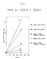
- Fig. 1 is a graph of etch depth vs. number of pulses for five combinations of laser power using a PMMA substrate.
- Plot 101 is the etch depth per pulse of a 308 nm XeCl pulsed excimer laser at a fluence of 760 mJ/cm2 (millijoules per square centimeter).
- Plot 102 is the etch depth per pulse of a 193 nm ArF pulsed excimer laser at a fluence of 85 mJ/cm2.
- Plot 103 is the etch depth per pulse of the time coincident combination of a 193 nm laser at a fluence of 85 mJ/cm2 and a 308 nm laser at a fluence of 760 mJ/cm2.
- Plot 104 is the etch depth per pulse of a 193 nm laser at a fluence of 186 mJ/cm2.
- Plot 105 is the etch depth per pulse of the time coincident combination of a 193 nm laser at a fluence of 186 mJ/cm2 and a 308 nm laser at a fluence of 760 mJ/cm2.
- PMMA does not absorb very much 308 nm radiation.
- a thermal mechanism To etch PMMA with laser pulses at this wavelength, a thermal mechanism must be used. This thermal mechanism requires high fluences (greater than 1 J/cm2) and high repetition rates (greater than 20 Hz) which cause intense local heating and result in considerable thermal damage to the etched substrate.
- etching can be obtained using coincident pulses of 193 nm and 308 nm radiation.
- Plot 101 of Fig. 1 illustrates that, at a fluence of 760mJ/cm2 of 308 nm radiation, the PMMA substrate was not etched to any measurable extent.
- Fig. 1 also illustrates that etching was achieved using 193 nm radiation at fluences of 85 and 186 mJ/cm2.
- the combination of the two wavelengths resulted in a 30 to 100 percent increase in the etch depth per pulse pair.
- the etched area had a smoothness (i.e., no thermal damage) that is typical of laser etching with 193 nm laser pulses alone.
- Fig. 2 illustrates an experiment conducted on PMMA to determine the effect of inserting a time delay between the 193 nm ArF laser pulses and 308 nm XeCl laser pulses.
- the 193 nm laser was set at a fluence of 70 mJ/cm2.
- the 308 nm laser was set at a fluence of 240 mJ/cm2.
- plot 201 illustrates, the 308 nm, longer wavelength laser had no measurable effect on the substrate when used alone, which would be expected because the wavelength of the 308 nm laser is outside the absorption spectrum of PMMA.
- the 193 nm laser in contrast, is well within the absorption spectrum of PMMA and etched the PMMA to a depth of approximately 70 ⁇ m after 500 pulses (plot 202).
- Plot 203 in Fig. 2 clearly illustrates that the combination of the 193 nm laser and the 308 nm laser provided a substantial improvement in etch depth per pulse pair, and that the degree of improvement depended on the temporal relation between pulses at the two wavelengths.
- the effect was not as substantial as when the 193 nm pulse preceded the 308 nm pulse.
- this improvement peaked when the 308 nm pulse followed the 193 nm pulse by approximately 20 to 30 nanoseconds.
- different laser wavelengths will have different optimum time separations.
- the peak in plot 203 would be expected to occur at approximately 40 to 50 nanoseconds of separation using a 248 nm KrF pulsed excimer laser in place of the 193 nm laser. Therefore, the combined effect of the two lasers provides a substantial improvement over using either laser alone, and an even further improvement is provided when the lasers are used in a specific time sequence.
- this time sequence i.e., the optimum length of time between pulses, would be dependent on the type of substrate being ablated, the maximum ablation occurring at different time spacings for different substrates.
- the shorter wavelength, higher photon energy laser pulse should come first in every instance, with the longer wavelength, lower photon energy (not necessarily lower incident energy) laser pulse being applied second.
- the timing of the peak illustrated in Fig. 2 is expected to be independent of the laser power. That is, while the height of the peak will be a function of the incident power, the optimum pulse separation time is not expected to be a function of the incident power. Therefore, the etch depth per pulse may be controlled as a function of the time separation between the two laser pulses for a fixed incident power. In addition, by controlling the pulse separation time it is possible to achieve desirable etch depths with lower incident power levels.
- the improved etch results from the following physical phenomenon: as with ablation, the surface molecules of the substrate are excited to a higher electronic state by a UV laser with a wavelength within the absorption spectrum of the substrate material.
- the excited molecules have an absorption spectrum which includes the longer wavelength laser, and, therefore, will absorb the energy from the second laser where the unexcited substrate does not absorb energy from the second laser. This phenomenon results in ablation of the excited molecules which were not ablated using the single UV laser.
- a molecule when excited to a higher energy state such as a "singlet", it may not reach an energy level sufficient to break the molecular bonds and ablate. When this happens, the singlet molecules form "triplets", which is also an excited state. If no additional energy is added, the triplets will simply reform as surface molecules.
- a second laser with a wavelength within the absorption spectrum of the excited triplets can add sufficient energy to cause the bonds to be broken and ablation to occur. This additional energy will not be necessary to cause ablation of a substantial majority of the molecules where the shorter wavelength laser provides sufficient energy for the bonds to be broken and ablation to occur. However, it will be necessary in some percentage of the cases where the shorter wavelength laser does not provide sufficient energy for ablation. The improvement in etch depth may then be explained by the additional molecules ablated by the second laser.
- 193 nm radiation is used first because that wavelength is within the absorption spectrum of PMMA and excites the substrate molecules sufficiently to cause them to ablate.
- the photon energy is sufficient to excite a number of the surface molecules into a "singlet" state.
- a majority of the molecules in the singlet state have sufficient energy to ablate.
- some of the molecules do not ablate and slide into a triplet state. Molecules in the triplet state can be excited into ablation provided that radiation with sufficient photon energy -- in the case of PMMA, a 308 nm laser -- is incident on the substrate at that point.
- the 308 nm radiation being within the absorption spectrum of the triplet molecules, provides sufficient energy to excite the "triplets" into ablation, resulting in substantially improved etch depths.
- the wavelength of a first laser is selected to be within the absorption band of the substrate in order to sufficiently excite the substrate molecules.
- the wavelength of a second laser is selected to be within the absorption spectrum of the excited triplet molecules. Normally a second laser with a longer (that is, less powerful -- having lower photon energy) wavelength is required, which excites into ablation those molecules not removed by the first laser into ablation, and essentially "cleans" the hole.
- the etch mechanism is a combination of the photochemical effect of the UV photons, which causes bond breaking in a thin layer close to the film's surface, and the thermal effect of the infrared photons, which are absorbed by the UV-sensitized layer allowing ablation.
- the role of the infrared photons is to raise the temperature of the film, which lowers the threshold fluence of UV radiation required to induce photoablative decomposition. It has been previously shown that raising the temperature of a Kapton (trademark of the Du Pont Corporation) polyimide substrate will, under certain circumstances, lower the fluence threshold for ablative etching.
- this technique is useful in etching substrates such as Kapton (trademark of the Du Pont Corporation), which has a high absorption coefficient, and it may be useful in etching other materials and in certain surgical procedures, its usefulness is limited by the heat generated. In addition, its usefulness is further limited by the difficulty of transporting infrared radiation using fiber optics and by the equipment required to generate broad-spectrum plasma radiation. In contrast, the present invention uses a purely photochemical etch mechanism which does not generate detrimental heat within the material being etched.
- Another advantage of the present invention is that it makes use of an ablation technique adaptable to the optical fiber environment.
- the ultraviolet lasers which give the best ablation in Fig. 1 the 193 nm far-UV laser
- longer wavelength lasers e.g., the 308 nm laser
- Fig. 3 illustrates results of an application of the present invention to the ablation of a mylar-type substrate.
- the lasers were conducted through optical fibers.
- the first laser utilized was a 308 nm XeCl pulsed excimer laser at an energy fluence of 80 mJ/cm2, which is within the absorption spectrum of mylar.
- the second laser was a 351 nm XeF pulsed excimer laser at an energy fluence of 100 mJ/cm2, which is outside the absorption spectrum of unexcited mylar.
- Plot 303 of Fig. 3 illustrates the average etch depth per pulse pair obtained by separating the first and second laser pulses in time. It will be noted that the optimum delay time between pulses in Fig. 3 is substantially less than the optimum delay time in Fig. 2, which substantiates the expectation that the optimum delay time will vary depending on the substrate material and/or the frequency of the incident radiation.
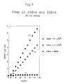
- Fig. 4 illustrates the weight loss in milligrams as a function of the number of pulses for a PMMA substrate.
- Plot 401 illustrates the loss as a function of the number of pulse pairs using a 308 nm laser at a fluence of 800 mJ/cm2.
- the weight loss indicated in plot 401 of Fig. 4 at 308 nm was not a result of etching. It may have been caused by measurement error or by the release of surface gases; however, there was no visible evidence that any etching had taken place.
- Plot 402 illustrates the weight loss as a function of the number of pulse pairs using a 248 nm laser at a fluence of 1.2 J/cm2.
- plot 403 illustrates the weight loss as a function of the number of pulse pairs using a 248 nm laser at a fluence of 1.2 J/cm2 followed by a 308 nm laser at a fluence of 800 mJ/cm2 with a 40 ns delay between the 248 nm and 308 nm pulses.
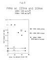
- Fig. 5 is a plot of the weight loss in milligrams vs. the time delay between pulses for a PMMA substrate.
- the lasers are a 193 nm laser at a fluence of 105 mJ/cm2 and a 308 nm laser at a fluence of 165 mJ/cm2.
- Plot 501 illustrates that there was no measurable weight loss after 2000 pulses of the 308 nm laser alone.
- Plot 502 illustrates that there was only about 0.1 mg loss after 2000 pulses of the 193 nm laser.
- Plot 503 illustrates that there was a substantial improvement when the 193 nm laser and 308 nm laser were used with a predetermined time delay. Comparing this figure to Fig. 2, it is clear that the peak improvement occurs at substantially the same time, i.e., at approximately 10-20 ns of delay.
- Fig. 6 illustrates an arrangement for implementing the present invention.
- a first Lambda-Physik 201E ArF pulsed excimer UV laser 10 produces a pulse of 193 nm wavelength when triggered by a first pulse from a Philips PM 5716 pulse generator 30 which is capable of generating a second pulse at a fixed time delay after the first pulse.
- the second pulse triggers a Lambda-Physik 201E XeCl pulsed excimer laser 20 which provides a 308 nm pulsed beam that is reflected from both a first mirror 80 and a second, dielectric mirror 90.
- Mirror 90 is arranged to pass radiation from the 193 nm laser with little or no loss.
- Photodiode 70 absorbs a portion of the radiation from lasers 10 and 20, and its output is displayed on oscilloscope 40 which is triggered by an output from pulse generator 30.
- a Scientech 38-2UV5 powermeter 60 measures the power through the mask (without the polymer).
- UV wavelengths e.g., 193 nm
- these losses may result in damage to the optical fiber.
- very short wavelength ultraviolet laser radiation which is difficult to produce and deliver at high energy fluence, can be used at lower fluence with an additional, longer wavelength laser to achieve desirable etch characteristics.
- the cost of using two lasers is not prohibitive because the power supply and delivery systems can be shared by the two lasers. This makes the present invention especially appealing for laser angioplasty.
- the method described in the present invention is intended to be applicable to any type of substrate which may be etched by ablative photodecomposition. It is particularly adapted to etching organic substrates such as organic polymers, organic tissue, bone and tooth material.
Landscapes
- Physics & Mathematics (AREA)
- Optics & Photonics (AREA)
- Engineering & Computer Science (AREA)
- Plasma & Fusion (AREA)
- Mechanical Engineering (AREA)
- Health & Medical Sciences (AREA)
- Surgery (AREA)
- Life Sciences & Earth Sciences (AREA)
- Heart & Thoracic Surgery (AREA)
- Public Health (AREA)
- Nuclear Medicine, Radiotherapy & Molecular Imaging (AREA)
- Biomedical Technology (AREA)
- Electromagnetism (AREA)
- Medical Informatics (AREA)
- Molecular Biology (AREA)
- Animal Behavior & Ethology (AREA)
- General Health & Medical Sciences (AREA)
- Otolaryngology (AREA)
- Veterinary Medicine (AREA)
- Drying Of Semiconductors (AREA)
- Laser Beam Processing (AREA)
- Lasers (AREA)
- Laser Surgery Devices (AREA)
- Dental Tools And Instruments Or Auxiliary Dental Instruments (AREA)
- Radiation-Therapy Devices (AREA)
- Treatments Of Macromolecular Shaped Articles (AREA)
Applications Claiming Priority (2)
| Application Number | Priority Date | Filing Date | Title |
|---|---|---|---|
| US26447688A | 1988-10-28 | 1988-10-28 | |
| US264476 | 1988-10-28 |
Publications (2)
| Publication Number | Publication Date |
|---|---|
| EP0365754A1 true EP0365754A1 (fr) | 1990-05-02 |
| EP0365754B1 EP0365754B1 (fr) | 1994-11-09 |
Family
ID=23006229
Family Applications (1)
| Application Number | Title | Priority Date | Filing Date |
|---|---|---|---|
| EP89112410A Expired - Lifetime EP0365754B1 (fr) | 1988-10-28 | 1989-07-07 | Ablation par laser ultraviolet et gravure de solides organiques |
Country Status (4)
| Country | Link |
|---|---|
| US (1) | US4925523A (fr) |
| EP (1) | EP0365754B1 (fr) |
| JP (1) | JP2502768B2 (fr) |
| DE (1) | DE68919328T2 (fr) |
Cited By (8)
| Publication number | Priority date | Publication date | Assignee | Title |
|---|---|---|---|---|
| EP0514898A1 (fr) * | 1991-05-21 | 1992-11-25 | Lasag Ag | Impulsion laser pour l'élimination de matière dentaire dure |
| WO1992020288A1 (fr) * | 1991-05-23 | 1992-11-26 | Schirmer Kurt E | Appareil permettant de proceder a des incisions chirurgicales avec effet combine de faisceaux laser thermiques et ionisants |
| WO1996027335A1 (fr) * | 1995-03-03 | 1996-09-12 | Lions Eye Institute | Ablation au laser a deux faisceaux |
| EP0785757A2 (fr) * | 1994-10-13 | 1997-07-30 | The General Hospital Corporation | Appareil d'eclairage lateral de tissus a deux impulsions |
| EP2119528A1 (fr) * | 2008-05-15 | 2009-11-18 | Mitutoyo Corporation | Appareil de traitement laser |
| WO2014154337A3 (fr) * | 2013-03-26 | 2014-12-31 | Fraunhofer-Gesellschaft Zur Forderung Der Angewandten Forschung E. V. | Procédé d'abrasion de matière dure et cassante au moyen d'un rayonnement laser |
| EP2836152A4 (fr) * | 2012-04-12 | 2016-02-17 | Ams Res Corp | Systèmes laser chirurgicaux et techniques de lithotripsie au laser |
| EP4082760A4 (fr) * | 2019-12-27 | 2024-01-10 | Laser Systems Inc. | Procédé d'usinage d'élément en résine, appareil d'usinage d'élément en résine et procédé de fabrication de composant en résine |
Families Citing this family (61)
| Publication number | Priority date | Publication date | Assignee | Title |
|---|---|---|---|---|
| US5324200A (en) * | 1988-08-25 | 1994-06-28 | American Dental Technologies, Inc. | Method for enlarging and shaping a root canal |
| US5123845A (en) * | 1988-08-25 | 1992-06-23 | American Dental Laser, Inc. | Dental laser assembly |
| US5180304A (en) * | 1988-08-25 | 1993-01-19 | American Dental Laser, Inc. | Method for apical fusion of the foramina |
| US5122060A (en) * | 1988-08-25 | 1992-06-16 | American Dental Laser, Inc. | Method for creating an etch in dentin |
| CA2031716C (fr) * | 1989-12-07 | 1996-06-18 | Hiroaki Misawa | Microtritement au laser, le dispositif correspondant |
| US5195163A (en) * | 1991-09-27 | 1993-03-16 | The United States Of America As Represented By The Secretary Of The Navy | Fabrication and phase tuning of an optical waveguide device |
| US5322986A (en) * | 1992-04-06 | 1994-06-21 | Eastman Kodak Company | Methods for preparing polymer stripe waveguides and polymer stripe waveguides prepared thereby |
| US6450641B2 (en) | 1992-06-02 | 2002-09-17 | Lasersight Technologies, Inc. | Method of corneal analysis using a checkered placido apparatus |
| JP3212405B2 (ja) * | 1992-07-20 | 2001-09-25 | 富士通株式会社 | エキシマレーザ加工方法及び装置 |
| US6090100A (en) | 1992-10-01 | 2000-07-18 | Chiron Technolas Gmbh Ophthalmologische Systeme | Excimer laser system for correction of vision with reduced thermal effects |
| USRE37504E1 (en) | 1992-12-03 | 2002-01-08 | Lasersight Technologies, Inc. | Ophthalmic surgery method using non-contact scanning laser |
| US6716210B2 (en) | 1992-12-03 | 2004-04-06 | Lasersight Technologies, Inc. | Refractive surgical laser apparatus and method |
| US5315604A (en) * | 1993-01-28 | 1994-05-24 | International Business Machines Corporation | Optical structure for adjusting the peak power of a laser beam |
| US5656186A (en) * | 1994-04-08 | 1997-08-12 | The Regents Of The University Of Michigan | Method for controlling configuration of laser induced breakdown and ablation |
| US5660746A (en) * | 1994-10-24 | 1997-08-26 | University Of South Florida | Dual-laser process for film deposition |
| US5904678A (en) * | 1995-06-19 | 1999-05-18 | Lasersight Technologies, Inc. | Multizone, multipass photorefractive keratectomy |
| DE19523900C1 (de) * | 1995-06-30 | 1997-01-16 | Bosch Gmbh Robert | Verfahren zur Vorbehandlung von einer zu verklebenden Oberfläche aus Kunststoff |
| US5997529A (en) * | 1996-10-28 | 1999-12-07 | Lasersight Technologies, Inc. | Compound astigmatic myopia or hyperopia correction by laser ablation |
| US6210169B1 (en) | 1997-01-31 | 2001-04-03 | Lasersight Technologies, Inc. | Device and method for simulating ophthalmic surgery |
| WO1999013363A1 (fr) * | 1997-09-08 | 1999-03-18 | Photon Dynamics, Inc. | Procede et appareil de reparation de filtres colores |
| US6054235A (en) * | 1997-09-08 | 2000-04-25 | Photon Dynamics, Inc. | Color filter repair method |
| US6007202A (en) | 1997-10-23 | 1999-12-28 | Lasersight Technologies, Inc. | Eye illumination system and method |
| US6010497A (en) * | 1998-01-07 | 2000-01-04 | Lasersight Technologies, Inc. | Method and apparatus for controlling scanning of an ablating laser beam |
| US6132424A (en) * | 1998-03-13 | 2000-10-17 | Lasersight Technologies Inc. | Smooth and uniform laser ablation apparatus and method |
| US6409718B1 (en) | 1998-02-03 | 2002-06-25 | Lasersight Technologies, Inc. | Device and method for correcting astigmatism by laser ablation |
| JP2000166941A (ja) * | 1998-12-07 | 2000-06-20 | Kazue Yamagishi | 歯表面凹凸形成方法及びこの方法に用いられる歯科用レーザ装置 |
| US6080959A (en) * | 1999-03-12 | 2000-06-27 | Lexmark International, Inc. | System and method for feature compensation of an ablated inkjet nozzle plate |
| US6497701B2 (en) | 1999-04-30 | 2002-12-24 | Visx, Incorporated | Method and system for ablating surfaces with partially overlapping craters having consistent curvature |
| US6341009B1 (en) | 2000-02-24 | 2002-01-22 | Quantronix Corporation | Laser delivery system and method for photolithographic mask repair |
| JP3522654B2 (ja) * | 2000-06-09 | 2004-04-26 | 住友重機械工業株式会社 | レーザ加工装置及び加工方法 |
| US6797944B2 (en) * | 2002-02-01 | 2004-09-28 | Control Screening, Llc | Laser desorption and detection of explosives, narcotics, and other chemical substances |
| US20030155328A1 (en) * | 2002-02-15 | 2003-08-21 | Huth Mark C. | Laser micromachining and methods and systems of same |
| US6969822B2 (en) * | 2003-05-13 | 2005-11-29 | Hewlett-Packard Development Company, L.P. | Laser micromachining systems |
| US7754999B2 (en) | 2003-05-13 | 2010-07-13 | Hewlett-Packard Development Company, L.P. | Laser micromachining and methods of same |
| JP2005102831A (ja) * | 2003-09-29 | 2005-04-21 | Japan Science & Technology Agency | 生体分子損傷方法、および生体分子損傷装置 |
| WO2005057625A2 (fr) * | 2003-12-04 | 2005-06-23 | Matsushita Electric Industrial Co., Ltd. | Procede de formation differentiee de motifs des couches de materiau de film organique mince permettant de ne pas endommager les couches sous-jacentes |
| US7655152B2 (en) * | 2004-04-26 | 2010-02-02 | Hewlett-Packard Development Company, L.P. | Etching |
| US7265772B2 (en) * | 2004-12-16 | 2007-09-04 | Esko Graphics A/S | Beam illumination system and method for producing printing plates |
| US7635362B2 (en) | 2004-12-30 | 2009-12-22 | Lutronic Corporation | Method and apparatus treating area of the skin by using multipulse laser |
| US20070046934A1 (en) * | 2005-08-26 | 2007-03-01 | New Wave Research, Inc. | Multi-function laser induced breakdown spectroscopy and laser ablation material analysis system and method |
| CA2558898C (fr) * | 2005-09-07 | 2013-11-05 | Purdue Research Foundation | Procede d'usinage assiste par laser avec lasers repartis |
| US7750267B2 (en) * | 2006-04-25 | 2010-07-06 | Van Denend Mark E | Apparatus and method for laser engraveable printing plates |
| US7633035B2 (en) | 2006-10-05 | 2009-12-15 | Mu-Gahat Holdings Inc. | Reverse side film laser circuit etching |
| US8604381B1 (en) | 2006-10-12 | 2013-12-10 | Purdue Research Foundation | Integrated laser material processing cell |
| US7977602B2 (en) * | 2007-03-21 | 2011-07-12 | Photon Dynamics, Inc. | Laser ablation using multiple wavelengths |
| US20080289651A1 (en) * | 2007-05-25 | 2008-11-27 | International Business Machines Corporation | Method and apparatus for wafer edge cleaning |
| DE102008040782A1 (de) * | 2008-07-28 | 2010-02-04 | Robert Bosch Gmbh | Bauteilverbund sowie Verfahren zum Herstellen eines Bauteilverbundes |
| WO2014143014A1 (fr) | 2013-03-15 | 2014-09-18 | Triagenics, Llc | Ablation thérapeutique de bourgeon dentaire |
| US10022202B2 (en) | 2013-03-15 | 2018-07-17 | Triagenics, Llc | Therapeutic tooth bud ablation |
| US9402693B2 (en) | 2009-05-11 | 2016-08-02 | Triagenics, Llc | Therapeutic tooth bud ablation |
| KR101770836B1 (ko) * | 2009-08-11 | 2017-08-23 | 하마마츠 포토닉스 가부시키가이샤 | 레이저 가공장치 및 레이저 가공방법 |
| US8512937B2 (en) * | 2010-03-04 | 2013-08-20 | The Regents Of The University Of California | Lithographic dry development using optical absorption |
| DE102011000768B4 (de) * | 2011-02-16 | 2016-08-18 | Ewag Ag | Laserbearbeitungsverfahren und Laserbearbeitungsvorrichtung mit umschaltbarer Laseranordnung |
| US9539681B2 (en) | 2011-11-30 | 2017-01-10 | Board Of Trustees Of Northern Illinois University | Laser assisted machining system for ceramics and hard materials |
| US20130153552A1 (en) * | 2011-12-14 | 2013-06-20 | Gwangju Institute Of Science And Technology | Scribing apparatus and method for having analysis function of material distribution |
| US9438264B1 (en) | 2015-09-10 | 2016-09-06 | Realtek Semiconductor Corp. | High-speed capacitive digital-to-analog converter and method thereof |
| KR20150102180A (ko) * | 2014-02-27 | 2015-09-07 | 삼성디스플레이 주식회사 | 레이저 빔 조사 장치 및 이를 이용한 유기 발광 디스플레이 장치의 제조 방법 |
| EP3685954B1 (fr) * | 2019-01-22 | 2024-01-24 | Synova S.A. | Procédé de découpe de pièce à l'aide d'un faisceau laser complex guidé par jet de fluide |
| CN109894737B (zh) * | 2019-04-17 | 2021-02-09 | 深圳信息职业技术学院 | 一种金属曲面的激光抛光装置以及方法 |
| EP4413935A3 (fr) | 2019-06-06 | 2024-09-18 | TriAgenics, Inc. | Systèmes de sonde d'ablation |
| CN117697166B (zh) * | 2024-02-06 | 2024-04-19 | 中国工程物理研究院激光聚变研究中心 | 在金属薄膜表面利用激光刻蚀有机膜的方法 |
Citations (2)
| Publication number | Priority date | Publication date | Assignee | Title |
|---|---|---|---|---|
| EP0266038A2 (fr) * | 1986-10-29 | 1988-05-04 | Kureha Kagaku Kogyo Kabushiki Kaisha | Appareil pour le traitement du cancer avec des photodiodes |
| DE8807746U1 (de) * | 1988-06-15 | 1988-09-29 | Messerschmitt-Bölkow-Blohm GmbH, 8012 Ottobrunn | Vorrichtung zur Erzeugung eines Laserlichtstrahles |
Family Cites Families (24)
| Publication number | Priority date | Publication date | Assignee | Title |
|---|---|---|---|---|
| US3622742A (en) * | 1970-05-27 | 1971-11-23 | Bell Telephone Labor Inc | Laser machining method and apparatus |
| US3710798A (en) * | 1971-08-30 | 1973-01-16 | American Optical Corp | Laser system for microsurgery |
| US4054094A (en) * | 1972-08-25 | 1977-10-18 | E. I. Du Pont De Nemours And Company | Laser production of lithographic printing plates |
| JPS5418798B2 (fr) * | 1974-08-31 | 1979-07-10 | ||
| US4289378A (en) * | 1978-06-21 | 1981-09-15 | Ernst Remy | Apparatus for adjusting the focal point of an operating laser beam focused by an objective |
| US4408602A (en) * | 1981-01-14 | 1983-10-11 | Asahi Kogaku Kogyo Kabushiki Kaisha | Laser knife device |
| JPS5886787A (ja) * | 1981-11-19 | 1983-05-24 | Nippon Sekigaisen Kogyo Kk | レ−ザ照射装置 |
| US4451503A (en) * | 1982-06-30 | 1984-05-29 | International Business Machines Corporation | Photo deposition of metals with far UV radiation |
| US4440801A (en) * | 1982-07-09 | 1984-04-03 | International Business Machines Corporation | Method for depositing a metal layer on polyesters |
| US4417948A (en) * | 1982-07-09 | 1983-11-29 | International Business Machines Corporation | Self developing, photoetching of polyesters by far UV radiation |
| US4568632A (en) * | 1982-10-07 | 1986-02-04 | International Business Machines Corporation | Patterning of polyimide films with far ultraviolet light |
| US4784135A (en) * | 1982-12-09 | 1988-11-15 | International Business Machines Corporation | Far ultraviolet surgical and dental procedures |
| US4414059A (en) * | 1982-12-09 | 1983-11-08 | International Business Machines Corporation | Far UV patterning of resist materials |
| US4701591A (en) * | 1983-11-07 | 1987-10-20 | Matsushita Electric Industrial Co., Ltd | Apparatus for processing multiple workpieces utilizing a single laser beam source |
| JPS60126171A (ja) * | 1983-12-09 | 1985-07-05 | インタ−ナショナル ビジネス マシ−ンズ コ−ポレ−ション | レ−ザ・カテ−テル装置 |
| US4508749A (en) * | 1983-12-27 | 1985-04-02 | International Business Machines Corporation | Patterning of polyimide films with ultraviolet light |
| US4627436A (en) * | 1984-03-01 | 1986-12-09 | Innoventions Biomedical Inc. | Angioplasty catheter and method for use thereof |
| US4715318A (en) * | 1985-01-17 | 1987-12-29 | Nippon Kogaku K.K. | Photochemical reaction apparatus |
| US4749840A (en) * | 1986-05-16 | 1988-06-07 | Image Micro Systems, Inc. | Intense laser irradiation using reflective optics |
| JPS62289390A (ja) * | 1986-06-10 | 1987-12-16 | Toshiba Corp | レ−ザ−加工機 |
| US4687539A (en) * | 1986-10-29 | 1987-08-18 | International Business Machines Corp. | End point detection and control of laser induced dry chemical etching |
| US4789770A (en) * | 1987-07-15 | 1988-12-06 | Westinghouse Electric Corp. | Controlled depth laser drilling system |
| JPH01273684A (ja) * | 1988-04-27 | 1989-11-01 | Mitsubishi Electric Corp | 分解除去装置 |
| WO1990004358A1 (fr) * | 1988-10-25 | 1990-05-03 | Karl Storz Gmbh & Co. | Procede et dispositif pour detruire un corps solide entoure d'un fluide |
-
1989
- 1989-07-07 EP EP89112410A patent/EP0365754B1/fr not_active Expired - Lifetime
- 1989-07-07 DE DE68919328T patent/DE68919328T2/de not_active Expired - Fee Related
- 1989-07-17 US US07/380,787 patent/US4925523A/en not_active Expired - Lifetime
- 1989-10-09 JP JP1262276A patent/JP2502768B2/ja not_active Expired - Fee Related
Patent Citations (2)
| Publication number | Priority date | Publication date | Assignee | Title |
|---|---|---|---|---|
| EP0266038A2 (fr) * | 1986-10-29 | 1988-05-04 | Kureha Kagaku Kogyo Kabushiki Kaisha | Appareil pour le traitement du cancer avec des photodiodes |
| DE8807746U1 (de) * | 1988-06-15 | 1988-09-29 | Messerschmitt-Bölkow-Blohm GmbH, 8012 Ottobrunn | Vorrichtung zur Erzeugung eines Laserlichtstrahles |
Cited By (22)
| Publication number | Priority date | Publication date | Assignee | Title |
|---|---|---|---|---|
| EP0514898A1 (fr) * | 1991-05-21 | 1992-11-25 | Lasag Ag | Impulsion laser pour l'élimination de matière dentaire dure |
| WO1992020288A1 (fr) * | 1991-05-23 | 1992-11-26 | Schirmer Kurt E | Appareil permettant de proceder a des incisions chirurgicales avec effet combine de faisceaux laser thermiques et ionisants |
| EP0785757A2 (fr) * | 1994-10-13 | 1997-07-30 | The General Hospital Corporation | Appareil d'eclairage lateral de tissus a deux impulsions |
| EP0785757A4 (fr) * | 1994-10-13 | 2000-04-26 | Gen Hospital Corp | Appareil d'eclairage lateral de tissus a deux impulsions |
| WO1996027335A1 (fr) * | 1995-03-03 | 1996-09-12 | Lions Eye Institute | Ablation au laser a deux faisceaux |
| GB2313551A (en) * | 1995-03-03 | 1997-12-03 | Lions Eye Inst | Dual beam laser ablation |
| GB2313551B (en) * | 1995-03-03 | 1998-09-09 | Lions Eye Inst | Dual beam laser ablation |
| US6056741A (en) * | 1995-03-03 | 2000-05-02 | Lions Eye Institute | Dual beam laser ablation |
| CN101579785B (zh) * | 2008-05-15 | 2013-08-28 | 株式会社三丰 | 激光加工装置 |
| US8071910B2 (en) | 2008-05-15 | 2011-12-06 | Mitutoyo Corporation | Laser processing apparatus |
| EP2119528A1 (fr) * | 2008-05-15 | 2009-11-18 | Mitutoyo Corporation | Appareil de traitement laser |
| US10039604B2 (en) | 2012-04-12 | 2018-08-07 | Boston Scientific Scimed, Inc. | Surgical laser systems and laser lithotripsy techniques |
| EP2836152A4 (fr) * | 2012-04-12 | 2016-02-17 | Ams Res Corp | Systèmes laser chirurgicaux et techniques de lithotripsie au laser |
| US9757199B2 (en) | 2012-04-12 | 2017-09-12 | Boston Scientific Scimed, Inc. | Surgical laser systems and laser lithotripsy techniques |
| EP3308735A1 (fr) * | 2012-04-12 | 2018-04-18 | Boston Scientific Scimed, Inc. | Systèmes laser chirurgicaux et techniques de lithotripsie laser |
| US10441359B2 (en) | 2012-04-12 | 2019-10-15 | Boston Scientific Scimed, Inc. | Surgical laser systems and laser lithotripsy techniques |
| EP3610819A1 (fr) * | 2012-04-12 | 2020-02-19 | Boston Scientific Scimed, Inc. | Systèmes de lithotripsie laser |
| US11213352B2 (en) | 2012-04-12 | 2022-01-04 | Boston Scientific Scimed, Inc. | Surgical laser systems and laser lithotripsy techniques |
| US11786306B2 (en) | 2012-04-12 | 2023-10-17 | Boston Scientific Scimed, Inc. | Surgical laser systems and laser lithotripsy techniques |
| WO2014154337A3 (fr) * | 2013-03-26 | 2014-12-31 | Fraunhofer-Gesellschaft Zur Forderung Der Angewandten Forschung E. V. | Procédé d'abrasion de matière dure et cassante au moyen d'un rayonnement laser |
| EP4082760A4 (fr) * | 2019-12-27 | 2024-01-10 | Laser Systems Inc. | Procédé d'usinage d'élément en résine, appareil d'usinage d'élément en résine et procédé de fabrication de composant en résine |
| US11945173B2 (en) | 2019-12-27 | 2024-04-02 | Laser Systems Inc. | Resin member machining method, resin member machining apparatus, and resin component manufacturing method |
Also Published As
| Publication number | Publication date |
|---|---|
| US4925523A (en) | 1990-05-15 |
| JPH02182389A (ja) | 1990-07-17 |
| JP2502768B2 (ja) | 1996-05-29 |
| DE68919328D1 (de) | 1994-12-15 |
| DE68919328T2 (de) | 1995-05-24 |
| EP0365754B1 (fr) | 1994-11-09 |
Similar Documents
| Publication | Publication Date | Title |
|---|---|---|
| US4925523A (en) | Enhancement of ultraviolet laser ablation and etching organic solids | |
| US4784135A (en) | Far ultraviolet surgical and dental procedures | |
| EP0111060B1 (fr) | Retrait de matière biologique par photodécomposition | |
| US8029501B2 (en) | Laser selective cutting by impulsive heat deposition in the IR wavelength range for direct-drive ablation | |
| US5211805A (en) | Cutting of organic solids by continuous wave ultraviolet irradiation | |
| US6231567B1 (en) | Material remover and method | |
| CA2239773C (fr) | Source de lumiere pulsee pour l'exerese de tissus biologiques | |
| US20140065575A1 (en) | Method and apparatus for treatment of solid material including hard tissue | |
| US20090281531A1 (en) | Interventional and therapeutic electromagnetic energy systems | |
| US8074661B2 (en) | Method and apparatus for laser tissue ablation | |
| NL8620191A (nl) | Werkwijze en inrichting voor het afbreken van materiaal met behulp van een laserbundel. | |
| Selting | Laser operating parameters for hard and soft tissue, surgical and PBM management | |
| JP2006504478A (ja) | 硬組織処理用レーザ装置及びその装置の使用方法 | |
| Frank | Biophysical fundamentals for laser application in medicine | |
| Werner et al. | Co2 laser free form processing of hard tissue | |
| Litvack et al. | Laser angioplasty: status and prospects | |
| JPH0829429B2 (ja) | レーザ照射装置 | |
| Srinivasan | Laser‐tissue interactions | |
| Artjushenko et al. | Application of excimer lasers in endoscopic surgery | |
| Jahn et al. | Effects of pulsed lasers on hard biological tissue | |
| Müller et al. | Feasibility of laser angioplasty: physical and technical problems | |
| Hibst | Mechanisms of ultraviolet and mid-infrared tissue ablation | |
| Kim et al. | Ultrashort pulse laser microsurgery system with plasma luminescence feedback control | |
| Jahn et al. | Gross and histological results on bone and meniscus cuts by XeCl-excimer laser radiation | |
| Ivanov et al. | Effect of perfluorocarbon compounds on bone ablation using the free-electron laser |
Legal Events
| Date | Code | Title | Description |
|---|---|---|---|
| PUAI | Public reference made under article 153(3) epc to a published international application that has entered the european phase |
Free format text: ORIGINAL CODE: 0009012 |
|
| AK | Designated contracting states |
Kind code of ref document: A1 Designated state(s): DE FR GB |
|
| 17P | Request for examination filed |
Effective date: 19900820 |
|
| 17Q | First examination report despatched |
Effective date: 19930302 |
|
| GRAA | (expected) grant |
Free format text: ORIGINAL CODE: 0009210 |
|
| AK | Designated contracting states |
Kind code of ref document: B1 Designated state(s): DE FR GB |
|
| REF | Corresponds to: |
Ref document number: 68919328 Country of ref document: DE Date of ref document: 19941215 |
|
| ET | Fr: translation filed | ||
| PLBE | No opposition filed within time limit |
Free format text: ORIGINAL CODE: 0009261 |
|
| STAA | Information on the status of an ep patent application or granted ep patent |
Free format text: STATUS: NO OPPOSITION FILED WITHIN TIME LIMIT |
|
| 26N | No opposition filed | ||
| REG | Reference to a national code |
Ref country code: GB Ref legal event code: IF02 |
|
| PGFP | Annual fee paid to national office [announced via postgrant information from national office to epo] |
Ref country code: DE Payment date: 20050630 Year of fee payment: 17 |
|
| PGFP | Annual fee paid to national office [announced via postgrant information from national office to epo] |
Ref country code: GB Payment date: 20050706 Year of fee payment: 17 |
|
| PGFP | Annual fee paid to national office [announced via postgrant information from national office to epo] |
Ref country code: FR Payment date: 20050708 Year of fee payment: 17 |
|
| PG25 | Lapsed in a contracting state [announced via postgrant information from national office to epo] |
Ref country code: GB Free format text: LAPSE BECAUSE OF NON-PAYMENT OF DUE FEES Effective date: 20060707 |
|
| PG25 | Lapsed in a contracting state [announced via postgrant information from national office to epo] |
Ref country code: DE Free format text: LAPSE BECAUSE OF NON-PAYMENT OF DUE FEES Effective date: 20070201 |
|
| GBPC | Gb: european patent ceased through non-payment of renewal fee |
Effective date: 20060707 |
|
| REG | Reference to a national code |
Ref country code: FR Ref legal event code: ST Effective date: 20070330 |
|
| PG25 | Lapsed in a contracting state [announced via postgrant information from national office to epo] |
Ref country code: FR Free format text: LAPSE BECAUSE OF NON-PAYMENT OF DUE FEES Effective date: 20060731 |