EP0365686B1 - Tube d'affichage fluorescent - Google Patents
Tube d'affichage fluorescent Download PDFInfo
- Publication number
- EP0365686B1 EP0365686B1 EP89904224A EP89904224A EP0365686B1 EP 0365686 B1 EP0365686 B1 EP 0365686B1 EP 89904224 A EP89904224 A EP 89904224A EP 89904224 A EP89904224 A EP 89904224A EP 0365686 B1 EP0365686 B1 EP 0365686B1
- Authority
- EP
- European Patent Office
- Prior art keywords
- fluorescent
- side wall
- segments
- electron beam
- grid
- Prior art date
- Legal status (The legal status is an assumption and is not a legal conclusion. Google has not performed a legal analysis and makes no representation as to the accuracy of the status listed.)
- Expired - Lifetime
Links
Images


Classifications
-
- H—ELECTRICITY
- H01—ELECTRIC ELEMENTS
- H01J—ELECTRIC DISCHARGE TUBES OR DISCHARGE LAMPS
- H01J31/00—Cathode ray tubes; Electron beam tubes
- H01J31/08—Cathode ray tubes; Electron beam tubes having a screen on or from which an image or pattern is formed, picked up, converted, or stored
- H01J31/10—Image or pattern display tubes, i.e. having electrical input and optical output; Flying-spot tubes for scanning purposes
- H01J31/12—Image or pattern display tubes, i.e. having electrical input and optical output; Flying-spot tubes for scanning purposes with luminescent screen
- H01J31/15—Image or pattern display tubes, i.e. having electrical input and optical output; Flying-spot tubes for scanning purposes with luminescent screen with ray or beam selectively directed to luminescent anode segments
-
- H—ELECTRICITY
- H01—ELECTRIC ELEMENTS
- H01J—ELECTRIC DISCHARGE TUBES OR DISCHARGE LAMPS
- H01J2231/00—Cathode ray tubes or electron beam tubes
- H01J2231/12—CRTs having luminescent screens
- H01J2231/125—CRTs having luminescent screens with a plurality of electron guns within the tube envelope
- H01J2231/1255—CRTs having luminescent screens with a plurality of electron guns within the tube envelope two or more neck portions containing one or more guns
Abstract
Claims (2)
- Tube d'affichage fluorescent, comprenant :
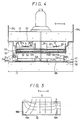
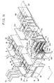
un plan fluorescent (16) à l'intérieur d'un conteneur de type plat (15) ayant des premier et second panneaux (11, 12) en face l'un de l'autre et une paroi latérale périphérique (13), le plan fluorescent (16) étant formé en disposant des segments fluorescents (R, G, B) sur la surface intérieure dudit premier panneau (11) ;
un dispositif de commande de faisceaux d'électrons (17) placé en face dudit plan fluorescent (16) pour diriger des faisceaux d'électrons vers les segments fluorescents (R, G, B) respectifs ; et
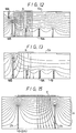
une électrode séparatrice (19) disposée entre ledit plan fluorescent (16) et ledit dispositif de commande de faisceaux d'électrons (17) et comportant des parois de séparation (19A) entre lesdits segments fluorescents (R, G, B), une paroi latérale en saillie (19B) étant disposée sur l'électrode séparatrice (19) dans une partie dudit conteneur (15) où les segments fluorescents (R, G, B) sont disposés à proximité de la paroi latérale périphérique (13), ladite paroi latérale en saillie (19B) s'étendant en direction du dispositif de commande de faisceaux d'électrons (17) en face de la paroi latérale périphérique (13) ;
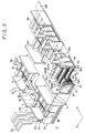
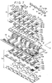
caractérisé en ce que la paroi latérale en saillie (19B) a une hauteur (h2) plus grande que celle des parois de séparation (19A) de l'électrode séparatrice (19), et en ce qu'une paroi latérale en saillie supplémentaire (18A) est placée sur une électrode de basse tension (G3) du dispositif de commande de faisceaux d'électrons (17) dans ladite partie du conteneur (15) où les segments fluorescents (R, G, B) sont disposés à proximité de la paroi latérale périphérique (13), ladite paroi latérale en saillie supplémentaire (18A) s'étendant en direction de l'électrode séparatrice (19) en face de la paroi latérale périphérique (13). - Tube d'affichage fluorescent selon la revendication 1, dans lequel le dispositif de commande de faisceaux d'électrons (17) comprend des cathodes (K) et des grilles (G1 à G3) pour diriger les faisceaux d'électrons vers les segments fluorescents (R, G, B), chacune desdites cathodes (K) comprenant une cathode (K) rectiligne pour chacun desdits segments fluorescents (R, G, B), ou pour plusieurs desdits segments fluorescents (R, G, B) en commun, et dans lequel des parois latérales (27₁, 27₂) sont disposées sur une première grille (G1) desdites grilles (G1 à G3) qui fait face aux cathodes rectilignes (K) , lesdites parois latérales (27₁, 27₂) s'étendant en direction des deux parties d'extrémité des cathodes rectilignes (K).
Applications Claiming Priority (7)
| Application Number | Priority Date | Filing Date | Title |
|---|---|---|---|
| JP74935/88 | 1988-03-29 | ||
| JP63074935A JP2751191B2 (ja) | 1988-03-29 | 1988-03-29 | 螢光表示管 |
| JP7493788A JP2751192B2 (ja) | 1988-03-29 | 1988-03-29 | 螢光表示管 |
| JP7493688A JP2699391B2 (ja) | 1988-03-29 | 1988-03-29 | 螢光表示管 |
| JP74936/88 | 1988-03-29 | ||
| JP74937/88 | 1988-03-29 | ||
| PCT/JP1989/000330 WO1989009482A1 (fr) | 1988-03-29 | 1989-03-29 | Tube d'affichage fluorescent |
Publications (3)
| Publication Number | Publication Date |
|---|---|
| EP0365686A1 EP0365686A1 (fr) | 1990-05-02 |
| EP0365686A4 EP0365686A4 (en) | 1991-08-21 |
| EP0365686B1 true EP0365686B1 (fr) | 1995-11-15 |
Family
ID=27301657
Family Applications (1)
| Application Number | Title | Priority Date | Filing Date |
|---|---|---|---|
| EP89904224A Expired - Lifetime EP0365686B1 (fr) | 1988-03-29 | 1989-03-29 | Tube d'affichage fluorescent |
Country Status (5)
| Country | Link |
|---|---|
| US (1) | US5095244A (fr) |
| EP (1) | EP0365686B1 (fr) |
| KR (1) | KR0125090B1 (fr) |
| DE (1) | DE68924828T2 (fr) |
| WO (1) | WO1989009482A1 (fr) |
Families Citing this family (5)
| Publication number | Priority date | Publication date | Assignee | Title |
|---|---|---|---|---|
| JP2004171968A (ja) * | 2002-11-21 | 2004-06-17 | Hitachi Ltd | 平面型表示装置 |
| GB2404279A (en) * | 2002-11-21 | 2005-01-26 | Hitachi Ltd | Display device comprising box-type spacers located on scanning electrodes |
| US7040764B2 (en) * | 2003-10-23 | 2006-05-09 | Hewlett-Packard Development Company, L.P. | Projection system using ambient light |
| US6987610B2 (en) * | 2003-10-23 | 2006-01-17 | Hewlett-Packard Development Company, L.P. | Projection screen |
| US7293879B2 (en) | 2003-10-23 | 2007-11-13 | Hewlett-Packard Development Company, L.P. | Projection screen |
Family Cites Families (8)
| Publication number | Priority date | Publication date | Assignee | Title |
|---|---|---|---|---|
| JPS60158779A (ja) * | 1984-01-27 | 1985-08-20 | Sony Corp | 表示装置 |
| JPS60253143A (ja) * | 1984-05-28 | 1985-12-13 | Futaba Corp | カラ−蛍光発光管 |
| JPH061675B2 (ja) * | 1984-12-04 | 1994-01-05 | ソニー株式会社 | 螢光表示管 |
| JPH061674B2 (ja) * | 1984-12-04 | 1994-01-05 | ソニー株式会社 | 螢光表示管 |
| JPS61223878A (ja) * | 1985-03-29 | 1986-10-04 | 三菱電機株式会社 | 表示ユニツト |
| JPH0640474B2 (ja) * | 1985-07-08 | 1994-05-25 | 伊勢電子工業株式会社 | 光源用表示管 |
| JPS62150640A (ja) * | 1985-12-24 | 1987-07-04 | Mitsubishi Electric Corp | フラツトマトリクスcrt |
| JP2625727B2 (ja) * | 1987-06-09 | 1997-07-02 | ソニー株式会社 | 螢光表示管 |
-
1989
- 1989-03-24 KR KR1019890003690A patent/KR0125090B1/ko not_active IP Right Cessation
- 1989-03-29 WO PCT/JP1989/000330 patent/WO1989009482A1/fr active IP Right Grant
- 1989-03-29 DE DE68924828T patent/DE68924828T2/de not_active Expired - Fee Related
- 1989-03-29 EP EP89904224A patent/EP0365686B1/fr not_active Expired - Lifetime
- 1989-03-29 US US07/445,654 patent/US5095244A/en not_active Expired - Fee Related
Also Published As
| Publication number | Publication date |
|---|---|
| KR890015186A (ko) | 1989-10-28 |
| US5095244A (en) | 1992-03-10 |
| EP0365686A1 (fr) | 1990-05-02 |
| KR0125090B1 (ko) | 1997-12-11 |
| EP0365686A4 (en) | 1991-08-21 |
| DE68924828D1 (de) | 1995-12-21 |
| DE68924828T2 (de) | 1996-05-02 |
| WO1989009482A1 (fr) | 1989-10-05 |
Similar Documents
| Publication | Publication Date | Title |
|---|---|---|
| EP0405262B1 (fr) | Dispositif d'affichage à panneau plat | |
| US5859508A (en) | Electronic fluorescent display system with simplified multiple electrode structure and its processing | |
| US5565742A (en) | Electronic fluorescent display | |
| EP0133361B1 (fr) | Cellules luminescentes de visualisation | |
| US4973888A (en) | Image display device | |
| US4727284A (en) | Light source display for a large picture screen | |
| US3882342A (en) | Gas discharge display panel for color picture reproduction | |
| EP0333079B1 (fr) | Tube d'affichage à source lumineuse | |
| EP0365686B1 (fr) | Tube d'affichage fluorescent | |
| US4626737A (en) | Mask focusing color picture tube | |
| US4217519A (en) | Isolation busbar for a flat panel display device | |
| EP0434054B1 (fr) | Dispositif d'affichage plat | |
| US4199705A (en) | Modulator structure for a flat panel display device | |
| KR0141700B1 (ko) | 형광 표시판 | |
| US4253040A (en) | Cathode structure for a gas discharge display tube | |
| JPH0614395Y2 (ja) | 平形表示装置 | |
| JP2751192B2 (ja) | 螢光表示管 | |
| JPH01235152A (ja) | 光源用表示管 | |
| JP2751191B2 (ja) | 螢光表示管 | |
| JP2890571B2 (ja) | 平面型表示装置 | |
| AU638321B2 (en) | Light source display tube | |
| JPS60189849A (ja) | 平板形陰極線管 | |
| JP2890572B2 (ja) | 平面型表示装置 | |
| JPH0245898Y2 (fr) | ||
| JPS60193245A (ja) | 平板形カラ−陰極線管 |
Legal Events
| Date | Code | Title | Description |
|---|---|---|---|
| PUAI | Public reference made under article 153(3) epc to a published international application that has entered the european phase |
Free format text: ORIGINAL CODE: 0009012 |
|
| 17P | Request for examination filed |
Effective date: 19891127 |
|
| AK | Designated contracting states |
Kind code of ref document: A1 Designated state(s): DE FR GB NL |
|
| A4 | Supplementary search report drawn up and despatched |
Effective date: 19910628 |
|
| AK | Designated contracting states |
Kind code of ref document: A4 Designated state(s): DE FR GB NL |
|
| 17Q | First examination report despatched |
Effective date: 19930906 |
|
| GRAA | (expected) grant |
Free format text: ORIGINAL CODE: 0009210 |
|
| AK | Designated contracting states |
Kind code of ref document: B1 Designated state(s): DE FR GB NL |
|
| REF | Corresponds to: |
Ref document number: 68924828 Country of ref document: DE Date of ref document: 19951221 |
|
| ET | Fr: translation filed | ||
| PLBE | No opposition filed within time limit |
Free format text: ORIGINAL CODE: 0009261 |
|
| STAA | Information on the status of an ep patent application or granted ep patent |
Free format text: STATUS: NO OPPOSITION FILED WITHIN TIME LIMIT |
|
| 26N | No opposition filed | ||
| PGFP | Annual fee paid to national office [announced via postgrant information from national office to epo] |
Ref country code: FR Payment date: 20010313 Year of fee payment: 13 |
|
| PGFP | Annual fee paid to national office [announced via postgrant information from national office to epo] |
Ref country code: DE Payment date: 20010319 Year of fee payment: 13 |
|
| PGFP | Annual fee paid to national office [announced via postgrant information from national office to epo] |
Ref country code: GB Payment date: 20010328 Year of fee payment: 13 |
|
| PGFP | Annual fee paid to national office [announced via postgrant information from national office to epo] |
Ref country code: NL Payment date: 20010330 Year of fee payment: 13 |
|
| REG | Reference to a national code |
Ref country code: GB Ref legal event code: IF02 |
|
| PG25 | Lapsed in a contracting state [announced via postgrant information from national office to epo] |
Ref country code: GB Free format text: LAPSE BECAUSE OF NON-PAYMENT OF DUE FEES Effective date: 20020329 |
|
| PG25 | Lapsed in a contracting state [announced via postgrant information from national office to epo] |
Ref country code: NL Free format text: LAPSE BECAUSE OF NON-PAYMENT OF DUE FEES Effective date: 20021001 Ref country code: DE Free format text: LAPSE BECAUSE OF NON-PAYMENT OF DUE FEES Effective date: 20021001 |
|
| GBPC | Gb: european patent ceased through non-payment of renewal fee |
Effective date: 20020329 |
|
| PG25 | Lapsed in a contracting state [announced via postgrant information from national office to epo] |
Ref country code: FR Free format text: LAPSE BECAUSE OF NON-PAYMENT OF DUE FEES Effective date: 20021129 |
|
| NLV4 | Nl: lapsed or anulled due to non-payment of the annual fee |
Effective date: 20021001 |
|
| REG | Reference to a national code |
Ref country code: FR Ref legal event code: ST |