EP0364695B1 - Anhängerkupplung - Google Patents
Anhängerkupplung Download PDFInfo
- Publication number
- EP0364695B1 EP0364695B1 EP89115349A EP89115349A EP0364695B1 EP 0364695 B1 EP0364695 B1 EP 0364695B1 EP 89115349 A EP89115349 A EP 89115349A EP 89115349 A EP89115349 A EP 89115349A EP 0364695 B1 EP0364695 B1 EP 0364695B1
- Authority
- EP
- European Patent Office
- Prior art keywords
- coupling
- indicator
- pin
- bore
- housing
- Prior art date
- Legal status (The legal status is an assumption and is not a legal conclusion. Google has not performed a legal analysis and makes no representation as to the accuracy of the status listed.)
- Expired - Lifetime
Links
Images


Classifications
-
- B—PERFORMING OPERATIONS; TRANSPORTING
- B60—VEHICLES IN GENERAL
- B60D—VEHICLE CONNECTIONS
- B60D1/00—Traction couplings; Hitches; Draw-gear; Towing devices
- B60D1/01—Traction couplings or hitches characterised by their type
- B60D1/06—Ball-and-socket hitches
- B60D1/065—Ball-and-socket hitches characterised by the hitch mechanism
-
- B—PERFORMING OPERATIONS; TRANSPORTING
- B60—VEHICLES IN GENERAL
- B60D—VEHICLE CONNECTIONS
- B60D1/00—Traction couplings; Hitches; Draw-gear; Towing devices
- B60D1/01—Traction couplings or hitches characterised by their type
- B60D1/06—Ball-and-socket hitches
Definitions
- the invention relates to a trailer coupling, in particular a ball coupling with the features in the preamble of the main claim.
- a snap-in display according to the features of the preamble of the main claim is known from US-C-4 271 401. These are several electrical contact switches that are connected in a mutually dependent manner. Two of these switches are operated by the movable pan of the coupling mechanism. Additional switches are connected to the breakaway device. If the coupling is not correctly engaged, an electrical signal is emitted via the switches and an alarm, in particular a siren, is triggered.
- the known coupling requires a complex control circuit and an electrical power supply from the towing vehicle. The click indicator only works if the power cable of the Trailer is plugged into the towing vehicle.
- GB-C-912 217 shows a trailer coupling that can only be locked in the calotte of the coupling head if the ball head is seated correctly.
- a spring-loaded locking pin is provided, which is connected to the locking mechanism consisting of two pivot levers. As long as the ball head is not properly engaged, the locking pin inhibits the locking mechanism. The ball head only pushes the locking pin back in the correct locking position, which releases the locking mechanism.
- the invention solves this problem with a snap-in indicator integrated into the clutch housing, consisting of a bore open to the calotte with a spring-loaded mechanical signal pin.
- a snap-in indicator integrated into the clutch housing, consisting of a bore open to the calotte with a spring-loaded mechanical signal pin.
- the signal pin can be designed differently.
- a spring-loaded indicator pin is provided, which is pressed outward by the clutch housing when the clutch head snaps in and confirms the snap-in position by a display area which is only visible then.
- the indicator pin does not protrude beyond the clutch housing when the clutch is open. Otherwise there would be a risk that it would be sheared off at the exposed trailer coupling when maneuvering.
- the indicator pin according to the invention only emerges from the clutch housing when the clutch is engaged and there is no longer any risk of shear.
- a light display can appear in addition to the mechanical display.
- a lamp can be integrated directly into the coupling housing.
- a connection to the lighting system of the towing vehicle is also possible, the locking position being communicated to the driver via a control lamp in the dashboard.
- an electrical contact surface can be provided on the mechanical display pin for signal generation.
- a trailer coupling (1) here a ball coupling
- the coupling housing (3) contains a coupling mechanism (5) which is opened for coupling and, in the correct engagement position, locks the engagement of the ball head (6) and coupling housing (3).
- the trailer coupling (1) has a snap-in indicator (2), which clearly informs the operator whether the coupling is correctly engaged or not.
- the lock indicator (2) is only activated when the spherical cap (4) and the ball head (6) are engaged so far that the coupling can no longer disengage.
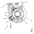
- FIGS. 1 and 2 a mechanical or mechanical / electrical latching display is shown.
- Fig. 1 shows the trailer hitch (1) in the open, ie disengaged position.
- the click indicator (2) consists of a hole (15) and a signal pin (7).
- the bore (15) and the signal pin (7) are preferably cylindrical.
- the bore (15) penetrates the clutch housing (3) radially and is open to the calotte (84) and to the outside.
- the bore (15) is arranged on the central longitudinal axis of the clutch housing (3) and is oriented obliquely forward at an angle of approximately 55 ° to the horizontal. It is therefore ergonomically favorable in the operator's point of view.
- the signal pin (7) is designed as a spring-loaded indicator pin (8). It is guided to move longitudinally in the bore (15) and, when the clutch is open, projects into the cap (4) under the force of the spring (14). It stands approx. 3 mm over the calotte wall (4). On the outside, the indicator pin (8) in this coupling position is flush with the surface of the coupling housing (3) or is arranged recessed.
- the indicator pin (8) is only actuated when the spherical cap (4) and the ball head (6) are already in engagement so far that they can no longer automatically disengage.
- the indicator pin (8) is approximately this dimension longer than the bore (15) and protrudes correspondingly far beyond the clutch housing (3) when the clutch (1) is engaged (see FIG. 2).
- the size of the overhang can vary with different bore diameters.
- the ball head (6) presses the indicator pin (8) outwards against the spring force, as a result of which it protrudes through the clutch housing (3).
- a display surface (10) on the jacket of the display pin (8) is visible, which is easily visible when coupling due to the inclined bore and pin arrangement.
- the display area (10) is green, which indicates the correct setting.
- the top surface (11) of the indicator pin (8) can also be colored, for example in red. As long as the coupling does not engage correctly, only the red cover surface (11) is visible, which clearly indicates to the operator that the coupling is open.
- the captive indicator pin (8) consists of a shaft (13) and a plate (11) forming the top surface, which is pressed into a corresponding shaft bore via a bolt (12).
- the spring (14) is in the bore area guided to the shaft (14) and supported on one side by a radially projecting, annular collar (16) in the bore (15).
- the collar (16) is arranged near the outside of the housing.
- the spring (14) presses against the widened end of the shaft (13) with which it is also guided in the bore (15).
- the plate (11) protrudes radially over the shaft (13) and is supported in an overlapping manner on the collar (16).
- a light indicator () occur.
- this consists of an electric light which is integrated in the front area of the clutch housing (3). It is operated by a switch in the locked position.
- an electrical signal connection to the lighting system of the towing vehicle can also be created, which is closed when the lighting plug is inserted. In the driver's field of vision, for example on the dashboard, a lamp then signals the correct locking position.
- the display pin (8) is provided with an electrical contact surface (19) which, when the display pin (8) is pushed out, closes a circuit for the lamp (18) or the display in the towing vehicle. When the clutch is open, however, the circuit is interrupted.
- an outwardly projecting housing collar with a corresponding bore can be provided instead of the wall of the clutch housing (3) thickened in the spherical cap region (see FIGS. 1 and 2).
- This is designed to be stable to avoid damage and firmly connected to the clutch housing. It also protects the indicator pin in its hole.
- the light indicator (18) can be arranged at any point on the trailer coupling that is visible to the operator when coupling and uncoupling. It is also possible to integrate the light indicator in the spring pin (8), in particular to arrange it in the top surface (11).
Landscapes
- Engineering & Computer Science (AREA)
- Transportation (AREA)
- Mechanical Engineering (AREA)
- Lighting Device Outwards From Vehicle And Optical Signal (AREA)
- Details Of Connecting Devices For Male And Female Coupling (AREA)
- Arrangement And Mounting Of Devices That Control Transmission Of Motive Force (AREA)
- Pivots And Pivotal Connections (AREA)
- Snaps, Bayonet Connections, Set Pins, And Snap Rings (AREA)
Description
- Die Erfindung betrifft eine Anhängerkupplung, insbesondere eine Kugelkopfkupplung mit den Merkmalen im Oberbegriff des Hauptanspruchs.
- Bei Anhängerkupplungen, speziell Kugelkopfkupplungen, besteht das Problem, daß das Kupplungsgehäuse beim Ankuppeln manchmal nicht richtig und von der Bedienungsperson unbemerkt auf dem Kugelkopf des Zugfahrzeuges eingehängt wird. Das Kupplungsgehäuse liegt dann nur lose auf dem Kugelkopf auf. Die Kupplung kann sich während der Fahrt lösen, was häufig zu Unfällen führt.
- Eine Einrastanzeige entsprechend den Merkmalen des Oberbegriffs des Hauptanspruchs ist aus der US-C-4 271 401 bekannt. Es handelt sich hierbei um mehrere elektrische Kontaktschalter, die in gegenseitiger Abhängigkeit geschaltet sind. Zwei dieser Schalter werden durch die bewegliche Pfanne der Kupplungsmechanik betätigt. Weitere Schalter sind mit der Abreißsicherung verbunden. Ist die Kupplung nicht korrekt eingerastet, wird über die Schalter ein elektrisches Signal abgegeben und ein Alarm, insbesondere eine Sirene, ausgelöst. Die vorbekannte Kupplung benötigt eine aufwendige Steuerschaltung und eine elektrische Stromversorgung vom Zugfahrzeug. Die Einrastanzeige funktioniert nur, wenn das Stromkabel des Anhängers am Zugfahrzeug eingesteckt ist.
- Die GB-C-912 217 zeigt eine Anhängerkupplung, die sich nur bei einem korrekten Sitz des Kugelkopfes in der Kalotte des Kupplungskopfes verriegeln läßt. Hierfür ist ein federbelasteter Sperrstift vorgesehen, der mit der aus zwei Schwenkhebeln bestehenden Schließmechanik verbunden ist. Solange der Kugelkopf nicht korrekt eingerastet ist, hemmt der Sperrstift die Schließmechanik. Erst in der korrekten Einraststellung schiebt der Kugelkopf den Sperrstift zurück, wodurch die Schließmechanik freigeben wird.
- Es ist daher Aufgabe der vorliegenden Erfindung, eine Kontrollmöglichkeit für das korrekte Einrasten der Kupplung aufzuzeigen, die geringen Bauaufwand erfordert, sowie eine hohe Betriebssicherheit und Anzeigegenauigkeit besitzt.
- Die Erfindung löst diese Aufgabe mit einer in das Kupplungsgehäuse integrierten Einrastanzeige, bestehend aus einer zur Kalotte offenen Bohrung mit einem federbelasteten mechanischen Signalstift. Wenn die Kalotte den Kupplungskopf, speziell einen Kugelkopf, unter dichter Anlage umgreift, wird die Einrastanzeige betätigt. Dies geschieht erst, wenn Kupplungskopf und Kalotte soweit angenähert sind, daß ein sicheres Einrasten gewährleistet ist.
- Der Signalstift kann unterschiedlich ausgebildet sein. In der Ausführungsform als mechanische oder mechanisch/elektrische Einrastanzeige ist ein federbelasteter Anzeigestift vorgesehen, der beim Einrasten vom Kupplungskopf durch das Kupplungsgehäuse nach außen gedrückt wird und die Einraststellung durch eine dann erst sichtbare Anzeigefläche bestätigt.
- Für die Betriebssicherheit ist es besonders wichtig, daß der Anzeigestift bei geöffneter Kupplung nicht über das Kupplungsgehäuse nach außen vorsteht. Es bestünde sonst die Gefahr, daß er an der exponierten Anhängerkupplung beim Rangieren abgeschert wird. Der erfindungsgemäße Anzeigestift tritt erst bei eingerasteter Kupplung, wenn keine Abschergefahr mehr besteht, aus dem Kupplungsgehäuse.
- Um die Einraststellung besonders deutlich optisch anzuzeigen, kann neben die mechanische Anzeige eine Leuchtanzeige treten. Hierbei kann eine Lampe direkt in das Kupplungsgehäuse integriert sein. Es ist aber auch eine Verbindung zur Lichtanlage des Zugfahrzeuges möglich, wobei die Einraststellung dem Fahrer über eine Kontrolleuchte im Armaturenbrett mitgeteilt wird. Zur Signalerzeugung kann einerseits am mechanischen Anzeigestift eine elektrische Kontaktfläche vorgesehen sein.
- In den Unteransprüchen sind weitere vorteilhafte Ausgestaltungen der Einrastanzeige angegeben.
- Die Erfindung ist in den Zeichnungen beispielsweise und schematisch dargestellt. Im einzelnen zeigen:
- Fig. 1 und 2: im Längsschnitt eine Anhängerkupplung mit einer mechanischen Einrastanzeige in geöffneter und geschlossener Stellung und
- Fig. 3: eine Anhängerkupplung mit einer elektrischen Einrastanzeige.
- In den Zeichnungen ist jeweils der vordere Abschnitt einer Anhängerkupplung (1), hier einer Kugelkopf-Kupplung dargestellt. Sie besteht aus einen mit der Anhängerdeichsel verbundenen Kupplungsgehäuse (3), das mit einer innenliegenden Kalotte (4) den Kupplungskopf, hier einen Kugelkopf (6), umgreift. Der Kugelkopf (6) ist über den Kupplungshals mit dem Zugfahrzeug verbunden. Das Kupplungsgehäuse (3) beinhaltet eine Kupplungsmechanik (5), die zum Ankuppeln geöffnet wird und in korrekter Einraststellung den Eingriff von Kugelkopf (6) und Kupplungsgehäuse (3) verriegelt.
- Die Anhängerkupplung (1) besitzt eine Einrastanzeige (2), die der Bedienungsperson eindeutig mitteilt, ob die Kupplung korrekt eingerastet ist oder nicht. Die Einrastanzeige (2) wird erst dann betätigt, wenn die Kalotte (4) und der Kugelkopf (6) soweit im Eingriff stehen, daß die Kupplung nicht mehr ausrasten kann.
- Im Ausführungsbeispiel der Figuren 1 und 2 ist eine mechanische bzw. mechanisch/elektrische Einrastanzeige dargestellt.
- Fig. 1 zeigt die Anhängerkupplung (1) in offener, das heißt ausgerasteter Stellung. Die Einrastanzeige (2) besteht aus einer Bohrung (15) und einem Signalstift (7). Die Bohrung (15) und der Signalstift (7) sind vorzugsweise Zylindrisch. Die Bohrung (15) durchsetzt das Kupplungsgehäuse (3) radial und ist zur Kalotte (84), sowie nach außen offen. Die Bohrung (15) ist auf der Mittel-Längsachse des Kupplungsgehäuses (3) angeordnet und dabei in einem Winkel von ca. 55° gegen die Horizontale schräg nach vorn ausgerichtet. Sie liegt damit ergonomisch günstig im Blickwinkel der Bedienungsperson.
- Der Signalstift (7) ist als federbelasteter Anzeigestift (8) ausgebildet. Er ist in der Bohrung (15) längsbeweglich geführt und ragt bei geöffneter Kupplung unter der Kraft der Feder (14) in die Kalotte (4). Er steht hierbei ca. 3 mm über die Kalottenwand (4) vor. Außenseitig schließt der Anzeigestift (8) in dieser Kupplungsstellung bündig mit der Oberfläche des Kupplungsgehäuses (3) ab oder ist versenkt angeordnet.
- Bei einem Überstand von ca. 3 mm wird der Anzeigestift (8) erst dann betätigt, wenn die Kalotte (4) und der Kugelkopf (6) bereits soweit im Eingriff stehen, daß sie selbstätig nicht mehr ausrasten können. Der Anzeigestift (8) ist etwa um dieses Maß länger als die Bohrung (15) und steht bei eingerasteter Kupplung (1) entsprechend weit über das Kupplungsgehäuse (3) vor (vgl. Fig. 2). Das Maß des Überstands kann mit unterschiedlichen Bohrungsdurchmessern variieren.
- Bei eingerasteter Kupplung drückt der Kugelkopf (6) gemäß Fig. 2 den Anzeigestift (8) gegen die Federkraft nach außen, wodurch dieser über das Kupplungsgehäuse (3) vortritt. Hierbei wird eine Anzeigefläche (10) am Mantel des Anzeigestiftes (8) sichtbar, die durch die geneigte Bohrungs- und Stiftanordnung beim Ankuppeln gut sichtbar ist. Um das Einrasten außer durch die Stiftstellung auch optisch auffällig und leicht verständlich mitzuteilen, ist die Anzeigefläche (10) in grüner Farbe gehalten, was korrekte Einstellung signalisiert. Demgegenüber kann auch die Deckfläche (11) des Anzeigestiftes (8) farblich gestaltet sein, beispielsweise in rot. Solange die Kupplung nicht korrekt einrastet, ist nur die rote Deckfläche (11) sichtbar, die den Bediener unmißverständlich auf die offene Kupplung hinweist.
- Der unverlierbare Anzeigestift (8) besteht aus einem Schaft (13) und einer die Deckfläche bildenden Platte (11), die über einen Bolzen (12) in eine entsprechende Schachtbohrung eingepreßt ist. Die Feder (14) ist im Bohrungsbereich auf dem Schaft (14) geführt und stützt sich auf der einen Seite an einem radial vorspringenden, ringförmigen Kragen (16) in der Bohrung (15) ab. Der Kragen (16) ist nahe der Gehäuseaußenseite angeordnet. Auf der anderen Seite drückt die Feder (14) gegen das verbreiterte Ende des Schaftes (13), mit dem dieser auch in der Bohrung (15) geführt ist. Auf der anderen Seite steht die Platte (11) radial über den Schaft (13) vor und stützt sich überlappend auf den Kragen (16) ab.
- Wie Fig. 3 verdeutlicht, kann neben die mechanische Anzeige gem. Fig. 1 und 2 eine Leuchtanzeige (18) treten. Diese besteht im gezeigten Ausführungsbeispiel aus einer elektrischen Leuchte, die im vorderen Bereich des Kupplungsgehäuses (3) integriert ist. Sie wird in Einraststellung von einem Schalter betätigt. Alternativ oder zusätzlich kann auch eine elektrische Signalverbindung zur Lichtanlage des Zugfahrzeuges geschaffen werden, die beim Einstecken des Beleuchtungssteckers geschlossen wird. Im Sichtbereich des Fahrers, beispielsweise am Armaturenbrett signalisiert eine Lampe dann die korrekte Einraststellung.
- Im Ausführungsbeispiel der Fig. 1 ist der Anzeigestift (8) mit einer elektrischen Kontaktfläche (19) versehen, die bei herausgedrücktem Anzeigestift (8) einen Stromkreis für die Leuchte (18) oder die Anzeige im Zugfahrzeug schließt. Bei offener Kupplung ist der Stromkreis hingegen unterbrochen.
- Alternativen zu den gezeigten Ausführungsbeispielen sind in verschiedener Weise möglich. Zum einen kann statt der im Kalottenbereich verdickten Wand des Kupplungsgehäuses (3) (vgl. Fig. 1 und 2) ein nach außen ragender Gehäusekragen mit einer entsprechenden Bohrung vorgesehen sein. Dieser ist zur Vermeidung von Beschädigungen stabil ausgebildet und fest mit dem Kupplungsgehäuse verbunden. Er schützt dadurch auch den in seiner Bohrung geführten Anzeigestift. Die Leuchtanzeige (18) kann an einer beliebigen, für die Bedienungsperson beim An- und Abkuppeln einsehbaren Stelle der Anhängerkupplung angeordnet sein. Es ist dabei auch möglich, die Leuchtanzeige in den Federstift (8) zu integrieren, insbesondere in der Deckfläche (11) anzuordnen.
-
- 1 Anhängerkupplung, Kugelkopf-Kupplung,
- 2 Einrastanzeige
- 3 Kupplungsgehäuse
- 4 Kalotte, Kalottenwand
- 5 Kupplungsmechanik
- 6 Kupplungkopf, Kugelkopf
- 7 Signalstift
- 8 Anzeigestift
- 9
- 10 Anzeigefläche
- 11 Deckfläche, Platte
- 12 Bolzen
- 13 Schaft
- 14 Feder
- 15 Bohrung
- 16 Kragen
- 17
- 18 Leuchte, Leuchtanzeige
- 19 elektrische Kontaktfläche
Claims (6)
- Anhängerkupplung, insbesondere Kugelkopf-Kupplung, bestehend aus einem Kupplungsgehäuse (3), das mit einer Kalotte (4) den Kupplungskopf (6) umgreift, wobei das Kupplungsgehäuse (3) eine zur Kalotte (4) offene Bohrung (15) mit einem Signalstift (7) aufweist, dadurch gekennzeichnet, daß der Signalstift (7) als federbelasteter (14) Anzeigestift (8) ausgebildet ist, der in der das Kupplungsgehäuse (3) durchsetzenden Bohrung (15) längsbeweglich geführt ist und an seinem außenliegenden Ende eine Anzeigefläche (10) trägt.
- Anhängerkupplung nach Anspruch 1, dadurch gekennzeichnet, daß der Anzeigestift (8) eine größere Länge als die Bohrung (15) aufweist und bei gelöster Kupplung nach innen in die Kalotte (4) ragt und außenseitig gegenüber der Oberfläche des Kupplungsgehäuses (3) bündig abschließt oder zurückversetzt angeordnet ist.
- Anhängerkupplung nach Anspruch 1 oder 2, dadurch gekennzeichnet, daß die Feder (14) auf dem Schaft (13) des Anzeigestiftes (8) geführt und zwischen einem vorspringenden Kragen (16) in der Bohrung (15) und dem verbreiterten Schaftende eingespannt ist, wobei der Anzeigestift (8) außenseitig eine den Kragen (16) überlappende Deckplatte (11) aufweist.
- Anhängerkupplung nach Anspruch 1 oder einem der folgenden, dadurch gekennzeichnet, daß die Anzeigefläche (10) am Mantel des Schaftes (13) angeordnet ist.
- Anhängerkupplung nach Anspruch 1 oder einem der folgenden, dadurch gekennzeichnet, daß der Anzeigestift (8) eine elektrische Kontaktfläche (19) aufweist.
- Anhängerkupplung nach Anspruch 5, dadurch gekennzeichnet, daß am Kupplungsgehäuse (3) eine Leuchte (18) angeordnet ist.
Applications Claiming Priority (2)
| Application Number | Priority Date | Filing Date | Title |
|---|---|---|---|
| DE8811433U | 1988-09-09 | ||
| DE8811433U DE8811433U1 (de) | 1988-09-09 | 1988-09-09 | Anhängerkupplung |
Publications (2)
| Publication Number | Publication Date |
|---|---|
| EP0364695A1 EP0364695A1 (de) | 1990-04-25 |
| EP0364695B1 true EP0364695B1 (de) | 1993-01-13 |
Family
ID=6827760
Family Applications (1)
| Application Number | Title | Priority Date | Filing Date |
|---|---|---|---|
| EP89115349A Expired - Lifetime EP0364695B1 (de) | 1988-09-09 | 1989-08-19 | Anhängerkupplung |
Country Status (3)
| Country | Link |
|---|---|
| EP (1) | EP0364695B1 (de) |
| DE (2) | DE8811433U1 (de) |
| ES (1) | ES2037357T3 (de) |
Families Citing this family (3)
| Publication number | Priority date | Publication date | Assignee | Title |
|---|---|---|---|---|
| DE4421209C1 (de) * | 1994-06-17 | 1995-07-27 | Kober Ag | Verfahren und Vorrichtung zum Dämpfen der Schlingerbewegung von Fahrzeuganhängern |
| DE202009011720U1 (de) | 2009-08-28 | 2009-12-03 | Gebr. Vitte Gmbh & Co. | Mit einer Kontrolleinrichtung versehene Kugelkopfkupplung |
| DE202009011721U1 (de) * | 2009-08-28 | 2009-12-03 | Gebr. Vitte Gmbh & Co. | Kugelkopfkupplung für einen Anhänger |
Family Cites Families (6)
| Publication number | Priority date | Publication date | Assignee | Title |
|---|---|---|---|---|
| GB912217A (en) * | 1960-08-10 | 1962-12-05 | Howarth Padgett Henry | Improvements in or relating to couplers for connecting trailers to towing vehicles |
| FR1488479A (fr) * | 1966-07-12 | 1967-07-13 | Dispositif accouplant automatiquement un véhicule tracteur et sa remorque ainsi que leurs circuits de freinage respectifs | |
| US3858907A (en) * | 1973-06-21 | 1975-01-07 | Raden Leslie T Van | Ball and socket mechanical and electrical trailer hitch |
| US4209184A (en) * | 1978-08-30 | 1980-06-24 | Byers Dwight R | Self-locking trailer hitch assembly |
| US4271401A (en) * | 1979-08-09 | 1981-06-02 | Tri Delta Industries, Inc. | Safety trailer hitch |
| US4593264A (en) * | 1983-10-19 | 1986-06-03 | Engle Edgar R | Trailer hitch signaling device |
-
1988
- 1988-09-09 DE DE8811433U patent/DE8811433U1/de not_active Expired
-
1989
- 1989-08-19 ES ES198989115349T patent/ES2037357T3/es not_active Expired - Lifetime
- 1989-08-19 DE DE8989115349T patent/DE58903277D1/de not_active Expired - Lifetime
- 1989-08-19 EP EP89115349A patent/EP0364695B1/de not_active Expired - Lifetime
Also Published As
| Publication number | Publication date |
|---|---|
| DE8811433U1 (de) | 1988-10-27 |
| DE58903277D1 (de) | 1993-02-25 |
| EP0364695A1 (de) | 1990-04-25 |
| ES2037357T3 (es) | 1993-06-16 |
Similar Documents
| Publication | Publication Date | Title |
|---|---|---|
| EP0228599B1 (de) | Skibindung mit drahtloser Übertragungsstrecke | |
| DE102008000799A1 (de) | Sattelkupplung | |
| DE69627370T2 (de) | Anzeigemittel in einem bremszylinder für eine fahrzeugbremse | |
| DE102021109065B3 (de) | Kupplungsbolzen für ein Zugfahrzeug eines Fahrzeugverbundes | |
| EP0364695A1 (de) | Anhängerkupplung | |
| DE9207523U1 (de) | Steckdose für eine mehrpolige Steckvorrichtung | |
| DE102021109066B4 (de) | Kupplungsvorrichtung für ein in Zugrichtung hinteres Fahrzeug eines Fahrzeugverbundes | |
| EP3818796A1 (de) | Verschleissanzeige eines kugelkopfs einer anhängerkupplung | |
| DE2606732A1 (de) | Warnvorrichtung zur fehlerfreien bedienung einer schluessel-betaetigten einrichtung in fahrzeugen | |
| EP3210857A1 (de) | Königszapfenvorrichtung für ein aufliegerlenksystem | |
| EP4323261B1 (de) | Zugsattelzapfen für einen sattelauflieger eines sattelkraftfahrzeugs | |
| DE19721392A1 (de) | Tankdeckelerkennungssystem | |
| DE3144986A1 (de) | Vorrichtung zum messen der stuetzlast eines einachsigen anhaengers | |
| EP1398185B1 (de) | Anhängekupplung | |
| EP0687583A1 (de) | Verfahren und Vorrichtung zum Dämpfen der Schlingerbewegung von Fahrzeuganhängern | |
| DE102024116068B3 (de) | Indikatoreinheit | |
| DE1555378C3 (de) | ||
| EP2268511B1 (de) | Vorrichtung zum betätigen von schlössern, insbesondere an fahrzeugen | |
| DE4005840C2 (de) | ||
| DE2659268A1 (de) | Loesbarer endabschluss eines kabels | |
| DE102022121420A1 (de) | Verschleißring und Verschlusshaken für ein Sattelkupplungsschloss einer Sattelkupplung einer Sattelzugmaschine eines Sattelkraftfahrzeugs | |
| DE202024100699U1 (de) | Anhängerkupplung | |
| DE1580575C3 (de) | Warnblinkgerät für Kraftfahrzeuge | |
| WO2024028184A1 (de) | VERSCHLEIßRING UND VERSCHLUSSHAKEN FÜR EIN SATTELKUPPLUNGSSCHLOSS EINER SATTELKUPPLUNG EINER SATTELZUGMASCHINE EINES SATTELKRAFTFAHRZEUGS | |
| DE1780313C3 (de) | Lenkschloß für Kraftfahrzeuge |
Legal Events
| Date | Code | Title | Description |
|---|---|---|---|
| PUAI | Public reference made under article 153(3) epc to a published international application that has entered the european phase |
Free format text: ORIGINAL CODE: 0009012 |
|
| AK | Designated contracting states |
Kind code of ref document: A1 Designated state(s): DE ES FR GB IT NL SE |
|
| 17P | Request for examination filed |
Effective date: 19900619 |
|
| 17Q | First examination report despatched |
Effective date: 19911023 |
|
| GRAA | (expected) grant |
Free format text: ORIGINAL CODE: 0009210 |
|
| AK | Designated contracting states |
Kind code of ref document: B1 Designated state(s): DE ES FR GB IT NL SE |
|
| REF | Corresponds to: |
Ref document number: 58903277 Country of ref document: DE Date of ref document: 19930225 |
|
| ET | Fr: translation filed | ||
| GBT | Gb: translation of ep patent filed (gb section 77(6)(a)/1977) |
Effective date: 19930129 |
|
| ITF | It: translation for a ep patent filed | ||
| REG | Reference to a national code |
Ref country code: ES Ref legal event code: FG2A Ref document number: 2037357 Country of ref document: ES Kind code of ref document: T3 |
|
| PLBE | No opposition filed within time limit |
Free format text: ORIGINAL CODE: 0009261 |
|
| STAA | Information on the status of an ep patent application or granted ep patent |
Free format text: STATUS: NO OPPOSITION FILED WITHIN TIME LIMIT |
|
| 26N | No opposition filed | ||
| EAL | Se: european patent in force in sweden |
Ref document number: 89115349.6 |
|
| REG | Reference to a national code |
Ref country code: GB Ref legal event code: 746 Effective date: 19950119 |
|
| ITPR | It: changes in ownership of a european patent |
Owner name: OFFERTA DI LICENZA AL PUBBLICO |
|
| REG | Reference to a national code |
Ref country code: FR Ref legal event code: D6 |
|
| REG | Reference to a national code |
Ref country code: GB Ref legal event code: IF02 |
|
| PGFP | Annual fee paid to national office [announced via postgrant information from national office to epo] |
Ref country code: SE Payment date: 20030818 Year of fee payment: 15 |
|
| PG25 | Lapsed in a contracting state [announced via postgrant information from national office to epo] |
Ref country code: SE Free format text: LAPSE BECAUSE OF NON-PAYMENT OF DUE FEES Effective date: 20040820 |
|
| EUG | Se: european patent has lapsed | ||
| PGFP | Annual fee paid to national office [announced via postgrant information from national office to epo] |
Ref country code: ES Payment date: 20050823 Year of fee payment: 17 |
|
| PGFP | Annual fee paid to national office [announced via postgrant information from national office to epo] |
Ref country code: IT Payment date: 20060831 Year of fee payment: 18 |
|
| REG | Reference to a national code |
Ref country code: ES Ref legal event code: FD2A Effective date: 20060821 |
|
| PGFP | Annual fee paid to national office [announced via postgrant information from national office to epo] |
Ref country code: GB Payment date: 20070815 Year of fee payment: 19 |
|
| PG25 | Lapsed in a contracting state [announced via postgrant information from national office to epo] |
Ref country code: ES Free format text: LAPSE BECAUSE OF NON-PAYMENT OF DUE FEES Effective date: 20060821 |
|
| PGFP | Annual fee paid to national office [announced via postgrant information from national office to epo] |
Ref country code: NL Payment date: 20070831 Year of fee payment: 19 |
|
| PGFP | Annual fee paid to national office [announced via postgrant information from national office to epo] |
Ref country code: FR Payment date: 20070731 Year of fee payment: 19 |
|
| PGFP | Annual fee paid to national office [announced via postgrant information from national office to epo] |
Ref country code: DE Payment date: 20080811 Year of fee payment: 20 |
|
| GBPC | Gb: european patent ceased through non-payment of renewal fee |
Effective date: 20080819 |
|
| NLV4 | Nl: lapsed or anulled due to non-payment of the annual fee |
Effective date: 20090301 |
|
| PG25 | Lapsed in a contracting state [announced via postgrant information from national office to epo] |
Ref country code: NL Free format text: LAPSE BECAUSE OF NON-PAYMENT OF DUE FEES Effective date: 20090301 |
|
| REG | Reference to a national code |
Ref country code: FR Ref legal event code: ST Effective date: 20090430 |
|
| PG25 | Lapsed in a contracting state [announced via postgrant information from national office to epo] |
Ref country code: FR Free format text: LAPSE BECAUSE OF NON-PAYMENT OF DUE FEES Effective date: 20080901 |
|
| PG25 | Lapsed in a contracting state [announced via postgrant information from national office to epo] |
Ref country code: IT Free format text: LAPSE BECAUSE OF NON-PAYMENT OF DUE FEES Effective date: 20070819 |
|
| PG25 | Lapsed in a contracting state [announced via postgrant information from national office to epo] |
Ref country code: GB Free format text: LAPSE BECAUSE OF NON-PAYMENT OF DUE FEES Effective date: 20080819 |