EP0364432B1 - Amortisseur de choc pour véhicules automobiles - Google Patents
Amortisseur de choc pour véhicules automobiles Download PDFInfo
- Publication number
- EP0364432B1 EP0364432B1 EP89890254A EP89890254A EP0364432B1 EP 0364432 B1 EP0364432 B1 EP 0364432B1 EP 89890254 A EP89890254 A EP 89890254A EP 89890254 A EP89890254 A EP 89890254A EP 0364432 B1 EP0364432 B1 EP 0364432B1
- Authority
- EP
- European Patent Office
- Prior art keywords
- tube
- inner tube
- outer tube
- impact damper
- impact
- Prior art date
- Legal status (The legal status is an assumption and is not a legal conclusion. Google has not performed a legal analysis and makes no representation as to the accuracy of the status listed.)
- Expired - Lifetime
Links
Images
Classifications
-
- F—MECHANICAL ENGINEERING; LIGHTING; HEATING; WEAPONS; BLASTING
- F16—ENGINEERING ELEMENTS AND UNITS; GENERAL MEASURES FOR PRODUCING AND MAINTAINING EFFECTIVE FUNCTIONING OF MACHINES OR INSTALLATIONS; THERMAL INSULATION IN GENERAL
- F16F—SPRINGS; SHOCK-ABSORBERS; MEANS FOR DAMPING VIBRATION
- F16F7/00—Vibration-dampers; Shock-absorbers
- F16F7/12—Vibration-dampers; Shock-absorbers using plastic deformation of members
- F16F7/125—Units with a telescopic-like action as one member moves into, or out of a second member
-
- B—PERFORMING OPERATIONS; TRANSPORTING
- B60—VEHICLES IN GENERAL
- B60R—VEHICLES, VEHICLE FITTINGS, OR VEHICLE PARTS, NOT OTHERWISE PROVIDED FOR
- B60R19/00—Wheel guards; Radiator guards, e.g. grilles; Obstruction removers; Fittings damping bouncing force in collisions
- B60R19/02—Bumpers, i.e. impact receiving or absorbing members for protecting vehicles or fending off blows from other vehicles or objects
- B60R19/24—Arrangements for mounting bumpers on vehicles
- B60R19/26—Arrangements for mounting bumpers on vehicles comprising yieldable mounting means
- B60R19/34—Arrangements for mounting bumpers on vehicles comprising yieldable mounting means destroyed upon impact, e.g. one-shot type
Definitions
- an impact damper of this type (DE-A-2 129 138; FR-A-2 181 044) it is known to form an elastic shock absorber in an inner tube.
- This shock absorber displaces or compresses liquid or air by means of a piston, in order to absorb and dampen lighter impact forces, such as occur in light collisions.
- the inner tube serving as a shock absorber is still partially pushed into an outer tube which is expanded in this receiving area. If a stronger impact then acts on this impact absorber, the inner tube penetrates into the outer tube after the shock absorber effect has been exhausted and expands it, damping the powerful impact impact force. This results in a constant resistance, which is desirable if the elastic spring stiffness of a car body is to be fully used from the start of a collision process.
- the pneumatic or hydraulic shock absorbers used on these impact absorbers have an elastic effect and return to their original position after eliminating the slight impact force, so that their renewal is not necessary, but pressure pistons, their guidance and seals make this component complex and prone to failure.
- Another known impact damper (DE-A-2 164 894) avoids a pressure piston shock absorber through a filler accommodated in a cavity of the outer tube, which is displaced into adjoining rooms when the inner tube is pushed into the outer tube before the inner or outer tube is plastically deformed after the two tubes are pushed together.
- This impact damper is also complex and complex. Since the displacement filler used is not compressible, the inner tube no longer returns to its original position and this impact damper must be dismantled and repaired after every minor impact.
- this shock absorber arranged in the inner tube can return to its starting position after the impact force has been eliminated and its renewal is therefore not necessary becomes.
- the inner tube consists of two telescopically collapsible tubes and is accommodated in the cavity between resilient material, a very simple shock absorber is created for lighter shocks. Only when this resistance, which builds up when the inner tube is pushed together, is exceeded does it occur for pushing the inner tube into one another and thus for plastic deformation. Since the transition from the small-caliber inner tube part to the larger outer inner tube part is conical, uniform deformation is achieved over the entire circumference of the outer tube and jamming or tearing of this tube is avoided.
- the inner tube expediently has a reinforcement in the region of the conical transition, so as to ensure that the deformation can only occur on the outer tube.
- a circumferential reinforcement is arranged in the inner tube part at the diameter transition, which tensions the inner tube against the outer tube by means of a screw connection.
- the outer tube has a bottom at its outer end, in which the screw lying in the tube axis and bracing the inner tube against the outer tube is fastened.
- This screw not only clamps the individual parts together, but it can also be used to change the pretensioning of the pipe as required and thus to set the initial force at the start of the forming process.
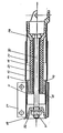
- One section of an inner pipe 12 projects into an outer pipe 11 and another section protrudes from the outer pipe.
- the protruding part of the inner tube has an outer diameter that is larger than the inner diameter of the outer tube.
- the transition 13 between the two zones is conical.
- an end pipe 17 is inserted into the inner pipe 12.
- the part of the inner tube 12 protruding from the outer tube 11 is in contact with the conical transition 13.
- a reinforcement 14 is arranged, which ensures that the outer tube 11 is expanded in the event of a load.
- This reinforcement 14 has a bottom 15.
- Elastic material 16 is arranged in the between this base 15 and the impact shield attachment 18 attached to the end pipe 17.
- the tubes 11, 12 and 17 are clamped together by a screw 20, the screw 20 lying in the imaginary tube axis and being fastened in the impact rod fastening 18 and in the end part 19 of the outer tube 11 by means of nut 21 and washer 22.
- a clamping sleeve 23 acting on the screw head presses against the outer pipe 11 via the reinforcement 14 and the inner pipe 12.
- a connecting plate 24 is arranged on the outer pipe 11 for attaching the impact damper to the car construction.
Claims (5)
- Amortisseur de choc pour véhicules automobiles, comportant un tube extérieur (11), un tube intérieur (12) qui sort partiellement de ce tube extérieur et présente, dans sa portion tubulaire sortie, un diamètre extérieur supérieur au diamètre intérieur du tube extérieur, et comportant aussi un amortisseur élastique de heurt qui est placé dans le tube intérieur et qui, en cas de choc, intervient avant que le tube intérieur, -qui peut coulisser dans le tube extérieur, déforme plastiquement ce tube extérieur, amortisseur caractérisé par le fait que le tube intérieur (12) présente, dans sa portion située à l'extérieur, un tube d'extrémité (17) qui peut coulisser dans le tube intérieur et se tient, extérieurement, au-delà du tube intérieur, par le fait que ce tube intérieur (12) est obturé, à sa portion oui se trouve dans le tube extérieur (12), par un fond (15) et, dans le tube d'extrémité (17), par une fixation (18) de l'amortisseur de choc; et par le fait que,dans l'espace tubulaire libre existant entre eux, un matériau élastique (16) s'appuie contre ces fonds (15,18).
- Amortisseur de choc selon la revendication 1, caractérisé par le fait que dans le tube intérieur (12), à la transition de diamètre (13), est prévu un renfort périphérique (14).
- Amortisseur de choc selon la revendication 2, caractérisé par le fait que le renfort (14) prévu dans le tube intérieur (12) comporte le fond (15).
- Amortisseur de choc selon l'une des revendications 1 à 3, caractérisé par le fait qu'à la transition de diamètre renforcé (13) le tube intérieur (12) et le tube extérieur (11) sont contraints l'un contre l'autre au moyen d'un boulonnage (20).
- Amortisseur de choc selon l'une des revendications 1 à 4, caractérisé par le fait qu'à son extrémité extérieure le tube extérieur (11) présente un fond (19) dans lequel est fixé le boulonnage (20), situé dans l'axe géométrique, qui contraint le tube intérieur (12) contre le tube extérieur (11).
Applications Claiming Priority (2)
| Application Number | Priority Date | Filing Date | Title |
|---|---|---|---|
| AT0239488A ATA239488A (de) | 1988-09-28 | 1988-09-28 | Pralldaempfer fuer kraftfahrzeuge |
| AT2394/88 | 1988-09-28 |
Publications (2)
| Publication Number | Publication Date |
|---|---|
| EP0364432A1 EP0364432A1 (fr) | 1990-04-18 |
| EP0364432B1 true EP0364432B1 (fr) | 1993-02-10 |
Family
ID=3533554
Family Applications (1)
| Application Number | Title | Priority Date | Filing Date |
|---|---|---|---|
| EP89890254A Expired - Lifetime EP0364432B1 (fr) | 1988-09-28 | 1989-09-27 | Amortisseur de choc pour véhicules automobiles |
Country Status (5)
| Country | Link |
|---|---|
| US (1) | US4995486A (fr) |
| EP (1) | EP0364432B1 (fr) |
| AT (1) | ATA239488A (fr) |
| DE (1) | DE58903516D1 (fr) |
| NO (1) | NO893814L (fr) |
Families Citing this family (24)
| Publication number | Priority date | Publication date | Assignee | Title |
|---|---|---|---|---|
| DE4028164A1 (de) * | 1990-07-17 | 1992-01-23 | Schneider Gesenkschmiede | Pralldaempfer |
| DE4028448A1 (de) * | 1990-09-07 | 1992-03-12 | Suspa Compart Ag | Reversibler pralldaempfer, insbesondere fuer kraftfahrzeuge |
| GB9120299D0 (en) * | 1991-09-24 | 1991-11-06 | Latchways Ltd | Load attachment system, and parts fittings therefor |
| JP3144054B2 (ja) * | 1992-05-28 | 2001-03-07 | 株式会社豊田自動織機製作所 | エネルギー吸収部材 |
| DE4345550C5 (de) * | 1992-07-08 | 2008-06-12 | Suspa Holding Gmbh | Pralldämpfer |
| DE4238631C2 (de) * | 1992-11-16 | 2000-05-25 | Euromotive Gmbh | Verfahren zum Montieren einer Stoßverzehrvorrichtung |
| DE4332298C2 (de) * | 1993-09-23 | 1999-04-01 | Audi Ag | Stoßfängerausbildung für Fahrzeuge |
| US5588511A (en) * | 1995-05-15 | 1996-12-31 | Sargent & Lundy | Seismic pipe restraint and method for using the same |
| GB2302578B (en) * | 1995-06-23 | 1999-02-17 | R G Manufacturing Ltd | Nudge bar and energy absorbing device |
| US5870930A (en) * | 1996-09-03 | 1999-02-16 | Means Industries | Steering column assembly |
| BE1010760A3 (fr) * | 1996-11-22 | 1999-01-05 | Solvay | Dispositif anti-choc. |
| DE19654559C2 (de) | 1996-12-27 | 2001-02-08 | Euromotive Gmbh | Stoßverzehrvorrichtung für ein Kraftfahrzeug |
| US6279952B1 (en) * | 2000-01-14 | 2001-08-28 | Trw Inc. | Adaptive collapsible steering column |
| DE10136298B4 (de) * | 2001-07-25 | 2008-08-21 | Zf Boge Elastmetall Gmbh | Pralldämpfer |
| US6876222B2 (en) * | 2002-11-12 | 2005-04-05 | Siemens Westinghouse Power Corporation | Automated stator insulation flaw inspection tool and method of operation |
| DE10317226B4 (de) * | 2003-04-15 | 2006-01-12 | Dr.Ing.H.C. F. Porsche Ag | Pralldämpfer für einen Aufbau eines Kraftfahrzeugs |
| US7025686B1 (en) * | 2003-06-04 | 2006-04-11 | Torque-Traction Technologies, Inc. | Axially collapsible driveshaft assembly |
| DE202005005488U1 (de) * | 2005-04-07 | 2006-09-07 | Dura Automotive Gmbh | Vorrichtung zur Aufnahme von Aufprallenergie |
| DE102005043708A1 (de) * | 2005-09-14 | 2007-03-22 | GM Global Technology Operations, Inc., Detroit | Vorrichtung zur Aufpralldämpfung |
| DE102007005517B4 (de) * | 2007-02-03 | 2010-09-30 | Ise Automotive Gmbh | Überrollschutzsystem für Kraftfahrzeuge mit einem aktiv aufstellbaren Überrollkörper mit integriertem Deformationselement |
| CN100557262C (zh) * | 2008-06-30 | 2009-11-04 | 哈尔滨工业大学 | 组合式缓冲器 |
| EP2295305B2 (fr) * | 2009-09-15 | 2017-06-07 | Voith Patent GmbH | Dispositif de déformation d'énergie, notamment sous la forme d'une sécurité contre les chocs pour un véhicule sur rails |
| US8584819B2 (en) * | 2011-02-04 | 2013-11-19 | David S. Bettinger | Re-stabilized impact strut |
| US9637076B2 (en) * | 2014-09-03 | 2017-05-02 | Ford Global Technologies, Llc | Energy absorbing device for bumper assembly |
Family Cites Families (13)
| Publication number | Priority date | Publication date | Assignee | Title |
|---|---|---|---|---|
| US2251347A (en) * | 1938-12-31 | 1941-08-05 | Clark Equipment Co | Rail car |
| US3186664A (en) * | 1961-01-19 | 1965-06-01 | United States Steel Corp | Yielding anchorage |
| US3482653A (en) * | 1966-08-25 | 1969-12-09 | Nissan Motor | Shock absorbing device |
| US3398812A (en) * | 1966-09-07 | 1968-08-27 | Gerald H. Peterson | Kinetic energy absorber |
| JPS496332B1 (fr) * | 1969-09-10 | 1974-02-13 | ||
| DE2129138A1 (de) * | 1971-06-11 | 1972-12-14 | Wilhelm Karmann GmbH, 4500 Osnabrück | Schutzvorrichtung zur Energieabsorbierung insbesondere für Kraftfahrzeuge |
| DE2164894C3 (de) * | 1971-12-28 | 1974-08-22 | Hoesch Werke Ag, 4600 Dortmund | Energieverzehrendes Stoßdampfungselelement, insbesondere für Kraftfahrzeuge |
| DE2201952C3 (de) * | 1972-01-15 | 1974-08-08 | Hoesch Werke Ag, 4600 Dortmund | Stoßdämpfer, insbesondere für Kraftfahrzeuge |
| GB1419698A (fr) * | 1972-04-19 | 1976-01-07 | ||
| DE2262293C3 (de) * | 1972-12-20 | 1980-12-04 | Dr.Ing.H.C. F. Porsche Ag, 7000 Stuttgart | Stoßenergie absorbierendes Deformationselement für Kraftfahrzeuge, insbesondere Personenkraftwagen |
| DE2441557A1 (de) * | 1974-08-30 | 1976-03-11 | Messerschmitt Boelkow Blohm | Anordnung zur abstuetzung eines stossfaengers |
| DE2460598A1 (de) * | 1974-12-20 | 1976-06-24 | Nissan Motor | Stossdaempfungsvorrichtung |
| DE2825460A1 (de) * | 1977-06-16 | 1979-01-04 | Volvo Ab | Energieabsorber, insbesondere fuer motorfahrzeuge |
-
1988
- 1988-09-28 AT AT0239488A patent/ATA239488A/de not_active Application Discontinuation
-
1989
- 1989-09-26 NO NO89893814A patent/NO893814L/no unknown
- 1989-09-27 EP EP89890254A patent/EP0364432B1/fr not_active Expired - Lifetime
- 1989-09-27 DE DE8989890254T patent/DE58903516D1/de not_active Expired - Fee Related
- 1989-09-28 US US07/414,143 patent/US4995486A/en not_active Expired - Fee Related
Also Published As
| Publication number | Publication date |
|---|---|
| US4995486A (en) | 1991-02-26 |
| EP0364432A1 (fr) | 1990-04-18 |
| NO893814L (no) | 1990-03-29 |
| DE58903516D1 (de) | 1993-03-25 |
| NO893814D0 (no) | 1989-09-26 |
| ATA239488A (de) | 1991-04-15 |
Similar Documents
| Publication | Publication Date | Title |
|---|---|---|
| EP0364432B1 (fr) | Amortisseur de choc pour véhicules automobiles | |
| DE3833048C2 (de) | Stoßfänger für Kraftfahrzeuge, insbesondere Personenkraftwagen | |
| EP0473955B1 (fr) | Dispositif d'amortissement de chocs, particulièrement pour véhicules | |
| DE2938927C2 (fr) | ||
| DE4345550C2 (de) | Pralldämpfer | |
| DE19745656C2 (de) | Pralldämpfer für ein Kraftfahrzeug | |
| DE19717473B4 (de) | Energieabsorberelement | |
| DE19616944B4 (de) | Aufpralldämpfer | |
| DE3711692A1 (de) | Stossfaengeranordnung fuer fahrzeuge | |
| DE19700022A1 (de) | Stoßfängeranordnung für Kraftfahrzeuge | |
| DE19627061C2 (de) | Deformationselement | |
| DE19727931C2 (de) | Pralldämpfer | |
| DE19745651C2 (de) | Pralldämpfer für ein Kraftfahrzeug | |
| DE3617099C2 (fr) | ||
| DE602004002469T2 (de) | Stossdämpfender anschlag für ein kraftfahrzeug | |
| DE4300284C2 (de) | Pralldämpfer | |
| DE2215921A1 (de) | Hydraulischer stossdaempfer | |
| DE2422479A1 (de) | Pralldaempfer mit kraftbegrenzung | |
| DE19832114B4 (de) | Pralldämpfer für Kraftfahrzeuge | |
| DE19649247A1 (de) | Kolbenstange mit wenigstens einem Anschlußzapfen | |
| EP2313293B1 (fr) | Élément absorbant l'énergie générée lors d'une collision | |
| DE4127381C2 (de) | Deformationselement, insbesondere für ein Kraftfahrzeug | |
| EP1398229B1 (fr) | Dispositif d'essuie-glace, en particulier pour un véhicule | |
| DE1530207C3 (de) | Hydraulisch gedämpfte Stoßaufnahmevorrichtung für Eisenbahnwagen | |
| DE3344516A1 (de) | Stossfaenger |
Legal Events
| Date | Code | Title | Description |
|---|---|---|---|
| PUAI | Public reference made under article 153(3) epc to a published international application that has entered the european phase |
Free format text: ORIGINAL CODE: 0009012 |
|
| 17P | Request for examination filed |
Effective date: 19890928 |
|
| AK | Designated contracting states |
Kind code of ref document: A1 Designated state(s): BE CH DE ES FR GB IT LI NL SE |
|
| 17Q | First examination report despatched |
Effective date: 19920529 |
|
| GRAA | (expected) grant |
Free format text: ORIGINAL CODE: 0009210 |
|
| AK | Designated contracting states |
Kind code of ref document: B1 Designated state(s): DE FR GB IT NL SE |
|
| PG25 | Lapsed in a contracting state [announced via postgrant information from national office to epo] |
Ref country code: SE Effective date: 19930210 Ref country code: NL Effective date: 19930210 |
|
| ET | Fr: translation filed | ||
| ITF | It: translation for a ep patent filed |
Owner name: BARZANO' E ZANARDO MILANO S.P.A. |
|
| GBT | Gb: translation of ep patent filed (gb section 77(6)(a)/1977) |
Effective date: 19930215 |
|
| REF | Corresponds to: |
Ref document number: 58903516 Country of ref document: DE Date of ref document: 19930325 |
|
| NLV1 | Nl: lapsed or annulled due to failure to fulfill the requirements of art. 29p and 29m of the patents act | ||
| PGFP | Annual fee paid to national office [announced via postgrant information from national office to epo] |
Ref country code: FR Payment date: 19930812 Year of fee payment: 5 |
|
| PGFP | Annual fee paid to national office [announced via postgrant information from national office to epo] |
Ref country code: GB Payment date: 19930816 Year of fee payment: 5 |
|
| PLBE | No opposition filed within time limit |
Free format text: ORIGINAL CODE: 0009261 |
|
| STAA | Information on the status of an ep patent application or granted ep patent |
Free format text: STATUS: NO OPPOSITION FILED WITHIN TIME LIMIT |
|
| 26N | No opposition filed | ||
| PG25 | Lapsed in a contracting state [announced via postgrant information from national office to epo] |
Ref country code: GB Effective date: 19940927 |
|
| PGFP | Annual fee paid to national office [announced via postgrant information from national office to epo] |
Ref country code: DE Payment date: 19940929 Year of fee payment: 6 |
|
| GBPC | Gb: european patent ceased through non-payment of renewal fee |
Effective date: 19940927 |
|
| PG25 | Lapsed in a contracting state [announced via postgrant information from national office to epo] |
Ref country code: FR Effective date: 19950531 |
|
| REG | Reference to a national code |
Ref country code: FR Ref legal event code: ST |
|
| PG25 | Lapsed in a contracting state [announced via postgrant information from national office to epo] |
Ref country code: DE Effective date: 19960601 |
|
| PG25 | Lapsed in a contracting state [announced via postgrant information from national office to epo] |
Ref country code: IT Free format text: LAPSE BECAUSE OF NON-PAYMENT OF DUE FEES;WARNING: LAPSES OF ITALIAN PATENTS WITH EFFECTIVE DATE BEFORE 2007 MAY HAVE OCCURRED AT ANY TIME BEFORE 2007. THE CORRECT EFFECTIVE DATE MAY BE DIFFERENT FROM THE ONE RECORDED. Effective date: 20050927 |