EP0363682A2 - Dispositif de codage de signal vidéo - Google Patents
Dispositif de codage de signal vidéo Download PDFInfo
- Publication number
- EP0363682A2 EP0363682A2 EP19890117196 EP89117196A EP0363682A2 EP 0363682 A2 EP0363682 A2 EP 0363682A2 EP 19890117196 EP19890117196 EP 19890117196 EP 89117196 A EP89117196 A EP 89117196A EP 0363682 A2 EP0363682 A2 EP 0363682A2
- Authority
- EP
- European Patent Office
- Prior art keywords
- block
- threshold value
- buffer memory
- fill level
- quantization
- Prior art date
- Legal status (The legal status is an assumption and is not a legal conclusion. Google has not performed a legal analysis and makes no representation as to the accuracy of the status listed.)
- Ceased
Links
Images

Classifications
-
- H—ELECTRICITY
- H04—ELECTRIC COMMUNICATION TECHNIQUE
- H04N—PICTORIAL COMMUNICATION, e.g. TELEVISION
- H04N19/00—Methods or arrangements for coding, decoding, compressing or decompressing digital video signals
- H04N19/50—Methods or arrangements for coding, decoding, compressing or decompressing digital video signals using predictive coding
- H04N19/59—Methods or arrangements for coding, decoding, compressing or decompressing digital video signals using predictive coding involving spatial sub-sampling or interpolation, e.g. alteration of picture size or resolution
-
- H—ELECTRICITY
- H04—ELECTRIC COMMUNICATION TECHNIQUE
- H04N—PICTORIAL COMMUNICATION, e.g. TELEVISION
- H04N19/00—Methods or arrangements for coding, decoding, compressing or decompressing digital video signals
- H04N19/10—Methods or arrangements for coding, decoding, compressing or decompressing digital video signals using adaptive coding
- H04N19/102—Methods or arrangements for coding, decoding, compressing or decompressing digital video signals using adaptive coding characterised by the element, parameter or selection affected or controlled by the adaptive coding
- H04N19/124—Quantisation
-
- H—ELECTRICITY
- H04—ELECTRIC COMMUNICATION TECHNIQUE
- H04N—PICTORIAL COMMUNICATION, e.g. TELEVISION
- H04N19/00—Methods or arrangements for coding, decoding, compressing or decompressing digital video signals
- H04N19/10—Methods or arrangements for coding, decoding, compressing or decompressing digital video signals using adaptive coding
- H04N19/134—Methods or arrangements for coding, decoding, compressing or decompressing digital video signals using adaptive coding characterised by the element, parameter or criterion affecting or controlling the adaptive coding
- H04N19/146—Data rate or code amount at the encoder output
- H04N19/152—Data rate or code amount at the encoder output by measuring the fullness of the transmission buffer
-
- H—ELECTRICITY
- H04—ELECTRIC COMMUNICATION TECHNIQUE
- H04N—PICTORIAL COMMUNICATION, e.g. TELEVISION
- H04N19/00—Methods or arrangements for coding, decoding, compressing or decompressing digital video signals
- H04N19/50—Methods or arrangements for coding, decoding, compressing or decompressing digital video signals using predictive coding
- H04N19/587—Methods or arrangements for coding, decoding, compressing or decompressing digital video signals using predictive coding involving temporal sub-sampling or interpolation, e.g. decimation or subsequent interpolation of pictures in a video sequence
-
- H—ELECTRICITY
- H04—ELECTRIC COMMUNICATION TECHNIQUE
- H04N—PICTORIAL COMMUNICATION, e.g. TELEVISION
- H04N19/00—Methods or arrangements for coding, decoding, compressing or decompressing digital video signals
- H04N19/50—Methods or arrangements for coding, decoding, compressing or decompressing digital video signals using predictive coding
Definitions
- the invention relates to a device for coding a video signal, in particular according to the DPCM method, according to the preamble of the main claim.
- the data to be transmitted are non-uniform. For example, much more data is required to transmit a detailed image section than for a large image section.
- interframe coding the amount of data that arises per unit of time is also dependent on the presence of movement.
- a buffer memory is therefore provided, with the aid of which a non-uniform data stream is converted into a uniform data stream.
- the known devices use quantization according to the fill level of the buffer memory controlled.
- the object of the present invention is to provide a device for coding a video signal, in particular according to the DPCM method, in which controlling the coding as a function of the fill level of the buffer memory ensures the highest possible transmission quality.
- the device according to the invention with the characterizing features of the main claim has the advantage that the data reduction rate can be adapted in a wide range to the properties of the image to be transmitted in each case.
- the threshold value is kept at a minimum value in a lower area of the fill level and the quantization characteristic curve becomes coarser with increasing fill level, while in an upper one Range of the fill level with a rough quantization curve the threshold value increases with increasing fill level.
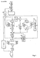
- the circuit arrangement shown in FIG. 1 represents a transmission device for a narrowband videophone, the output signals of a video camera 1 being converted analog / digital and then encoded using data-reducing methods in such a way that they are transmitted to a receiver via a narrowband channel 2 can.
- the related to the 1 refer to the so-called CIF resolution of 360 x 288 picture elements for the luminance component and of 180 x 144 picture elements for the chrominance components U, V.
- the capacity of the transmission channel 2 is 64000 bit / s.
- the following known methods essentially contribute to the reduction of the data stream: reduction of the motion resolution (only every third image is transmitted), DPCM (interframe), discrete cosine transformation (DCT), adaptive quantization and entropy coding.
- reduction of the motion resolution only every third image is transmitted
- DPCM interframe
- DCT discrete cosine transformation
- a switchover to an intra-frame DPCM is also provided.
- the coding of the luminance signal is explained below using individual functional units, while the coding of the chrominance signals U, V is only represented by a functional unit 3, since this coding is carried out in a manner similar to the coding of the luminance signal Y.
- the output signals of the analog / digital converter 4 are alternately written image-wise into one of two image memories 6, 7 via a changeover switch 5.
- the signals After temporary storage for time adjustment in a FIFO memory 9, the signals arrive at a subtraction circuit 10, which is part of a prediction loop 11.
- the output signals of the subtraction circuit - that is mostly the differences between the signal generated by the camera and the Signal of a stored image - transformed block by block.
- a block each includes n picture elements from n successive lines, which represent a partial area of the picture of nxn picture elements.
- blocks of 8 x 8 picture elements are suggested.
- blocks of 16 x 16 picture elements for the luminance and 8 x 8 picture elements each for the chrominance were found to be favorable.
- the discrete cosine transformation determines coefficients for a block of nxn picture elements, which correspond to the direct component of the signal (i.e. the average brightness), the amplitude of a fundamental wave, the period of which corresponds to twice the block length, and the amplitudes of the harmonics.
- the amplitude of the harmonics decreases more or less strongly with the atomic number of the respective harmonic, so that for a large proportion of the blocks only the direct component, the fundamental and / or a few harmonics are to be transmitted.
- the output signals of the circuit 12 are fed to a controllable quantizer 13, which can carry out a coarser or finer quantization depending on a supplied control signal.
- the quantized signals are then fed within the prediction loop 11 to a circuit 14 for inverse discrete cosine transformation and are read into additional image memories 16, 17 via an adder circuit 15.
- the image memories 16, 17 represent a prediction memory. Two image memories are used to enable reading while new signals are being written. To do this, the Switch 18, 19 controlled accordingly.
- the signals read out from the prediction memory 16, 17 reach the subtraction circuit 10 and, via a FIFO memory 20 used for time adjustment, the adder circuit 15.
- a motion estimator 21 which generates a motion vector for a block by comparing successive images.
- the motion estimator 21 can be supplied with corresponding signals from the image memories 6 and 7.
- the signals to be transmitted and on the other hand signals from the prediction memory 16, 17 can be supplied.
- the motion vectors are fed to an addressing logic 22, so that when the signals are read block by block from the prediction memory 16, 17, a shift in the content of the respective block caused by movement between the stored and the current picture is taken into account.
- the output signals of the quantizer 13, the encoder 3 for the chrominance signals U, V and the output signals of the motion estimator 21 are fed to an entropy encoder 23, in which incoming code words are converted into shorter or longer outgoing code words according to the frequency of their occurrence.
- a buffer memory 24 is provided in front of the transmission link 2, which has, for example, the capacity of an image.
- a signal is taken from the buffer memory 24 which corresponds to the fill level. This can be, for example, in the difference between the write-in and read-out addresses when using a read / write memory (RAM). If this difference is 0, the memory is empty, while a difference corresponding to the buffer size means a filled memory.
- This signal is fed to a signal processor 25 which, according to algorithms which are described in connection with FIGS. 2 and 3, derives the signals T for the threshold value and D for controlling the quantization characteristic.
- the signal T is fed to the motion estimator 21, in which changes are determined in one block in each case in relation to a comparable block of a previous image in order to estimate movements present in the image.
- the sum of the absolute differences to the mean in the respective block can be obtained as a measure of the changes. This is relatively easy to calculate, which contributes to a reduction in the technical outlay for a device according to the invention.
- the variance in the block can also be calculated as a measure of the changes in the block, which is more complex, but gives a better description of the structural integrity. If necessary, the performance in the block can also serve as a measure of the changes. If these changes are very small, it is assumed that there has been no change to the previous picture and that coding of the current blocks is not necessary. For such a block, the motion estimator 21 therefore sends a signal to the subtracting circuit 10, which means that only the signal circulates in the DPCM loop 11.
- the size of the difference or the extent of changes which prevent coding of the respective block is supplied to the motion estimator 21 as a threshold value T. If the threshold value T is large, only those blocks are coded whose content differs greatly from the comparable block of the previous picture. With a small T, coding takes place even with slight deviations.
- the signal D represents a scaling factor and brings about a finer or coarser characteristic curve of the quantizer 13.
- a quantization circuit 31 is provided in the quantizer 13, which has a characteristic curve with the finest gradation that is to be used in the device according to the invention.
- This quantization circuit 31 is preceded by a multiplier circuit 32, with which the output signals of the circuit 12 for discrete cosine transformation are multiplied by the reciprocal of D.
- the reciprocal value is formed in a read-only memory 33.
- the scaling factor With a small D, the entire modulation range of the quantization circuit 31 is then used, so that a fine quantization occurs, while with a larger D, the amplitude of the signals supplied to the quantization circuit 31 is smaller and only a partial area of the characteristic curve is used.
- the scaling factor In order to be able to carry out a corresponding decoding, the scaling factor must also be effective in the receiver. B. in that it is transmitted together with the useful signals, for which purpose the signal D is supplied to the en
- D has its maximum value D max
- T increases from the minimum value T min to the maximum value T max . Both maximum values are reached at the upper limit b o of the control range. If the fill level should then continue to increase, an interruption in the transfer of data to the buffer memory 24 (FIG. 1) is required.
- D i the scaling factor for the ith block described above
- D i-1 is the scaling factor for the (i-1) th block b i the level to the i-th block
- b i-1 the level of the (i-1) first block
- c a parameter and D cor is a function at a medium level has a minimum and increases for larger and smaller fill levels.
- the basic course of the function D cor as a function of b is shown in FIG. 3. From a medium fill level, at which practically no additional influence on the amount of data supplied to the buffer memory is required, D cor initially only increases gradually in order to become steeper with larger deviations (from the medium level), since a faster reaction is required here. From a certain deviation, D cor reaches a maximum value to which it is then limited.
- the function D cor can be stored in the form of a table in a memory, which saves a repeated calculation for the respective values of b.
- the scaling factor D can be transmitted together with the useful signals.
- it is also possible to calculate the scaling factor D in the receiver from the fill level of a buffer memory which is arranged at the input of a receiver. 4 serves to explain this development of the invention, for which purpose only the parts of a receiver necessary for this are shown.
- the transmitted signals are fed via an input 41 to a digital signal processor 42 known per se, which has an internal memory 43.
- This internal memory 43 converts the incoming uniform data flow into a non-uniform data flow which is adapted to the requirements of the subsequent decoding.
- the scaling factor D can be separated from the incoming signals with the aid of the digital signal processor 42 if it is transmitted with them. In order to achieve better utilization of the transmission channel, however, the scaling factor D can also be determined from the fill level of the internal memory 43, for which purpose a corresponding program is provided in the digital signal processor 42. However, if the computing capacity of the digital Signal processor should already be exhausted by other programs, the scaling factor D can also be determined from the fill level with the aid of another suitable arithmetic circuit 44.
- the useful signals are sent from the digital signal processor 42 via a buffer 45 to a multiplier 46, which is also supplied with the scaling factor D.
- the scaling carried out with the aid of the multiplier circuit 32 (FIG. 1) is thus undone.
- a subsequent circuit 47 further steps for decoding the received signals take place.
- the digital video signals thus generated are fed via a digital / analog converter 48 to a display device 49 shown as a picture tube.
Applications Claiming Priority (2)
| Application Number | Priority Date | Filing Date | Title |
|---|---|---|---|
| DE3834476 | 1988-10-11 | ||
| DE3834476A DE3834476A1 (de) | 1988-10-11 | 1988-10-11 | Einrichtung zur codierung eines videosignals |
Publications (2)
| Publication Number | Publication Date |
|---|---|
| EP0363682A2 true EP0363682A2 (fr) | 1990-04-18 |
| EP0363682A3 EP0363682A3 (fr) | 1990-08-29 |
Family
ID=6364795
Family Applications (1)
| Application Number | Title | Priority Date | Filing Date |
|---|---|---|---|
| EP89117196A Ceased EP0363682A3 (fr) | 1988-10-11 | 1989-09-18 | Dispositif de codage de signal vidéo |
Country Status (2)
| Country | Link |
|---|---|
| EP (1) | EP0363682A3 (fr) |
| DE (1) | DE3834476A1 (fr) |
Cited By (1)
| Publication number | Priority date | Publication date | Assignee | Title |
|---|---|---|---|---|
| EP0703711A2 (fr) | 1994-09-22 | 1996-03-27 | Philips Patentverwaltung GmbH | Codeur à segmentation d'un signal vidéo |
Families Citing this family (1)
| Publication number | Priority date | Publication date | Assignee | Title |
|---|---|---|---|---|
| DE19718802C2 (de) * | 1997-05-03 | 1999-04-08 | Inst Rundfunktechnik Gmbh | Verfahren zum Analysieren von bildinhaltsabhängig qualitätsmindernden Eigenschaften eines bitratenreduzierenden digitalen Videosystems |
Citations (2)
| Publication number | Priority date | Publication date | Assignee | Title |
|---|---|---|---|---|
| US4562468A (en) * | 1982-05-14 | 1985-12-31 | Nec Corporation | Adaptive predictive coding apparatus of television signal |
| GB2173067A (en) * | 1985-03-20 | 1986-10-01 | Nec Corp | Method and arrangement of coding digital image signals utilizing interframe correlation |
-
1988
- 1988-10-11 DE DE3834476A patent/DE3834476A1/de not_active Withdrawn
-
1989
- 1989-09-18 EP EP89117196A patent/EP0363682A3/fr not_active Ceased
Patent Citations (2)
| Publication number | Priority date | Publication date | Assignee | Title |
|---|---|---|---|---|
| US4562468A (en) * | 1982-05-14 | 1985-12-31 | Nec Corporation | Adaptive predictive coding apparatus of television signal |
| GB2173067A (en) * | 1985-03-20 | 1986-10-01 | Nec Corp | Method and arrangement of coding digital image signals utilizing interframe correlation |
Cited By (2)
| Publication number | Priority date | Publication date | Assignee | Title |
|---|---|---|---|---|
| EP0703711A2 (fr) | 1994-09-22 | 1996-03-27 | Philips Patentverwaltung GmbH | Codeur à segmentation d'un signal vidéo |
| US6147627A (en) * | 1994-09-22 | 2000-11-14 | U.S. Philips Corporation | Coder for segmented coding of an input signal using controllable quantization based on quantization step size and buffer fullness |
Also Published As
| Publication number | Publication date |
|---|---|
| DE3834476A1 (de) | 1990-04-12 |
| EP0363682A3 (fr) | 1990-08-29 |
Similar Documents
| Publication | Publication Date | Title |
|---|---|---|
| DE69435000T2 (de) | Bildkodierungsvorrichtung | |
| EP0201679B1 (fr) | Procédé de réduction de données d'images pour des signaux de télévision numériques | |
| DE4343211B4 (de) | Adaptives Bildkompressionsverfahren und adaptive Bildkompressionsvorrichtung | |
| DE69815922T2 (de) | Verfahren und Vorrichtung zur prädiktiven Bildkodierung und -dekodierung | |
| DE69837003T2 (de) | Vorrichtung und verfahren zur optimierung der bitratensteurung in einem kodiersystem | |
| DE69738264T2 (de) | Videokodierungs- und Videodekodierungsvorrichtung | |
| DE69734831T2 (de) | Adaptive steuerung der datenrate für digitale videokompression | |
| DE69434667T2 (de) | Adaptives codierungs-decodierungsverfahren mit variabler länge für bilddaten | |
| DE69233411T2 (de) | Verfahren und Einrichtung zur Kompression von sich bewegenden Videobildern mit adaptiver Bitzuordnung und Quantisierung | |
| DE69822607T2 (de) | Nichtlinearer quantisierer für videokodierung | |
| DE60001896T2 (de) | Quantisierer für videokompression | |
| EP0703711B1 (fr) | Codeur à segmentation d'un signal vidéo | |
| DE69636273T2 (de) | Bewegtbildcodiervorrichtung, Bewegtbilddecodiervorrichtung und Bewegtbildcodier-/-Decodiervorrichtung | |
| DE3926154A1 (de) | Signalverarbeitungssystem | |
| EP0363682A2 (fr) | Dispositif de codage de signal vidéo | |
| EP0920216A1 (fr) | Procédé et dispositif pour le codage et le décodage d'une séquence d'images | |
| DE3835368A1 (de) | Schaltungsanordnung zum auslesen von daten aus einem bildspeicher | |
| DE10156851C1 (de) | Verfahren und Vorrichtung zur Bildkompression | |
| DE102004029086B4 (de) | Verfahren zum Entblocken und Umcodieren eines Medienstroms | |
| DE2703854A1 (de) | Bilduebertragungsanlage | |
| DE3839642A1 (de) | Einrichtung zur codierung von videosignalen | |
| DE19743203C2 (de) | Pufferdatensteuerungsverfahren und Schaltkreis in einem Bildkompressionssystem | |
| WO1999012355A1 (fr) | Procede pour comprimer des informations image | |
| DE10046807C2 (de) | Verfahren und Vorrichtung zur Bildkompression | |
| DE69810476T2 (de) | Abstimmungsverfahren für videobildbände und filtervorrichtung |
Legal Events
| Date | Code | Title | Description |
|---|---|---|---|
| PUAI | Public reference made under article 153(3) epc to a published international application that has entered the european phase |
Free format text: ORIGINAL CODE: 0009012 |
|
| AK | Designated contracting states |
Kind code of ref document: A2 Designated state(s): AT CH DE ES FR GB IT LI SE |
|
| PUAL | Search report despatched |
Free format text: ORIGINAL CODE: 0009013 |
|
| AK | Designated contracting states |
Kind code of ref document: A3 Designated state(s): AT CH DE ES FR GB IT LI SE |
|
| 17P | Request for examination filed |
Effective date: 19900725 |
|
| RAP3 | Party data changed (applicant data changed or rights of an application transferred) |
Owner name: ROBERT BOSCH GMBH |
|
| 17Q | First examination report despatched |
Effective date: 19920522 |
|
| STAA | Information on the status of an ep patent application or granted ep patent |
Free format text: STATUS: THE APPLICATION HAS BEEN REFUSED |
|
| 18R | Application refused |
Effective date: 19920809 |