EP0363682A2 - Video signal encoding device - Google Patents
Video signal encoding device Download PDFInfo
- Publication number
- EP0363682A2 EP0363682A2 EP19890117196 EP89117196A EP0363682A2 EP 0363682 A2 EP0363682 A2 EP 0363682A2 EP 19890117196 EP19890117196 EP 19890117196 EP 89117196 A EP89117196 A EP 89117196A EP 0363682 A2 EP0363682 A2 EP 0363682A2
- Authority
- EP
- European Patent Office
- Prior art keywords
- block
- threshold value
- buffer memory
- fill level
- quantization
- Prior art date
- Legal status (The legal status is an assumption and is not a legal conclusion. Google has not performed a legal analysis and makes no representation as to the accuracy of the status listed.)
- Ceased
Links
Images

Classifications
-
- H—ELECTRICITY
- H04—ELECTRIC COMMUNICATION TECHNIQUE
- H04N—PICTORIAL COMMUNICATION, e.g. TELEVISION
- H04N19/00—Methods or arrangements for coding, decoding, compressing or decompressing digital video signals
- H04N19/50—Methods or arrangements for coding, decoding, compressing or decompressing digital video signals using predictive coding
- H04N19/59—Methods or arrangements for coding, decoding, compressing or decompressing digital video signals using predictive coding involving spatial sub-sampling or interpolation, e.g. alteration of picture size or resolution
-
- H—ELECTRICITY
- H04—ELECTRIC COMMUNICATION TECHNIQUE
- H04N—PICTORIAL COMMUNICATION, e.g. TELEVISION
- H04N19/00—Methods or arrangements for coding, decoding, compressing or decompressing digital video signals
- H04N19/10—Methods or arrangements for coding, decoding, compressing or decompressing digital video signals using adaptive coding
- H04N19/102—Methods or arrangements for coding, decoding, compressing or decompressing digital video signals using adaptive coding characterised by the element, parameter or selection affected or controlled by the adaptive coding
- H04N19/124—Quantisation
-
- H—ELECTRICITY
- H04—ELECTRIC COMMUNICATION TECHNIQUE
- H04N—PICTORIAL COMMUNICATION, e.g. TELEVISION
- H04N19/00—Methods or arrangements for coding, decoding, compressing or decompressing digital video signals
- H04N19/10—Methods or arrangements for coding, decoding, compressing or decompressing digital video signals using adaptive coding
- H04N19/134—Methods or arrangements for coding, decoding, compressing or decompressing digital video signals using adaptive coding characterised by the element, parameter or criterion affecting or controlling the adaptive coding
- H04N19/146—Data rate or code amount at the encoder output
- H04N19/152—Data rate or code amount at the encoder output by measuring the fullness of the transmission buffer
-
- H—ELECTRICITY
- H04—ELECTRIC COMMUNICATION TECHNIQUE
- H04N—PICTORIAL COMMUNICATION, e.g. TELEVISION
- H04N19/00—Methods or arrangements for coding, decoding, compressing or decompressing digital video signals
- H04N19/50—Methods or arrangements for coding, decoding, compressing or decompressing digital video signals using predictive coding
- H04N19/587—Methods or arrangements for coding, decoding, compressing or decompressing digital video signals using predictive coding involving temporal sub-sampling or interpolation, e.g. decimation or subsequent interpolation of pictures in a video sequence
-
- H—ELECTRICITY
- H04—ELECTRIC COMMUNICATION TECHNIQUE
- H04N—PICTORIAL COMMUNICATION, e.g. TELEVISION
- H04N19/00—Methods or arrangements for coding, decoding, compressing or decompressing digital video signals
- H04N19/50—Methods or arrangements for coding, decoding, compressing or decompressing digital video signals using predictive coding
Abstract
Description
Die Erfindung geht aus von einer Einrichtung zur Codierung eines Videosignals, insbesondere nach dem DPCM-Verfahren, nach der Gattung des Hauptanspruchs.The invention relates to a device for coding a video signal, in particular according to the DPCM method, according to the preamble of the main claim.
Bei der datenreduzierenden Codierung von Videosignalen fallen die zu übertragenden Daten ungleichförmig an. So werden beispielsweise zur Übertragung eines detailreichen Bildausschnitts wesentlich mehr Daten benötigt, als für einen großflächigen Bildausschnitt. Bei der sogenannten Interframe-Codierung ist die Datenmenge, welche je Zeiteinheit anfällt, außerdem vom Vorliegen von Bewegung abhängig.In the data-reducing coding of video signals, the data to be transmitted are non-uniform. For example, much more data is required to transmit a detailed image section than for a large image section. In the so-called interframe coding, the amount of data that arises per unit of time is also dependent on the presence of movement.
Zur höchstmöglichen Ausnutzung des Übertragungskanals ist jedoch bei der Übertragung eine Datenrate erforderlich, die der Kanalkapazität entspricht - also konstant ist.In order to make maximum use of the transmission channel, however, a data rate that corresponds to the channel capacity is required for the transmission - that is, it is constant.
Bei bekannten Schmalband-Bildübertragungseinrichtungen ist daher ein Pufferspeicher vorgesehen, mit dessen Hilfe ein ungleichförmiger Datenstrom in einen gleichförmigen Datenstrom umgewandelt wird. Um ein Überlaufen oder ein Leerlaufen des Pufferspeichers zu vermeiden, wird bei den bekannten Einrichtungen die Quantisierung nach dem Füllstand des Pufferspeichers gesteuert.In known narrowband image transmission devices, a buffer memory is therefore provided, with the aid of which a non-uniform data stream is converted into a uniform data stream. In order to prevent the buffer memory from overflowing or emptying, the known devices use quantization according to the fill level of the buffer memory controlled.
Aufgabe der vorliegenden Erfindung ist es, eine Einrichtung zur Codierung eines Videosignals insbesondere nach dem DPCM-Verfahren anzugeben, bei welchem eine Steuerung der Codierung in Abhängigkeit vom Füllstand des Pufferspeichers eine möglichst hohe Übertragungsqualität gewährleistet. Die erfindungsgemäße Einrichtung mit den kennzeichnenden Merkmalen des Hauptanspruchs hat den Vorteil, daß die Datenreduktionsrate in einem weiten Bereich an die Eigenschaften des jeweils zu übertragenden Bildes angepaßt werden kann.The object of the present invention is to provide a device for coding a video signal, in particular according to the DPCM method, in which controlling the coding as a function of the fill level of the buffer memory ensures the highest possible transmission quality. The device according to the invention with the characterizing features of the main claim has the advantage that the data reduction rate can be adapted in a wide range to the properties of the image to be transmitted in each case.
Obwohl die Erfindung in erster Linie zur gemeinsamen Anwendung mit DPCM-Verfahren vorgesehen ist, eignet sie sich auch zusammen mit anderen Codierverfahren. Die Anwendung im Zusammenhang mit DPCM-Verfahren ist sowohl bei einer Interframe- als auch bei einer Intraframe-Codierung möglich.Although the invention is primarily intended for joint use with DPCM methods, it is also suitable together with other coding methods. Use in connection with DPCM methods is possible with both interframe and intraframe coding.
Durch die in den Unteransprüchen aufgeführten Maßnahmen sind vorteilhafte Weiterbildungen und Verbesserungen der im Hauptanspruch angegebenen Erfindung möglich.Advantageous further developments and improvements of the invention specified in the main claim are possible through the measures listed in the subclaims.
Einige der Weiterbildungen und Verbesserungen beziehen sich auf die Anwendung der erfindungsgemäßen Einrichtung im Zusammenhang mit einer Intraframe-DPCM, einer diskreten Cosinustransformation sowie einer Bewegungskompensation bei der DPCM. Die erfindungsgemäße Einrichtung als solche und andere Weiterbildungen sind jedoch nicht auf diese Codierungen beschränkt.Some of the developments and improvements relate to the use of the device according to the invention in connection with an intra-frame DPCM, a discrete cosine transformation and a motion compensation in the DPCM. However, the device according to the invention as such and other developments are not limited to these codes.
Insbesondere wird bei einer Weiterbildung der Erfindung in einem unteren Bereich des Füllstandes der Schwellwert auf einem Mindestwert gehalten und die Quantisierungskennlinie mit zunehmendem Füllstand gröber, während in einem oberen Bereich des Füllstandes bei grober Quantisierungskennlinie der Schwellwert mit zunehmendem Füllstand ansteigt.In particular, in a further development of the invention, the threshold value is kept at a minimum value in a lower area of the fill level and the quantization characteristic curve becomes coarser with increasing fill level, while in an upper one Range of the fill level with a rough quantization curve the threshold value increases with increasing fill level.
Hierdurch wird erreicht, daß auch bei hohem Datenanfall möglichst viele Bereiche des Bildes übertragen werden - allerdings mit weniger guter Auflösung. Erst bei einem Datenanfall, bei welchem der Speicher möglicherweise überläuft, werden nur noch diejenigen Bildbereiche übertragen, deren Inhalt stark von dem Bereich des vorangegangenen Bildes abweicht.This ensures that as many areas of the image as possible are transmitted even when there is a large amount of data - but with less good resolution. Only in the event of a data attack, in which the memory may overflow, are only those image areas transferred whose content differs greatly from the area of the previous image.
Ein Ausführungsbeispiel der Erfindung ist in der Zeichnung anhand mehrerer Figuren dargestellt und in der nachfolgenden Beschreibung näher erläutert. Es zeigt:
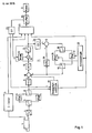
- Fig. 1 ein Blockschaltbild einer Schmalband-Bildübertragungseinrichtung,
- Fig. 2 ein Diagramm zur Darstellung der Abhängigkeit des Schwellwertes und der Quantisierungskennlinie vom Füllstand des Pufferspeichers und
- Fig. 3 ein weiteres Diagramm zur Erläuterung der Abhängigkeit der Quantisierungskennlinie vom Füllstand des Pufferspeichers.
- Fig. 4 als Blockschaltbild Teile eines Empfängers zur Erläuterung einer Weiterbildung der Erfindung.
- 1 is a block diagram of a narrowband image transmission device,
- Fig. 2 is a diagram showing the dependency of the threshold value and the quantization curve on the fill level of the buffer memory and
- 3 shows a further diagram to explain the dependency of the quantization characteristic on the fill level of the buffer memory.
- Fig. 4 shows a block diagram of parts of a receiver to explain a development of the invention.
Die in Fig. 1 dargestellte Schaltungsanordnung stellt eine Sendeeinrichtung für ein Schmalband-Bildtelefon dar, wobei die Ausgangssignale einer Videokamera 1 analog/digital-gewandelt und anschließend unter Anwendung datenreduzierender Verfahren derart codiert werden, daß sie über einen schmalbandigen Kanal 2 zu einem Empfänger übertragen werden können. Die im Zusammenhang mit der Schaltungsanordnung nach Fig. 1 genannten Zahlenangaben beziehen sich auf die sogenannte CIF-Auflösung von 360 x 288 Bildelementen für den Luminanzanteil und von jeweils 180 x 144 Bildelementen für die Chrominanzanteile U, V. Die Kapazität des Übertragungskanals 2 beträgt 64000 Bit/s.The circuit arrangement shown in FIG. 1 represents a transmission device for a narrowband videophone, the output signals of a
Zur Reduzierung des Datenstroms tragen im wesentlichen die folgenden bekannten Verfahren bei: Reduzierung der Bewegungsauflösung (es wird nur jedes dritte Bild übertragen), DPCM (Interframe), diskrete Cosinus-Transformation (DCT), adaptive Quantisierung und Entropie-Codierung. Ferner ist eine Umschaltung auf eine Intraframe-DPCM vorgesehen.The following known methods essentially contribute to the reduction of the data stream: reduction of the motion resolution (only every third image is transmitted), DPCM (interframe), discrete cosine transformation (DCT), adaptive quantization and entropy coding. A switchover to an intra-frame DPCM is also provided.
Die Codierung des Luminanzsignals wird im folgenden anhand einzelner Funktionseinheiten erläutert, während die Codierung der Chrominanzsignale U, V nur durch eine Funktionseinheit 3 dargestellt ist, da diese Codierung in ähnlicher Weise wie die Codierung des Luminanzsignals Y erfolgt.The coding of the luminance signal is explained below using individual functional units, while the coding of the chrominance signals U, V is only represented by a
Die Ausgangssignale des Analog/Digital-Wandlers 4 werden über einen Umschalter 5 bildweise abwechselnd in einen von zwei Bildspeichern 6, 7 eingeschrieben. Durch entsprechende Steuerung eines weiteren Umschalters 8 sowie im einzelnen nicht dargestellte Adressierung beim Auslesen wird jedes dritte Bild aus den Speichern 6, 7 ausgelesen, so daß sich bereits eine Datenreduktion um den Faktor 3 ergibt.The output signals of the analog /
Nach einer Zwischenspeicherung zur Zeitanpassung in einem FIFO-Speicher 9 gelangen die Signale zu einer Subtraktionsschaltung 10, welche Teil einer Prädiktionsschleife 11 ist. In einer Schaltung 12 zur diskreten Cosinus-Transformation werden die Ausgangssignale der Subtraktionsschaltung - also meistens die Differenzen zwischen dem jeweils von der Kamera erzeugten Signal und dem Signal eines gespeicherten Bildes - blockweise transformiert. Zu einem Block gehören jeweils n Bildelemente aus n aufeinanderfolgenden Zeilen, die eine Teilfläche des Bildes von n x n Bildelementen darstellen. Meistens werden Blöcke der Größe 8 x 8 Bildelemente vorgeschlagen. Bei der Realisierung der Erfindung haben sich für die Luminanz Blöcke von 16 x 16 Bildelementen und für die Chrominanz jeweils 8 x 8 Bildelemente große Blöcke als günstig herausgestellt.After temporary storage for time adjustment in a
Da die diskrete Cosinus-Transformation an sich bekannt ist (siehe Ahmed N., Natarajan T. und Rao R.: Discrete Cosine Transform, IEEE Transactions C-23 (1974), Seiten 90 bis 93), sei im folgenden nur kurz erwähnt, daß durch die diskrete Cosinus-Transformation jeweils für einen Block aus n x n Bildelementen Koeffizienten ermittelt werden, welche dem Gleichanteil des Signals (also der mittleren Helligkeit), der Amplitude einer Grundwelle, deren Periode der doppelten Blocklänge entspricht, und den Amplituden der Oberwellen entsprechen. Je nach Bildinhalt nimmt die Amplitude der Oberwellen mit der Ordnungszahl der jeweiligen Oberwelle mehr oder weniger stark ab, so daß für einen großen Anteil der Blöcke nur der Gleichanteil, die Grundwelle und/oder wenige Oberwellen zu übertragen sind.Since the discrete cosine transformation is known per se (see Ahmed N., Natarajan T. and Rao R .: Discrete Cosine Transform, IEEE Transactions C-23 (1974), pages 90 to 93), it is only briefly mentioned below that that the discrete cosine transformation determines coefficients for a block of nxn picture elements, which correspond to the direct component of the signal (i.e. the average brightness), the amplitude of a fundamental wave, the period of which corresponds to twice the block length, and the amplitudes of the harmonics. Depending on the image content, the amplitude of the harmonics decreases more or less strongly with the atomic number of the respective harmonic, so that for a large proportion of the blocks only the direct component, the fundamental and / or a few harmonics are to be transmitted.
Die Ausgangssignale der Schaltung 12 werden einem steuerbaren Quantisierer 13 zugeführt, der in Abhängigkeit von einem zugeführten Steuersignal eine gröbere oder feinere Quantisierung vornehmen kann. Die quantisierten Signale werden dann innerhalb der Prädiktionsschleife 11 einer Schaltung 14 zur inversen diskreten Cosinus-Transformation zugeleitet und über eine Addierschaltung 15 in weitere Bildspeicher 16, 17 eingelesen. Die Bildspeicher 16, 17 stellen einen Prädiktionsspeicher dar. Es werden zwei Bildspeicher verwendet, um ein Lesen zu ermöglichen, während neue Signale eingeschrieben werden. Dazu werden die Umschalter 18, 19 entsprechend gesteuert. Die aus dem Prädiktionsspeicher 16, 17 ausgelesenen Signale gelangen zur Subtraktionsschaltung 10 und über einen zur Zeitanpassung dienenden FIFO-Speicher 20 zur Addierschaltung 15.The output signals of the
Um eine genauere Prädiktion auch bei bewegten Bildern zu erhalten, ist ein Bewegungsschätzer 21 vorgesehen, der durch Vergleich aufeinanderfolgender Bilder jeweils für einen Block einen Bewegungsvektor erzeugt. Dazu können dem Bewegungsschätzer 21 - wie in Fig. 1 dargestellt - entsprechende Signale aus den Bildspeichern 6 und 7 zugeführt werden. Es können jedoch auch einerseits die zu übertragenden Signale und andererseits Signale aus dem Prädiktionsspeicher 16, 17 zugeleitet werden. Die Bewegungsvektoren werden einer Adressierlogik 22 zugeführt, so daß beim blockweisen Lesen der Signale aus dem Prädiktionsspeicher 16, 17 bereits eine durch Bewegung verursachte Verschiebung des Inhalts des jeweiligen Blocks zwischen dem gespeicherten und dem jeweils aktuellen Bild berücksichtigt wird.In order to obtain a more precise prediction even in the case of moving images, a
Die Ausgangssignale des Quantisierers 13, des Coders 3 für die Chrominanzsignale U, V sowie die Ausgangssignale des Bewegungsschätzers 21 werden einem Entropie-Coder 23 zugeführt, bei welchem eingehende Codewörter entsprechend der Häufigkeit ihres Auftretens in kürzere bzw. längere ausgehende Codewörter gewandelt werden.The output signals of the quantizer 13, the
Da die durch die Codierung entstehenden Daten je nach Auftreten von Bewegung und Details im aufgenommenen Bild unregelmäßig anfallen, ist ein Pufferspeicher 24 vor der Übertragungsstrecke 2 vorgesehen, der beispielsweise die Kapazität eines Bildes aufweist.Since the data resulting from the coding occur irregularly depending on the occurrence of movement and details in the recorded image, a
Zur Steuerung des Schwellwertes und der Quantisierungskennlinie wird vom Pufferspeicher 24 ein Signal abgenommen, das dem Füllstand entspricht. Dieses kann beispielsweise in der Differenz zwischen den Einschreib- und Ausleseadressen bei der Verwendung eines Schreib/Lese-Speichers (RAM) sein. Ist diese Differenz gleich 0, ist der Speicher leer, während eine der Puffergröße entsprechende Differenz einen gefüllten Speicher bedeutet. Dieses Signal wird einem Signalprozessor 25 zugeleitet, der nach Algorithmen, die im Zusammenhang mit den Figuren 2 und 3 beschrieben werden, die Signale T für den Schwellwert und D zur Steuerung der Quantisierungskennlinie ableitet. Das Signal T wird dem Bewegungsschätzer 21 zugeführt, in welchem zur Abschätzung von im Bild vorliegenden Bewegungen Veränderungen in jeweils einem Block gegenüber einem vergleichbaren Block eines vorangegangenen Bildes ermittelt werden. Als Maß für die Veränderungen kann die Summe der absoluten Differenzen zum Mittelwert im jeweiligen Block gewonnen werden. Dieses ist relativ einfach zu berechnen, was zu einer Verringerung des technischen Aufwandes für eine erfindungsgemäße Einrichtung beiträgt.To control the threshold value and the quantization characteristic, a signal is taken from the
Alternativ kann jedoch auch die Varianz im Block als Maß der Veränderungen im Block berechnet werden, was zwar aufwendiger ist, jedoch eine bessere Beschreibung der Strukturhaltigkeit ergibt. Gegebenenfalls kann auch die Leistung im Block als Maß für die Veränderungen dienen. Sind diese Veränderungen sehr gering, so wird davon ausgegangen, daß sich keine Veränderung zum vorangegangenen Bild ergeben hat und eine Codierung der derzeitigen Blocks nicht erforderlich ist. Für einen solchen Block wird daher vom Bewegungsschätzer 21 der Subtrahierschaltung 10 ein Signal zugeleitet, welches dazu führt, daß lediglich das Signal in der DPCM-Schleife 11 umläuft.Alternatively, however, the variance in the block can also be calculated as a measure of the changes in the block, which is more complex, but gives a better description of the structural integrity. If necessary, the performance in the block can also serve as a measure of the changes. If these changes are very small, it is assumed that there has been no change to the previous picture and that coding of the current blocks is not necessary. For such a block, the
Die Größe der Differenz bzw. das Maß von Änderungen, welche eine Codierung des jeweiligen Blocks verhindert, wird dem Bewegungsschätzer 21 als Schwellwert T zugeführt. Ist der Schwellwert T groß, so werden nur diejenigen Blöcke codiert, deren Inhalt stark vom vergleichbaren Block des vorangegangenen Bildes abweicht. Bei kleinem T erfolgt eine Codierung bereits bei geringen Abweichungen.The size of the difference or the extent of changes which prevent coding of the respective block is supplied to the
Das Signal D stellt einen Skalierungsfaktor dar und bewirkt eine feinere oder gröbere Kennlinie des Quantisierers 13. Im Quantisierer 13 ist eine Quantisierungsschaltung 31 vorgesehen, welche eine Kennlinie mit der feinsten Abstufung aufweist, die bei der erfindungsgemäßen Einrichtung benutzt werden soll. Dieser Quantisierungsschaltung 31 ist eine Multiplizierschaltung 32 vorgeschaltet, mit welcher die Ausgangssignale der Schaltung 12 zur diskreten Cosinus-Transformation mit dem Kehrwert von D multipliziert werden. Der Kehrwert wird in einem Nur-Lesespeicher 33 gebildet. Bei kleinem D wird dann der gesamte Aussteuerbereich der Quantisierungsschaltung 31 ausgenutzt, so daß eine feine Quantisierung entsteht, während bei größerem D die Amplitude der der Quantisierungsschaltung 31 zugeführten Signale kleiner ist und nur ein Teilbereich der Kennlinie ausgenutzt wird. Um eine entsprechende Decodierung vornehmen zu können, muß der Skalierungsfaktor auch im Empfänger wirksam sein, so z. B. dadurch, daß er zusammen mit den Nutzsignalen übertragen wird, wozu das Signal D dem Entropie-Coder 23 zugeführt wird.The signal D represents a scaling factor and brings about a finer or coarser characteristic curve of the quantizer 13. A
Im folgenden wird anhand von Fig. 2 die Abhängigkeit der Signale D und T vom Füllstand b des Pufferspeichers 24 (Fig. 1) erläutert. Dazu ist auf der waagrechten Achse der Fig. 2 der Füllstand von 0 (leerer Speicher) bis zum Maximalwert N (voller Speicher) dargestellt. Dabei sind bu und bo jeweils die untere und die obere Grenze des Regelbereichs. In einem unteren Teil des Regelbereichs zwischen bu und b′ ist T gleich Tmin, während die Quantisierungskennlinie über das Signal D geregelt wird. Da in diesem Fall eine dynamische Regelung vorgesehen ist, stellt Fig. 2 keine einzelne Kurve, sondern lediglich ein Feld dar, in welchem sich D zwischen Dmin und Dmax bewegt. Unterhalb der unteren Grenze bu des Regelbereichs sind sowohl D als auch T auf ihren Minimalwerten, so daß zur Sicherstellung eines kontinuierlichen Bitstroms im Übertragungskanal 2 Stopfbits hinzuzufügen sind, wenn der Füllstand weiter absinken sollte.The dependence of the signals D and T on the fill level b of the buffer memory 24 (FIG. 1) is explained below with reference to FIG. 2. For this purpose, the fill level from 0 (empty memory) to the maximum value N (full memory) is shown on the horizontal axis of FIG. 2. B u and b o are the lower and the upper limit of the control range. In a lower part of the control range between b u and b 'is T is equal to T min , while the quantization characteristic is controlled via signal D. Since dynamic control is provided in this case, FIG. 2 does not represent a single curve, but merely a field in which D moves between D min and D max . Below the lower limit b u of the control range, both D and T are at their minimum values, so that 2 stuffing bits have to be added to ensure a continuous bit stream in the transmission channel if the fill level should drop further.
Im oberen Teil des Regelbereichs zwischen b′ und bo weist D seinen Maximalwert Dmax auf, während T vom Minimalwert Tmin zum Maximalwert Tmax ansteigt. An der oberen Grenze bo des Regelbereichs sind beide Maximalwerte erreicht. Falls dann der Füllstand weiter steigen sollte, ist eine Unterbrechung der Übertragung von Daten zum Pufferspeicher 24 (Fig. 1) erforderlich.In the upper part of the control range between b 'and b o , D has its maximum value D max , while T increases from the minimum value T min to the maximum value T max . Both maximum values are reached at the upper limit b o of the control range. If the fill level should then continue to increase, an interruption in the transfer of data to the buffer memory 24 (FIG. 1) is required.
Im Regelbereich für D wird aus dem Füllstand b das Signal D mit Hilfe folgender Gleichung berechnet:
Di = Di-1 - Dcor(bi) + c · Dcor(bi-1)
Dabei ist:
Di der oben beschriebene Skalierungsfaktor für den i-ten Block,
Di-1 der Skalierungsfaktor für den (i-1)sten Block
bi der Füllstand zum i-ten Block,
bi-1 der Füllstand zum (i-1)sten Block,
c ein Parameter und
Dcor eine Funktion, die bei einem mittleren Füllstand
ein Minimum aufweist und für größere und kleinere Füllstände ansteigt.In the control range for D, the signal D is calculated from the fill level b using the following equation:
D i = D i-1 - D cor (b i ) + cD cor (b i-1 )
Here is:
D i the scaling factor for the ith block described above,
D i-1 is the scaling factor for the (i-1) th block
b i the level to the i-th block,
b i-1 the level of the (i-1) first block,
c a parameter and
D cor is a function at a medium level
has a minimum and increases for larger and smaller fill levels.
Der prinzipielle Verlauf der Funktion Dcor in Abhängigkeit von b ist in Fig. 3 dargestellt. Von einem mittleren Füllstand, bei welchem praktisch keine zusätzliche Beeinflussung der dem Pufferspeicher zugeführten Datenmenge erforderlich ist, steigt Dcor zunächst nur allmählich an, um bei größeren Abweichungen (vom mittleren Stand) steiler zu werden, da hier eine schnellere Reaktion erfoderlich ist. Ab einer bestimmten Abweichung erreicht Dcor einen Maximalwert, auf den es dann begrenzt wird. Die Funktion Dcor kann in Form einer Tabelle in einem Speicher abgelegt sein, wodurch eine wiederholte Berechnung für die jeweiligen Werte von b erspart wird.The basic course of the function D cor as a function of b is shown in FIG. 3. From a medium fill level, at which practically no additional influence on the amount of data supplied to the buffer memory is required, D cor initially only increases gradually in order to become steeper with larger deviations (from the medium level), since a faster reaction is required here. From a certain deviation, D cor reaches a maximum value to which it is then limited. The function D cor can be stored in the form of a table in a memory, which saves a repeated calculation for the respective values of b.
Wie im Zusammenhang mit Fig. 1 bereits erwähnt, kann der Skalierungsfaktor D zusammen mit den Nutzsignalen übertragen werden. Es ist jedoch auch möglich, im Empfänger den Skalierungsfaktor D aus dem Füllstand eines Pufferspeichers, der am Eingang eines Empfängers angeordnet ist, zu berechnen. Fig. 4 dient zur Erläuterung dieser Weiterbildung der Erfindung, wozu lediglich die dazu notwendigen Teile eines Empfängers dargestellt sind.As already mentioned in connection with FIG. 1, the scaling factor D can be transmitted together with the useful signals. However, it is also possible to calculate the scaling factor D in the receiver from the fill level of a buffer memory which is arranged at the input of a receiver. 4 serves to explain this development of the invention, for which purpose only the parts of a receiver necessary for this are shown.
Über einen Eingang 41 werden die übertragenen Signale einem an sich bekannten digitalen Signalprozessor 42 zugeführt, der über einen internen Speicher 43 verfügt. Dieser interne Speicher 43 wandelt den ankommenden gleichförmigen Datenfluß in einen jeweils den Erfordernissen der nachfolgenden Decodierung angepaßten ungleichförmigen Datenfluß um. Der Skalierungsfaktor D kann mit Hilfe des digitalen Signalprozessors 42 aus den ankommenden Signalen separiert werden, wenn er mit diesen übertragen wird. Um eine bessere Ausnutzung des Übertragungskanals zu erzielen, kann jedoch der Skalierungsfaktor D auch aus dem Füllstand des internen Speichers 43 ermittelt werden, wozu im digitalen Signalprozessor 42 ein entsprechendes Programm vorgesehen ist. Falls jedoch die Rechenkapazität des digitalen Signalprozessors bereits durch anderweitige Programme ausgeschöpft sein sollte, kann der Skalierungsfaktor D auch mit Hilfe einer weiteren geeigneten Rechenschaltung 44 aus dem Füllstand ermittelt werden.The transmitted signals are fed via an input 41 to a
Die Nutzsignale werden vom digitalen Signalprozessor 42 über einen Zwischenspeicher 45 an eine Multiplizierschaltung 46 gegeben, welcher auch der Skalierungsfaktor D zugeführt wird. Die mit Hilfe der Multiplizierschaltung 32 (Fig. 1) durchgeführte Skalierung wird somit rückgängig gemacht. In einer anschließenden Schaltung 47 erfolgen weitere Schritte zur Decodierung der empfangenen Signale. Die somit erzeugten digitalen Videosignale werden über einen Digital/Analog-Wandler 48 einer als Bildröhre dargestellten Wiedergabeeinrichtung 49 zugeführt.The useful signals are sent from the
Claims (12)
Di = Di-1 - Dcor(bi) + c · Dcor(bi-1)
berechnet wird, wobei
Di der oben beschriebene Skalierungsfaktor für den i-ten Block,
Di-1 der Skalierungsfaktor für den (i-1)sten Block,
bi der Füllstand zum i-ten Block,
bi-1 der Füllstand zum (i-1)sten Block,
c ein Parameter und
Dcor eine Funktion ist, die bei einem mittleren Füllstand
ein Minimum aufweist, für größere und kleinere Füllstände ansteigt, und vorzugsweise einer in einem Speicher abgelegten Tabelle entnehmbar ist.5. Device according to claim 2, characterized in that a coarsening of the quantization curve in the upper region of the fill level according to the equation
D i = D i-1 - D cor (b i ) + cD cor (b i-1 )
is calculated, where
D i the scaling factor for the ith block described above,
D i-1 the scaling factor for the (i-1) th block,
b i the level to the i-th block,
b i-1 the level of the (i-1) first block,
c a parameter and
D cor is a function at a medium level
has a minimum, increases for larger and smaller fill levels, and can preferably be found in a table stored in a memory.
Applications Claiming Priority (2)
| Application Number | Priority Date | Filing Date | Title |
|---|---|---|---|
| DE3834476A DE3834476A1 (en) | 1988-10-11 | 1988-10-11 | DEVICE FOR CODING A VIDEO SIGNAL |
| DE3834476 | 1988-10-11 |
Publications (2)
| Publication Number | Publication Date |
|---|---|
| EP0363682A2 true EP0363682A2 (en) | 1990-04-18 |
| EP0363682A3 EP0363682A3 (en) | 1990-08-29 |
Family
ID=6364795
Family Applications (1)
| Application Number | Title | Priority Date | Filing Date |
|---|---|---|---|
| EP89117196A Ceased EP0363682A3 (en) | 1988-10-11 | 1989-09-18 | Video signal encoding device |
Country Status (2)
| Country | Link |
|---|---|
| EP (1) | EP0363682A3 (en) |
| DE (1) | DE3834476A1 (en) |
Cited By (1)
| Publication number | Priority date | Publication date | Assignee | Title |
|---|---|---|---|---|
| EP0703711A2 (en) | 1994-09-22 | 1996-03-27 | Philips Patentverwaltung GmbH | Video signal segmentation coder |
Families Citing this family (1)
| Publication number | Priority date | Publication date | Assignee | Title |
|---|---|---|---|---|
| DE19718802C2 (en) * | 1997-05-03 | 1999-04-08 | Inst Rundfunktechnik Gmbh | Process for the analysis of image-dependent quality-reducing properties of a bit rate reducing digital video system |
Citations (2)
| Publication number | Priority date | Publication date | Assignee | Title |
|---|---|---|---|---|
| US4562468A (en) * | 1982-05-14 | 1985-12-31 | Nec Corporation | Adaptive predictive coding apparatus of television signal |
| GB2173067A (en) * | 1985-03-20 | 1986-10-01 | Nec Corp | Method and arrangement of coding digital image signals utilizing interframe correlation |
-
1988
- 1988-10-11 DE DE3834476A patent/DE3834476A1/en not_active Withdrawn
-
1989
- 1989-09-18 EP EP89117196A patent/EP0363682A3/en not_active Ceased
Patent Citations (2)
| Publication number | Priority date | Publication date | Assignee | Title |
|---|---|---|---|---|
| US4562468A (en) * | 1982-05-14 | 1985-12-31 | Nec Corporation | Adaptive predictive coding apparatus of television signal |
| GB2173067A (en) * | 1985-03-20 | 1986-10-01 | Nec Corp | Method and arrangement of coding digital image signals utilizing interframe correlation |
Cited By (2)
| Publication number | Priority date | Publication date | Assignee | Title |
|---|---|---|---|---|
| EP0703711A2 (en) | 1994-09-22 | 1996-03-27 | Philips Patentverwaltung GmbH | Video signal segmentation coder |
| US6147627A (en) * | 1994-09-22 | 2000-11-14 | U.S. Philips Corporation | Coder for segmented coding of an input signal using controllable quantization based on quantization step size and buffer fullness |
Also Published As
| Publication number | Publication date |
|---|---|
| EP0363682A3 (en) | 1990-08-29 |
| DE3834476A1 (en) | 1990-04-12 |
Similar Documents
| Publication | Publication Date | Title |
|---|---|---|
| DE69435000T2 (en) | Picture coding device | |
| EP0201679B1 (en) | Method for reducing the image data of digital television signals | |
| DE4343211B4 (en) | Adaptive image compression method and adaptive image compression device | |
| DE69815922T2 (en) | Method and device for predictive image coding and decoding | |
| DE69837003T2 (en) | DEVICE AND METHOD FOR OPTIMIZING BITRATE CONTROL IN A COORDINATING SYSTEM | |
| DE69738264T2 (en) | Video encoding and video decoding device | |
| DE69734831T2 (en) | ADAPTIVE DATA RATE CONTROL FOR DIGITAL VIDEO COMPRESSION | |
| DE69434667T2 (en) | ADAPTIVE CODING DECODING METHOD WITH VARIABLE LENGTH FOR IMAGE DATA | |
| DE69233411T2 (en) | Method and apparatus for compressing moving video images with adaptive bit allocation and quantization | |
| DE69822607T2 (en) | NONLINEAR QUANTIZER FOR VIDEO CODING | |
| DE60001896T2 (en) | QUANTIZER FOR VIDEO COMPRESSION | |
| EP0703711B1 (en) | Video signal segmentation coder | |
| DE69636273T2 (en) | Moving picture coding apparatus, moving picture decoding apparatus and moving picture coding / decoding apparatus | |
| DE3926154A1 (en) | SIGNAL PROCESSING SYSTEM | |
| EP0363682A2 (en) | Video signal encoding device | |
| EP0920216A1 (en) | Method and apparatus for encoding and decoding an image sequence | |
| DE3835368A1 (en) | CIRCUIT ARRANGEMENT FOR READING DATA FROM AN IMAGE MEMORY | |
| DE10156851C1 (en) | Method and device for image compression | |
| DE102004029086B4 (en) | Method for unblocking and transcoding a media stream | |
| DE2703854A1 (en) | PCM video signal transmission circuit - has difference pulse code modulation and variable word length encoders | |
| DE3839642A1 (en) | DEVICE FOR CODING VIDEO SIGNALS | |
| DE19743203C2 (en) | Buffer data control method and circuitry in an image compression system | |
| WO1999012355A1 (en) | Method for compressing image information | |
| DE10046807C2 (en) | Method and device for image compression | |
| DE69810476T2 (en) | VOTING METHOD FOR VIDEO IMAGES AND FILTER DEVICE |
Legal Events
| Date | Code | Title | Description |
|---|---|---|---|
| PUAI | Public reference made under article 153(3) epc to a published international application that has entered the european phase |
Free format text: ORIGINAL CODE: 0009012 |
|
| AK | Designated contracting states |
Kind code of ref document: A2 Designated state(s): AT CH DE ES FR GB IT LI SE |
|
| PUAL | Search report despatched |
Free format text: ORIGINAL CODE: 0009013 |
|
| AK | Designated contracting states |
Kind code of ref document: A3 Designated state(s): AT CH DE ES FR GB IT LI SE |
|
| 17P | Request for examination filed |
Effective date: 19900725 |
|
| RAP3 | Party data changed (applicant data changed or rights of an application transferred) |
Owner name: ROBERT BOSCH GMBH |
|
| 17Q | First examination report despatched |
Effective date: 19920522 |
|
| STAA | Information on the status of an ep patent application or granted ep patent |
Free format text: STATUS: THE APPLICATION HAS BEEN REFUSED |
|
| 18R | Application refused |
Effective date: 19920809 |