EP0363591A1 - Elastic rail fastening - Google Patents
Elastic rail fastening Download PDFInfo
- Publication number
- EP0363591A1 EP0363591A1 EP89114532A EP89114532A EP0363591A1 EP 0363591 A1 EP0363591 A1 EP 0363591A1 EP 89114532 A EP89114532 A EP 89114532A EP 89114532 A EP89114532 A EP 89114532A EP 0363591 A1 EP0363591 A1 EP 0363591A1
- Authority
- EP
- European Patent Office
- Prior art keywords
- rail
- spring
- rail fastening
- holding
- profiles
- Prior art date
- Legal status (The legal status is an assumption and is not a legal conclusion. Google has not performed a legal analysis and makes no representation as to the accuracy of the status listed.)
- Granted
Links
- 229910000831 Steel Inorganic materials 0.000 claims abstract description 11
- 239000010959 steel Substances 0.000 claims abstract description 11
- 125000006850 spacer group Chemical group 0.000 claims description 10
- 241001669679 Eleotris Species 0.000 description 5
- 241000511343 Chondrostoma nasus Species 0.000 description 2
- XEEYBQQBJWHFJM-UHFFFAOYSA-N Iron Chemical compound [Fe] XEEYBQQBJWHFJM-UHFFFAOYSA-N 0.000 description 2
- 238000005452 bending Methods 0.000 description 1
- 238000010276 construction Methods 0.000 description 1
- 238000010292 electrical insulation Methods 0.000 description 1
- 229910052742 iron Inorganic materials 0.000 description 1
- 239000002184 metal Substances 0.000 description 1
- 229910052751 metal Inorganic materials 0.000 description 1
- 239000007787 solid Substances 0.000 description 1
- 238000003466 welding Methods 0.000 description 1
Images

Classifications
-
- E—FIXED CONSTRUCTIONS
- E01—CONSTRUCTION OF ROADS, RAILWAYS, OR BRIDGES
- E01B—PERMANENT WAY; PERMANENT-WAY TOOLS; MACHINES FOR MAKING RAILWAYS OF ALL KINDS
- E01B3/00—Transverse or longitudinal sleepers; Other means resting directly on the ballastway for supporting rails
- E01B3/16—Transverse or longitudinal sleepers; Other means resting directly on the ballastway for supporting rails made from steel
-
- E—FIXED CONSTRUCTIONS
- E01—CONSTRUCTION OF ROADS, RAILWAYS, OR BRIDGES
- E01B—PERMANENT WAY; PERMANENT-WAY TOOLS; MACHINES FOR MAKING RAILWAYS OF ALL KINDS
- E01B9/00—Fastening rails on sleepers, or the like
- E01B9/02—Fastening rails, tie-plates, or chairs directly on sleepers or foundations; Means therefor
- E01B9/32—Fastening on steel sleepers with clamp members
- E01B9/34—Fastening on steel sleepers with clamp members by resilient steel clips
Definitions
- the invention relates to a resilient rail fastening for Y-shaped steel sleepers according to the preamble of claim 1.
- Such rail fasteners serve to fix the rail locally on the threshold, but to allow the rail to spring when it is lifted off the threshold within limits.
- Such resilient rail fastenings have proven themselves.
- Y-shaped steel sleepers which are composed of H-profiles
- a conventional W-fastening is used according to DE-OS 35 21 673, in which the rail foot is supported by angle guide plates against welded-on ribs.
- the tension clamps are screwed to the Y-sleeper using known sleeper screws, whereby these sleeper screws are screwed into a crossbeam which is arranged in the space between the Y-sleeper.
- This rail fastening requires a large number of components.
- the sleeper screws must be screwed with a controlled torque, since the spring elasticity leads to a combined bending and torsional load on the screw shaft during assembly and disassembly of the fastening.
- the rough construction work can also easily lead to damage.
- the invention has for its object to find a simple resilient rail fastening for Y-shaped steel sleepers, which meets all railway requirements, in particular simple assembly and disassembly and high resistance to occurring rail push-through forces.
- the rail fastening consists of simple components. Only a few loose components are required to connect the rail and the threshold. This leads to a reduction in assembly time and economic producibility.
- the embodiment according to claim 2 also achieves the advantage that push-through forces introduced onto the rail are transmitted directly to the threshold.
- This form of training ensures that no tolerances have to be provided between the rail fastening and the threshold. As a result, when the rail is pushed through, there is no impact stress between the rail fastening and the threshold.
- there is an additional advantage a higher coefficient of friction between the rail foot and rail fastening. This training also serves to better transfer thrust forces from the rail to the threshold.
- the rail fastening is used to connect a rail 1 with Y-shaped steel sleepers, which connect the track to the track grate as transverse sleepers.
- the steel sleepers are composed of two H-profiles 2, 3, which are spaced 4 apart.
- the H-profiles 2, 3 are connected by two ribs 7, 8 connecting the upper chords 5, 6 and a further profile piece 9.
- the ribs 7, 8 and the profile piece 9 are welded to the H-profiles 2, 3.
- the profile piece 9 is arranged below the lower chords 10, 11 and has a leg 12 as a T-profile, which projects downwards. This training is intended for the use of sleepers on gravel.
- the leg 12 serves to increase the transverse sliding resistance.
- a holding element 14 is arranged, which in the exemplary embodiment is connected to the profile piece 9 by welding.
- the profile piece 9 and the holding element 14 are formed in one piece, for example as a forged part.
- the rail fastening according to the exemplary embodiment is designed as an insulated rail fastening. Accordingly, a defined electrical insulation is provided between the rail 1 and the threshold.
- the rail 1 lies on a base plate 15 with the conicity provided in order to achieve the rail inclination. This base plate 15 extends over both H-profiles 2, 3 of the threshold.
- Spacers 17, 18 are arranged between the rail foot 16 and the ribs 7, 8 and are used to transmit the rail side forces. If the rail fastening is not insulated, these spacers 17, 18 can be omitted. Then the rail side forces are transmitted directly from the rail 1 via the spring clips 19, 20 to the ribs 7, 8.
Landscapes
- Engineering & Computer Science (AREA)
- Architecture (AREA)
- Civil Engineering (AREA)
- Structural Engineering (AREA)
- Mechanical Engineering (AREA)
- Railway Tracks (AREA)
- Medicinal Preparation (AREA)
- Springs (AREA)
- Wire Processing (AREA)
- Forklifts And Lifting Vehicles (AREA)
- Moving Of Heads (AREA)
- Warehouses Or Storage Devices (AREA)
- Rear-View Mirror Devices That Are Mounted On The Exterior Of The Vehicle (AREA)
- Pens And Brushes (AREA)
- Connection Of Plates (AREA)
- Finger-Pressure Massage (AREA)
Abstract
Description
Die Erfindung betrifft eine federnde Schienenbefestigung für Y-förmige Stahlschwellen nach dem Oberbegriff des Anspruchs 1.The invention relates to a resilient rail fastening for Y-shaped steel sleepers according to the preamble of claim 1.
Derartige Schienenbefestigungen dienen dazu, die Schiene örtlich auf der Schwelle zu fixieren, jedoch ein Federn der Schiene beim Abheben von der Schwelle in Grenzen zuzulassen. Derartige federnde Schienenbefestigungen haben sich bewährt. Für Y-förmige Stahlschwellen, die aus H-Profilen zusammengesetzt sind, wird nach der DE-OS 35 21 673 eine übliche W-Befestigung, bei der sich der Schienenfuß über Winkelführungsplatten gegen aufgeschweißte Rippen abstützt, verwendet. Die Spannklemmen werden über bekannte Schwellenschrauben mit der Y-Schwelle verschraubt, wobei diese Schwellenschrauben in eine Traverse eingeschraubt werden, die im Zwischenraum der Y-Schwelle angeordnet ist. Diese Schienenbefestigung benötigt eine Vielzahl von Bauelementen. Außerdem müssen die Schwellenschrauben mit einem kontrollierten Drehmoment verschraubt werden, da die Federelastizität zu einer kombinierten Biege- und Torsionsbelastung der Schraubenschaftes bei der Montage und Demontage der Befestigung führt. Der rauhe Baubetrieb kann darüber hinaus leicht zu Beschädigungen führen.Such rail fasteners serve to fix the rail locally on the threshold, but to allow the rail to spring when it is lifted off the threshold within limits. Such resilient rail fastenings have proven themselves. For Y-shaped steel sleepers, which are composed of H-profiles, a conventional W-fastening is used according to DE-OS 35 21 673, in which the rail foot is supported by angle guide plates against welded-on ribs. The tension clamps are screwed to the Y-sleeper using known sleeper screws, whereby these sleeper screws are screwed into a crossbeam which is arranged in the space between the Y-sleeper. This rail fastening requires a large number of components. In addition, the sleeper screws must be screwed with a controlled torque, since the spring elasticity leads to a combined bending and torsional load on the screw shaft during assembly and disassembly of the fastening. The rough construction work can also easily lead to damage.
Eine andere federnde Schienenbefestigung für Y-förmige Stahlschwellen ist aus "Eisenbahntechniche Rundschau, Heft 1-2/88, Seiten 67 bis 70˝ bekannt. Hier wird die Schiene durch 5-förmige Federklammern niedergehalten, die sich in einer, die beiden H-Profile verbindenden Rippenplatte abstützen. Die Federklammern nach dieser Ausbildung können durch hohe Schienendurchschubkräfte aus ihrem Widerlager in der Rippenplatte gezogen werden. Außerdem ist die Rippenplatte extrem teuer.Another resilient rail fastening for Y-shaped steel sleepers is known from "Eisenbahntechniche Rundschau, Issue 1-2 / 88, pages 67 to 70". Here, the rail is held down by 5-shaped spring clips, which are located in one, the two H-profiles The spring clips according to this design can be pulled out of their abutment in the rib plate by high rail pushing forces. In addition, the rib plate is extremely expensive.
Von daher liegt der Erfindung die Aufgabe zugrunde, eine einfache federnde Schienenbefestigung für Y-förmige Stahlschwellen zu finden, die allen eisenbahntechnischen Anforderungen gerecht wird, im besonderen einfache Montage und Demontage sowie hoher Widerstand gegenüber auftretenden Schienendurchschubkräften.Therefore, the invention has for its object to find a simple resilient rail fastening for Y-shaped steel sleepers, which meets all railway requirements, in particular simple assembly and disassembly and high resistance to occurring rail push-through forces.
Diese Aufgabe wird erfindungsgemäß durch die im kennzeichnenden Teil des Ansprüches 1 angegebenen Merkmale gelöst. Vorteilhafte Ausbildungsformen sind in den Unteransprüchen 2 bis 6 wiedergegeben.This object is achieved by the features specified in the characterizing part of claim 1. Advantageous forms of training are given in
Die mit der Erfindung erzielten Vorteile bestehen insbesondere darin, daß die Schienenbefestigung aus einfachen Bauteilen besteht. Es sind nur wenige lose Bauteile zum Verbinden von Schiene und Schwelle erforderlich. Das führt zu einer Reduzierung der Montagezeit und einer wirtschaftlichen Herstellbarkeit.The advantages achieved by the invention are in particular that the rail fastening consists of simple components. Only a few loose components are required to connect the rail and the threshold. This leads to a reduction in assembly time and economic producibility.
Die Ausbildung nach Anspruch 2 erzielt außerdem den Vorteil, daß auf die Schiene eingeleitete Durchschubkräfte direkt auf die Schwelle übertragen werden. Durch diese Ausbildungsform wird erreicht, daß zwischen Schienenbefestigung und Schwelle keine Toleranzen vorgesehen werden müssen. Dadurch tritt bei Durchschub der Schiene keine Schlagbeanspruchung zwischen Schienenbefestigung und Schwelle auf. Bei der Ausbildung der Erfindung nach Anspruch 5 ergibt sich zusätzlich der Vorteil eines höheren Reibbeiwertes zwischen Schienenfuß und Schienenbefestigung. Auch diese Ausbildung dient einer besseren Übertragung von Durchschubkräften der Schiene auf die Schwelle.The embodiment according to
Zwar ist es nach der DE-PS 34 08 597 für die Befestigung von Schienen auf Betonschwellen bekannt, Federklammern mit zwei den Schienenfuß niederhaltenden Federschlaufen und einer diese verbindenden Halteschlaufe, die ein Halteelement untergreift, vorzusehen. Die hier gezeigte Lösung kann jedoch nicht ohne weiteres zur Befestigung von Schienen auf Y-förmige Stahlschwellen übertragen werden, auch wenn die GB-PS 715 866 den Hinweis gibt, daß eine federnde Schienenbefestigung alternativ für verschiedene Schwellenformen eingesetzt werden kann und auch direkt an einer Stahlschwelle Verwendung findet. Erst die erfindungsgemäße Lösung, das Flacheisen oder Profilstück zum Verbinden der H-Profile unterhalb der Schienenauflage anzuordnen und mit einem in den Zwischenraum ragenden Halteelement auszubilden und weiterhin der Gedanke, die vorgesehenen Federklammern direkt im Zwischenraum anzuordnen, so daß sie sich ohne Zwischenschaltung weiterer Teile in Schienenlängsrichtung an den Obergurten der H-Profile abstützen und damit direkt die Schienenlängskräfte übertragen können, ermöglichte die Lösung nach der Erfindung.Although it is known from DE-PS 34 08 597 for the fastening of rails on concrete sleepers, spring clips with two spring loops holding down the rail foot and a connecting loop connecting them, which engages under a holding element, are provided. However, the solution shown here cannot be easily transferred for fastening rails to Y-shaped steel sleepers, even if GB-PS 715 866 indicates that a resilient rail fastening can alternatively be used for different types of sleepers and also directly on a steel sleeper Is used. Only the solution according to the invention, to arrange the flat iron or profile piece for connecting the H-profiles below the rail support and to form them with a holding element protruding into the intermediate space, and furthermore the idea of arranging the provided spring clips directly in the intermediate space so that they can be inserted without the interposition of further parts Supporting the longitudinal direction of the rails on the upper chords of the H-profiles and thus being able to directly transmit the longitudinal forces of the rail enabled the solution according to the invention.
Ein Ausführungsbeispiel der Erfindung ist in der Zeichnung dargestellt und wird im folgenden näher beschrieben. Es zeigen
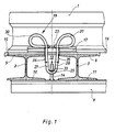
- Fig. 1 eine Schiene und Schienenbefestigung in Seitenansicht und
- Fig. 2 einen Querschnitt durch die Schiene nach Eig. 1 im Bereich des Zwischenraumes zwischen den H-Profilen der Y-förmigen Stahlschwelle.
- Fig. 1 is a rail and rail mounting in side view
- Fig. 2 shows a cross section through the rail according to Eig. 1 in the area of the space between the H-profiles of the Y-shaped steel sleeper.
Die Schienenbefestigung dient der Verbindung einer Schiene 1 mit Y-förmig ausgebildeten Stahlschwellen, die als Querschwellen das Gleis zum Gleisrost verbinden. Die Stahlschwellen sind aus zwei H-Profilen 2, 3 zusammengesetzt, die einen Abstand 4 aufweisen. Die Verbindung der H-Profile 2, 3 erfolgt durch zwei die Obergurte 5, 6 verbindende Rippen 7, 8 und ein weiteres Profilstück 9. Im Ausführungsbeispiel sind die Rippen 7, 8 und das Profilstück 9 mit den H-Profilen 2, 3 verschweißt. Das Profilstück 9 ist unterhalb der Untergurte 10, 11 angeordnet und weist als T-Profil einen Schenkel 12 auf, der nach unten ragt. Diese Ausbildung ist vorgesehen für den Einsatz der Schwellen auf Schotter. Der Schenkel 12 dient zur Erhöhung des Querverschiebewiderstandes. Im Zwischenraum 13 zwischen den H-Profilen 2, 3 ist ein Halteelement 14 angeordnet, das im Ausführungsbeispiel durch Schweißen mit dem Profilstück 9 verbunden ist. Bei der Ausbildung der Schienenbefestigung für eine feste Fahrbahn mit einer ebenen Auflage für die Schwellen kann jedoch vorgesehen werden, daß das Profilstück 9 und Halteelement 14 einstückig, beispielsweise als Schmiedeteil ausgebilet sind. Die Schienenbefestigung nach dem Ausführungsbeispiel ist als isolierte Schienenbefestigung ausgebildet. Dementsprechend ist zwischen Schiene 1 und Schwelle eine definierte elektrische Isolierung vorgesehen. Die Schiene 1 liegt auf einer Unterlagsplatte 15 mit der vorgesehenen Konizität zur Erzielung der Schienenneigung. Diese Unterlagsplatte 15 erstreckt sich über beide H-Profile 2, 3 der Schwelle. Zwischen Schienenfuß 16 und Rippen 7, 8 sind Abstandsstücke 17, 18 angeordnet, die zur Übertragung der Schienenseitenkräfte dienen. Bei unisolierter Ausbildung der Schienenbefestigung können diese Abstandsstücke 17, 18 entfallen. Dann werden die Schienenseitenkräfte direkt von der Schiene 1 über die Federklammern 19, 20 auf die Rippen 7, 8 übertragen.The rail fastening is used to connect a rail 1 with Y-shaped steel sleepers, which connect the track to the track grate as transverse sleepers. The steel sleepers are composed of two H-
Die Abstandsstücke 17, 18 übergreifen den Schienenfuß 16 mit einer Auflage 21, 22. Sie besitzen jeweils eine Aussparung 23, 24 zum Durchführen der Federklammern 19, 20. Die Federklammern 19, 20 sind ausgebildet mit Halteschlaufen 25, 26, die in Halteschlaufenstege 27, 28, 29 auslaufen und danach in Federschlaufen 30, 31, 32 übergehen. Die Halteschlaufenstege 27, 28, 29 laufen nach oben konisch auseinander. Die Halteschlaufen 25, 26 untergreifen Nasen 33, 34 des Profilstücks 9, das im Ausführungsbeispiel aus einem Blech hergestellt ist. Die Federschlaufen 30, 31, 32 der Federklammern 19, 20 halten über die Auflagen 21, 22 der Abstandsstücke 17, 18 den Schienenfuß 16 nieder. Im Ausführungsbeispiel ist der Abstand 4 der Obergurte 5, 6 der H-Profile 2, 3 geringer als das hier anliegende Außenmaß der Halteschlaufenstege 27, 28, 29 der Federklammern 19, 20 im unmontierten Zustand. Da die Halteschlaufenstege 27, 28, 29 sich nach oben erweitern, werden sie während der Montage beim Nachuntenschieben der Federklammern 19, 20 seitlich vorgespannt. Dadurch liegen sie an den Innenkanten 35, 36 der Obergurte 5, 6 der H-Profile 2, 3 an. Die beschriebene Schienenbefestigung kann seitenverstellbar ausgebildet sein. Für diese Ausbildung ist es vorgesehen, die Abstandsstücke 17, 18 mit unterschiedlicher Breite 37, 38 auszubilden. Die Schiene 1 liegt dann exzentrisch zwischen den Rippen 7, 8, wodurch eine Spur- oder Lageveränderung erzielt werden kann. Eine Höhenregulierung ist ebenfalls in einfacher Weise möglich. Hierbei werden unterschiedlich dicke Unterlagsplatten 15 eingesetzt. Die Abstandsdifferenz zwischen Schienenunterkante 39 und Nasenunterfläche des Halteelements 14 wird durch Aufschieben von nicht dargestellten Ausgleichsstücken auf die Nase 33, 34 oder die Halteschlaufe 24, 25 ausgeglichen.
- 1 Schiene
- 2 H-Profil
- 3 H-Profil
- 4 Abstand
- 5 Obergurt
- 6 Obergurt
- 7 Rippe
- 8 Rippe
- 9 Profilstück
- 10 Untergurt
- 11 Untergurt
- 12 Schenkel
- 13 Zwischenraum
- 14 Halteelement
- 15 Unterlagsplatte
- 16 Schienenfuß
- 17 Abstandsstück
- 18 Abstandsstück
- 19 Federklammer
- 20 Federklammer
- 21 Auflage
- 22 Auflage
- 23 Aussparung
- 24 Aussparung
- 25 Halteschlaufe
- 26 Halteschlaufe
- 27 Halteschlaufensteg
- 28 Halteschlaufensteg
- 29 Halteschlaufensteg
- 30 Federschlaufe
- 31 Federschlaufe
- 32 Federschlaufe
- 33 Nase
- 34 Nase
- 35 Innenkante
- 36 Innenkante
- 37 Breite
- 38 Breite
- 39 Schienenunterkante
- 1 rail
- 2 H profile
- 3 H profile
- 4 distance
- 5 top chord
- 6 top chord
- 7 rib
- 8 rib
- 9 profile piece
- 10 lower flange
- 11 lower flange
- 12 legs
- 13 space
- 14 holding element
- 15 base plate
- 16 rail base
- 17 spacer
- 18 spacer
- 19 spring clip
- 20 spring clip
- 21st edition
- 22 edition
- 23 recess
- 24 recess
- 25 hand strap
- 26 hand strap
- 27 strap strap
- 28 strap loop
- 29 strap strap
- 30 spring loop
- 31 spring loop
- 32 spring loop
- 33 nose
- 34 nose
- 35 inner edge
- 36 inner edge
- 37 width
- 38 width
- 39 lower edge of rail
Claims (6)
- das Profilstück (9) unterhalb der Schienenauflage ein im Zwischenraum (13) angeordnetes Halteelement (14) trägt,
- eine oder zwei Federklammern (19, 20) mit jeweils zwei den Schienenfuß (16) niederhaltenden Federschlaufen (30, 31, 32) und jeweils einer diese verbindenden, in den Zwischenraum (13) ragende Halteschlaufe (25, 26) das Halteelement (14) untergreift und
- die Federklammer (19, 20) jeweils zwischen Schienenfußaußenkante und Rippe (7, 8) angeordnet ist.1. Resilient rail fastening for Y-shaped steel sleepers, which are composed of an intermediate H-profiles and have welded ribs on the top flange in the area next to the rail support and a further profile piece arranged between the H-profiles, characterized in that
- The profile piece (9) below the rail support carries a holding element (14) arranged in the intermediate space (13),
- One or two spring clips (19, 20), each with two spring loops (30, 31, 32) holding down the rail foot (16) and one each connecting loop, which projects into the intermediate space (13) and holds the holding element (14 ) engages and
- The spring clip (19, 20) is arranged between the outer edge of the rail foot and the rib (7, 8).
Priority Applications (1)
| Application Number | Priority Date | Filing Date | Title |
|---|---|---|---|
| AT89114532T ATE76137T1 (en) | 1988-09-30 | 1989-08-07 | RESILIENT RAIL MOUNTING. |
Applications Claiming Priority (2)
| Application Number | Priority Date | Filing Date | Title |
|---|---|---|---|
| DE3833265A DE3833265C1 (en) | 1988-09-30 | 1988-09-30 | |
| DE3833265 | 1988-09-30 |
Publications (2)
| Publication Number | Publication Date |
|---|---|
| EP0363591A1 true EP0363591A1 (en) | 1990-04-18 |
| EP0363591B1 EP0363591B1 (en) | 1992-05-13 |
Family
ID=6364091
Family Applications (1)
| Application Number | Title | Priority Date | Filing Date |
|---|---|---|---|
| EP89114532A Expired - Lifetime EP0363591B1 (en) | 1988-09-30 | 1989-08-07 | Elastic rail fastening |
Country Status (8)
| Country | Link |
|---|---|
| EP (1) | EP0363591B1 (en) |
| AT (1) | ATE76137T1 (en) |
| DD (1) | DD285621A5 (en) |
| DE (2) | DE3833265C1 (en) |
| DK (1) | DK166508B1 (en) |
| ES (1) | ES2019576T3 (en) |
| GR (1) | GR3005430T3 (en) |
| NO (1) | NO168062C (en) |
Families Citing this family (1)
| Publication number | Priority date | Publication date | Assignee | Title |
|---|---|---|---|---|
| DE4109068C2 (en) * | 1991-03-20 | 1995-01-19 | Langen & Sondermann Gmbh & Co | Device for fastening rails to sleepers or the like |
Citations (6)
| Publication number | Priority date | Publication date | Assignee | Title |
|---|---|---|---|---|
| GB715866A (en) * | 1952-07-30 | 1954-09-22 | United Steel Companies Ltd | Improvements in or relating to the securing of railway rails |
| DE2602869B1 (en) * | 1976-01-27 | 1977-04-21 | Hoesch Werke Ag | SPRING RAIL FASTENING |
| DE3408597A1 (en) * | 1984-03-09 | 1985-09-12 | Hoesch Ag, 4600 Dortmund | CONCRETE THRESHOLD WITH RECESSES AND METHOD FOR THEIR PRODUCTION |
| DE3521673A1 (en) * | 1984-11-08 | 1986-05-22 | Stahlwerke Peine-Salzgitter Ag, 3320 Salzgitter | Device for fastening rails of a railway on steel sleepers, in particular on Y-type steel sleepers |
| EP0192268A2 (en) * | 1985-02-22 | 1986-08-27 | Preussag Stahl Aktiengesellschaft | Device for fastening railway rails on steel sleepers |
| DE8709429U1 (en) * | 1987-07-09 | 1987-08-27 | Stahlwerke Peine-Salzgitter Ag, 3150 Peine | Positioning security for steel sleepers |
-
1988
- 1988-09-30 DE DE3833265A patent/DE3833265C1/de not_active Expired
-
1989
- 1989-08-07 DE DE8989114532T patent/DE58901411D1/en not_active Expired - Lifetime
- 1989-08-07 ES ES198989114532T patent/ES2019576T3/en not_active Expired - Lifetime
- 1989-08-07 AT AT89114532T patent/ATE76137T1/en not_active IP Right Cessation
- 1989-08-07 EP EP89114532A patent/EP0363591B1/en not_active Expired - Lifetime
- 1989-09-25 DD DD89332938A patent/DD285621A5/en not_active IP Right Cessation
- 1989-09-28 DK DK477989A patent/DK166508B1/en not_active IP Right Cessation
- 1989-09-28 NO NO893866A patent/NO168062C/en unknown
-
1992
- 1992-08-13 GR GR920401749T patent/GR3005430T3/el unknown
Patent Citations (6)
| Publication number | Priority date | Publication date | Assignee | Title |
|---|---|---|---|---|
| GB715866A (en) * | 1952-07-30 | 1954-09-22 | United Steel Companies Ltd | Improvements in or relating to the securing of railway rails |
| DE2602869B1 (en) * | 1976-01-27 | 1977-04-21 | Hoesch Werke Ag | SPRING RAIL FASTENING |
| DE3408597A1 (en) * | 1984-03-09 | 1985-09-12 | Hoesch Ag, 4600 Dortmund | CONCRETE THRESHOLD WITH RECESSES AND METHOD FOR THEIR PRODUCTION |
| DE3521673A1 (en) * | 1984-11-08 | 1986-05-22 | Stahlwerke Peine-Salzgitter Ag, 3320 Salzgitter | Device for fastening rails of a railway on steel sleepers, in particular on Y-type steel sleepers |
| EP0192268A2 (en) * | 1985-02-22 | 1986-08-27 | Preussag Stahl Aktiengesellschaft | Device for fastening railway rails on steel sleepers |
| DE8709429U1 (en) * | 1987-07-09 | 1987-08-27 | Stahlwerke Peine-Salzgitter Ag, 3150 Peine | Positioning security for steel sleepers |
Also Published As
| Publication number | Publication date |
|---|---|
| ES2019576A4 (en) | 1991-07-01 |
| NO893866L (en) | 1990-04-02 |
| DK477989D0 (en) | 1989-09-28 |
| NO893866D0 (en) | 1989-09-28 |
| DK166508B1 (en) | 1993-06-01 |
| ATE76137T1 (en) | 1992-05-15 |
| DK477989A (en) | 1990-03-31 |
| DD285621A5 (en) | 1990-12-19 |
| NO168062C (en) | 1992-01-08 |
| EP0363591B1 (en) | 1992-05-13 |
| ES2019576T3 (en) | 1993-03-01 |
| DE58901411D1 (en) | 1992-06-17 |
| NO168062B (en) | 1991-09-30 |
| GR3005430T3 (en) | 1993-05-24 |
| DE3833265C1 (en) | 1989-10-19 |
Similar Documents
| Publication | Publication Date | Title |
|---|---|---|
| EP2318589B1 (en) | Device for mounting railroad tracks on a substructure | |
| EP2229479B1 (en) | Support for a rail fastening system and rail fastening system | |
| EP2478154A1 (en) | System for securing a rail and securing a rail | |
| EP0794290B1 (en) | Laterally adjustable elastic rail fastening | |
| DE2715717A1 (en) | ANCHOR RAIL WITH RAIL BRACKET FOR A MAGNETIC LIFT VEHICLE | |
| EP1488041B1 (en) | Method for precisely placing a guideway support, and guideway | |
| EP0377765B1 (en) | Concrete sleeper adaptable to two track gauges | |
| DE60022883T2 (en) | SUSPENDED RAIL FIXING UNIT | |
| EP1070789B1 (en) | Anchorage for a post | |
| EP0432357A1 (en) | Device for applying rails for rail vehicles | |
| EP1914347B1 (en) | level crossing device | |
| EP0363591B1 (en) | Elastic rail fastening | |
| EP0794289A1 (en) | Elastic rail fastening | |
| EP2598695B1 (en) | Carrying panel with elastic rail attachment | |
| DE2602869C2 (en) | Spring-loaded rail fastening | |
| EP0545123B1 (en) | Rail fastening arrangement | |
| EP0455236B1 (en) | Rail fastener | |
| EP1528151B1 (en) | Rail fastening assembly | |
| DE8915837U1 (en) | Facility for storing rails for rail vehicles | |
| DE4214605A1 (en) | Expansion joint on underlay for rail section - includes sliding tongue held against stock rail by clips | |
| EP0759106B1 (en) | Rail fastening | |
| DE7908757U1 (en) | ROAD PLATE | |
| EP0374442B1 (en) | Concrete sleeper with a rail fastener | |
| EP3850155B1 (en) | Guide plate and rail fastening point | |
| EP0648290B1 (en) | Rail anchoring device with plastic spring element |
Legal Events
| Date | Code | Title | Description |
|---|---|---|---|
| PUAI | Public reference made under article 153(3) epc to a published international application that has entered the european phase |
Free format text: ORIGINAL CODE: 0009012 |
|
| AK | Designated contracting states |
Kind code of ref document: A1 Designated state(s): AT BE CH DE ES FR GB GR IT LI LU NL SE |
|
| 17P | Request for examination filed |
Effective date: 19900512 |
|
| TCNL | Nl: translation of patent claims filed | ||
| GBC | Gb: translation of claims filed (gb section 78(7)/1977) | ||
| EL | Fr: translation of claims filed | ||
| ITCL | It: translation for ep claims filed |
Representative=s name: RICCARDI SERGIO & CO. |
|
| 17Q | First examination report despatched |
Effective date: 19910415 |
|
| GRAA | (expected) grant |
Free format text: ORIGINAL CODE: 0009210 |
|
| AK | Designated contracting states |
Kind code of ref document: B1 Designated state(s): AT BE CH DE ES FR GB GR IT LI LU NL SE |
|
| REF | Corresponds to: |
Ref document number: 76137 Country of ref document: AT Date of ref document: 19920515 Kind code of ref document: T |
|
| REF | Corresponds to: |
Ref document number: 58901411 Country of ref document: DE Date of ref document: 19920617 |
|
| RAP2 | Party data changed (patent owner data changed or rights of a patent transferred) |
Owner name: PREUSSAG STAHL AKTIENGESELLSCHAFT Owner name: HOESCH AKTIENGESELLSCHAFT |
|
| REG | Reference to a national code |
Ref country code: CH Ref legal event code: PUE Owner name: HOESCH AKTIENGESELLSCHAFT |
|
| ITF | It: translation for a ep patent filed | ||
| ET | Fr: translation filed | ||
| GBT | Gb: translation of ep patent filed (gb section 77(6)(a)/1977) | ||
| NLT2 | Nl: modifications (of names), taken from the european patent patent bulletin |
Owner name: HOESCH AKTIENGESELLSCHAFT TE DORTMUND EN PREUSSAG |
|
| REG | Reference to a national code |
Ref country code: GR Ref legal event code: FG4A Free format text: 3005430 |
|
| REG | Reference to a national code |
Ref country code: ES Ref legal event code: FG2A Ref document number: 2019576 Country of ref document: ES Kind code of ref document: T3 |
|
| RAP2 | Party data changed (patent owner data changed or rights of a patent transferred) |
Owner name: PREUSSAG STAHL AKTIENGESELLSCHAFT Owner name: FRIED. KRUPP AG HOESCH-KRUPP |
|
| PLBE | No opposition filed within time limit |
Free format text: ORIGINAL CODE: 0009261 |
|
| STAA | Information on the status of an ep patent application or granted ep patent |
Free format text: STATUS: NO OPPOSITION FILED WITHIN TIME LIMIT |
|
| NLXE | Nl: other communications concerning ep-patents (part 3 heading xe) |
Free format text: IN PAT.BUL.20/92 PAGES 3139 AND 3180 CORR.:HOESCH AKTIENGESELLSCHAFT AND STAHLWERKE PEINE-SALZGITTER AKTIENGESELLSCHAFT PAT.BUL.23/92 PAGE 3677 SHOULD BE DELETED |
|
| 26N | No opposition filed | ||
| NLT2 | Nl: modifications (of names), taken from the european patent patent bulletin |
Owner name: FRIEDR. KRUPP AG HOESCH-KRUPP TE DORTMUND EN PREUS |
|
| PGFP | Annual fee paid to national office [announced via postgrant information from national office to epo] |
Ref country code: FR Payment date: 19930723 Year of fee payment: 5 |
|
| PGFP | Annual fee paid to national office [announced via postgrant information from national office to epo] |
Ref country code: SE Payment date: 19930726 Year of fee payment: 5 Ref country code: GB Payment date: 19930726 Year of fee payment: 5 Ref country code: DE Payment date: 19930726 Year of fee payment: 5 Ref country code: CH Payment date: 19930726 Year of fee payment: 5 |
|
| PGFP | Annual fee paid to national office [announced via postgrant information from national office to epo] |
Ref country code: BE Payment date: 19930727 Year of fee payment: 5 |
|
| PGFP | Annual fee paid to national office [announced via postgrant information from national office to epo] |
Ref country code: AT Payment date: 19930729 Year of fee payment: 5 |
|
| PGFP | Annual fee paid to national office [announced via postgrant information from national office to epo] |
Ref country code: LU Payment date: 19930730 Year of fee payment: 5 |
|
| PGFP | Annual fee paid to national office [announced via postgrant information from national office to epo] |
Ref country code: GR Payment date: 19930802 Year of fee payment: 5 |
|
| PGFP | Annual fee paid to national office [announced via postgrant information from national office to epo] |
Ref country code: ES Payment date: 19930826 Year of fee payment: 5 |
|
| PGFP | Annual fee paid to national office [announced via postgrant information from national office to epo] |
Ref country code: NL Payment date: 19930831 Year of fee payment: 5 |
|
| EPTA | Lu: last paid annual fee | ||
| PG25 | Lapsed in a contracting state [announced via postgrant information from national office to epo] |
Ref country code: LU Free format text: LAPSE BECAUSE OF NON-PAYMENT OF DUE FEES Effective date: 19940807 Ref country code: GB Effective date: 19940807 Ref country code: AT Effective date: 19940807 |
|
| PG25 | Lapsed in a contracting state [announced via postgrant information from national office to epo] |
Ref country code: SE Effective date: 19940808 Ref country code: ES Free format text: LAPSE BECAUSE OF NON-PAYMENT OF DUE FEES Effective date: 19940808 |
|
| PG25 | Lapsed in a contracting state [announced via postgrant information from national office to epo] |
Ref country code: LI Effective date: 19940831 Ref country code: CH Effective date: 19940831 Ref country code: BE Effective date: 19940831 |
|
| EAL | Se: european patent in force in sweden |
Ref document number: 89114532.8 |
|
| BERE | Be: lapsed |
Owner name: PREUSSAG STAHL A.G. Effective date: 19940831 Owner name: HOESCH A.G. Effective date: 19940831 |
|
| PG25 | Lapsed in a contracting state [announced via postgrant information from national office to epo] |
Ref country code: GR Free format text: THE PATENT HAS BEEN ANNULLED BY A DECISION OF A NATIONAL AUTHORITY Effective date: 19950228 |
|
| PG25 | Lapsed in a contracting state [announced via postgrant information from national office to epo] |
Ref country code: NL Free format text: LAPSE BECAUSE OF NON-PAYMENT OF DUE FEES Effective date: 19950301 |
|
| GBPC | Gb: european patent ceased through non-payment of renewal fee |
Effective date: 19940807 |
|
| NLV4 | Nl: lapsed or anulled due to non-payment of the annual fee | ||
| PG25 | Lapsed in a contracting state [announced via postgrant information from national office to epo] |
Ref country code: FR Effective date: 19950428 |
|
| REG | Reference to a national code |
Ref country code: CH Ref legal event code: PL Ref country code: GR Ref legal event code: MM2A Free format text: 3005430 |
|
| PG25 | Lapsed in a contracting state [announced via postgrant information from national office to epo] |
Ref country code: DE Effective date: 19950503 |
|
| EUG | Se: european patent has lapsed |
Ref document number: 89114532.8 |
|
| REG | Reference to a national code |
Ref country code: FR Ref legal event code: ST |
|
| REG | Reference to a national code |
Ref country code: ES Ref legal event code: FD2A Effective date: 19990503 |
|
| PG25 | Lapsed in a contracting state [announced via postgrant information from national office to epo] |
Ref country code: IT Free format text: LAPSE BECAUSE OF NON-PAYMENT OF DUE FEES;WARNING: LAPSES OF ITALIAN PATENTS WITH EFFECTIVE DATE BEFORE 2007 MAY HAVE OCCURRED AT ANY TIME BEFORE 2007. THE CORRECT EFFECTIVE DATE MAY BE DIFFERENT FROM THE ONE RECORDED. Effective date: 20050807 |