EP0363313B1 - Foret à couronne à pierre - Google Patents
Foret à couronne à pierre Download PDFInfo
- Publication number
- EP0363313B1 EP0363313B1 EP89810691A EP89810691A EP0363313B1 EP 0363313 B1 EP0363313 B1 EP 0363313B1 EP 89810691 A EP89810691 A EP 89810691A EP 89810691 A EP89810691 A EP 89810691A EP 0363313 B1 EP0363313 B1 EP 0363313B1
- Authority
- EP
- European Patent Office
- Prior art keywords
- predetermined breaking
- breaking points
- slots
- drilling tool
- drill bit
- Prior art date
- Legal status (The legal status is an assumption and is not a legal conclusion. Google has not performed a legal analysis and makes no representation as to the accuracy of the status listed.)
- Expired - Lifetime
Links
- 238000005553 drilling Methods 0.000 title abstract description 23
- 238000005520 cutting process Methods 0.000 claims abstract description 18
- 230000009467 reduction Effects 0.000 claims abstract 2
- 239000000463 material Substances 0.000 claims description 5
- 230000003313 weakening effect Effects 0.000 claims description 3
- 239000011435 rock Substances 0.000 claims description 2
- 239000000498 cooling water Substances 0.000 abstract description 11
- XLYOFNOQVPJJNP-UHFFFAOYSA-N water Substances O XLYOFNOQVPJJNP-UHFFFAOYSA-N 0.000 description 8
- XEEYBQQBJWHFJM-UHFFFAOYSA-N Iron Chemical compound [Fe] XEEYBQQBJWHFJM-UHFFFAOYSA-N 0.000 description 2
- 238000004049 embossing Methods 0.000 description 2
- 238000004080 punching Methods 0.000 description 2
- 208000031872 Body Remains Diseases 0.000 description 1
- 235000019219 chocolate Nutrition 0.000 description 1
- 239000010432 diamond Substances 0.000 description 1
- 229910052742 iron Inorganic materials 0.000 description 1
- 238000003754 machining Methods 0.000 description 1
- 238000004519 manufacturing process Methods 0.000 description 1
- 230000002787 reinforcement Effects 0.000 description 1
Images
Classifications
-
- E—FIXED CONSTRUCTIONS
- E21—EARTH OR ROCK DRILLING; MINING
- E21B—EARTH OR ROCK DRILLING; OBTAINING OIL, GAS, WATER, SOLUBLE OR MELTABLE MATERIALS OR A SLURRY OF MINERALS FROM WELLS
- E21B10/00—Drill bits
- E21B10/62—Drill bits characterised by parts, e.g. cutting elements, which are detachable or adjustable
-
- B—PERFORMING OPERATIONS; TRANSPORTING
- B28—WORKING CEMENT, CLAY, OR STONE
- B28D—WORKING STONE OR STONE-LIKE MATERIALS
- B28D1/00—Working stone or stone-like materials, e.g. brick, concrete or glass, not provided for elsewhere; Machines, devices, tools therefor
- B28D1/02—Working stone or stone-like materials, e.g. brick, concrete or glass, not provided for elsewhere; Machines, devices, tools therefor by sawing
- B28D1/04—Working stone or stone-like materials, e.g. brick, concrete or glass, not provided for elsewhere; Machines, devices, tools therefor by sawing with circular or cylindrical saw-blades or saw-discs
- B28D1/041—Working stone or stone-like materials, e.g. brick, concrete or glass, not provided for elsewhere; Machines, devices, tools therefor by sawing with circular or cylindrical saw-blades or saw-discs with cylinder saws, e.g. trepanning; saw cylinders, e.g. having their cutting rim equipped with abrasive particles
-
- E—FIXED CONSTRUCTIONS
- E21—EARTH OR ROCK DRILLING; MINING
- E21B—EARTH OR ROCK DRILLING; OBTAINING OIL, GAS, WATER, SOLUBLE OR MELTABLE MATERIALS OR A SLURRY OF MINERALS FROM WELLS
- E21B10/00—Drill bits
- E21B10/46—Drill bits characterised by wear resisting parts, e.g. diamond inserts
- E21B10/48—Drill bits characterised by wear resisting parts, e.g. diamond inserts the bit being of core type
-
- E—FIXED CONSTRUCTIONS
- E21—EARTH OR ROCK DRILLING; MINING
- E21B—EARTH OR ROCK DRILLING; OBTAINING OIL, GAS, WATER, SOLUBLE OR MELTABLE MATERIALS OR A SLURRY OF MINERALS FROM WELLS
- E21B10/00—Drill bits
- E21B10/60—Drill bits characterised by conduits or nozzles for drilling fluids
- E21B10/605—Drill bits characterised by conduits or nozzles for drilling fluids the bit being a core-bit
Definitions
- the invention relates to a hollow drilling tool, in particular for rock such as concrete and the like, with a tubular support body which is provided at its front end in the feed direction with cutting segments containing hard materials and at least partially embedded in the support body.
- Hollow drilling tools of the type mentioned are used, in particular, for creating openings of larger diameter in buildings and increasingly also for dowel holes in concrete having iron reinforcements.
- the cutting segments usually contain synthetically produced diamonds as hard materials.
- the carrier body has, between the cutting segments, axially and radially extending slots extending from the front end and serving for the passage of the cooling water supplied through the hollow drilling tool.
- the cooling water is supplied under more or less high pressure, the slits being able to be smaller the higher the prevailing pressure.
- the slots may be dispensed with entirely, since the cooling water on the face of the hollow drilling tool passes from the inside to the outside. Conversely, large cross sections of the slots are necessary when the cooling water pressure is low. If the cross section of the slots is large and the pressure of the cooling water is high, the cooling water only flows through the slots from the inside to the outside of the hollow drilling tool and the face of the hollow drilling tool which is subjected to the greatest stress is practically not cooled.
- the invention has for its object to provide a hollow drilling tool that allows the user to easily make and adapt slots to the given conditions.
- the carrier body has one or more predetermined breaking points, which are arranged between individual cutting segments and run essentially in a U-shape and are open towards the front end and are formed by cross-sectional weakenings.
- the user is able to easily break out the slits along the predetermined breaking points if necessary.
- This breaking out can be done, for example, using pliers.
- the predetermined breaking points are expediently formed by recesses from one side.
- the recesses are preferably made before the cutting segments are inserted.
- the recesses can be formed over a large area in accordance with the desired cross section of the water slots or as notches surrounding the slots. In the former case a kind of floating skin is created, in the second case the material thickness of the support body remains the same in the area of the slot to be made as in the other areas of the support body.
- the recesses are preferably made from the outside of the carrier body, since this is more accessible than the inside.
- the recesses can be made by embossing or machining.
- Another advantageous embodiment consists in forming the predetermined breaking points by means of two recesses arranged radially opposite one another.
- the provision of recesses arranged opposite one another is particularly in the case of non-cutting production by embossing the recesses advantageous since the forces acting radially on the tubular support body cancel each other out and there is no deformation of the support body.
- the recesses can be formed over a large area or as notches surrounding the slots.
- Another expedient embodiment consists in forming the predetermined breaking points through perforations.
- Such perforations can be made, for example, by drilling or punching small holes in the tubular support body. For certain applications, the sum of the cross-section of these holes can then suffice for the cooling water to pass through.
- the web connecting the legs of the U-shaped predetermined breaking points is advantageously arranged at a different distance from the front end of the carrier body.
- slots of different lengths and cross sections can be broken out. This enables the slots to be optimally adapted to the given pressure conditions of the cooling water.
- the effective cross section of the slots can be kept approximately constant over the entire period of use of the hollow drilling tool by successively breaking out slots of different depths.
- the cross section of the slots can also be changed by different widths, ie by the distance between the two webs.
- the cross section of the slots In order to adapt the cross section of the slots, it is also expedient that several webs connecting the legs are provided. The entire depth of the slots is divided so that a gradual breaking out according to the desired cross section is made possible. In addition, by gradually breaking out individual parts, the cross-section can be kept approximately constant despite wear of the cutting segments.
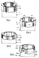
- the hollow drilling tool shown in FIGS. 1 and 2 essentially consists of a tubular carrier body 1 and at the front end of which cutting segments 2 are completely embedded in receptacles 1a Provide recesses 1c.
- the recesses 1b and 1c are arranged radially opposite one another and have the shape of V-shaped notches.
- the recesses 1b and 1c form predetermined breaking points which act as cross-sectional weakenings and which allow water slots 1d to be broken out.
- the water slots 1d shown in FIG. 2 can be broken out in stages in accordance with the breaking off of a chocolate bar. This enables the cross section of the slots 1d to be adapted to the given conditions. With increasing wear of the cutting segments 2, further parts can also be broken out, so that the cross section of the slots 1d remains approximately the same during the entire period of use of the hollow drilling tool.
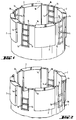
- the hollow drilling tool shown in FIG. 3 consists of a tubular support body 11 and completely in receptacles 11a at the front end of the cutting body 12.
- the recesses 11b create a type of webbed skin with a reduced wall thickness compared to the rest of the carrier body.
- the recesses 11b also allow slots to be easily broken out, which can be done, for example, using pliers.
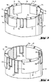
- the hollow drilling tool shown in FIG. 4 consists of a tubular carrier body 21 and at the front end of which there are cutting segments 22 embedded in receptacles 21a.
- the carrier body 21 is provided with continuous perforations 21b and 21c between the cutting segments. These perforations 21b and 21c enable water slots of different sizes to be broken out. The user can thus either break out only one of the two water slots or both water slots. Furthermore, it is possible to first break out the water slot 21d of less depth and, after the cutting segments 22 have worn out correspondingly, the part of the water slot 21e remaining in the carrier body.
- the perforations 21b and 21c can be created by punching or drilling holes.
Landscapes
- Engineering & Computer Science (AREA)
- Mining & Mineral Resources (AREA)
- Life Sciences & Earth Sciences (AREA)
- Geology (AREA)
- Mechanical Engineering (AREA)
- Physics & Mathematics (AREA)
- Environmental & Geological Engineering (AREA)
- Fluid Mechanics (AREA)
- General Life Sciences & Earth Sciences (AREA)
- Geochemistry & Mineralogy (AREA)
- Processing Of Stones Or Stones Resemblance Materials (AREA)
- Earth Drilling (AREA)
Claims (6)
Priority Applications (1)
| Application Number | Priority Date | Filing Date | Title |
|---|---|---|---|
| AT89810691T ATE79071T1 (de) | 1988-10-05 | 1989-09-14 | Hohlbohrwerkzeug fuer gestein. |
Applications Claiming Priority (2)
| Application Number | Priority Date | Filing Date | Title |
|---|---|---|---|
| DE3833767 | 1988-10-05 | ||
| DE3833767A DE3833767A1 (de) | 1988-10-05 | 1988-10-05 | Hohlbohrwerkzeug fuer gestein |
Publications (3)
| Publication Number | Publication Date |
|---|---|
| EP0363313A2 EP0363313A2 (fr) | 1990-04-11 |
| EP0363313A3 EP0363313A3 (en) | 1990-12-27 |
| EP0363313B1 true EP0363313B1 (fr) | 1992-08-05 |
Family
ID=6364376
Family Applications (1)
| Application Number | Title | Priority Date | Filing Date |
|---|---|---|---|
| EP89810691A Expired - Lifetime EP0363313B1 (fr) | 1988-10-05 | 1989-09-14 | Foret à couronne à pierre |
Country Status (3)
| Country | Link |
|---|---|
| EP (1) | EP0363313B1 (fr) |
| AT (1) | ATE79071T1 (fr) |
| DE (2) | DE3833767A1 (fr) |
Cited By (2)
| Publication number | Priority date | Publication date | Assignee | Title |
|---|---|---|---|---|
| US8485283B2 (en) | 2007-09-05 | 2013-07-16 | Groupe Fordia Inc. | Drill bit |
| CN109930999A (zh) * | 2019-04-01 | 2019-06-25 | 无锡锡钻地质装备有限公司 | 一种地质勘探钻头及其制造工艺 |
Families Citing this family (9)
| Publication number | Priority date | Publication date | Assignee | Title |
|---|---|---|---|---|
| FR2666843B1 (fr) * | 1990-09-14 | 1992-12-24 | Total Petroles | Taillant d'outil de forage auto-affutable. |
| DE4301985C2 (de) * | 1993-01-26 | 1997-06-05 | Bilfinger Berger Bau | Verfahren zum Herstellen eines Bohrlochs für die Injektion von mit Zement gebundenen Füllgütern in Rissen |
| WO2006076795A1 (fr) | 2005-01-18 | 2006-07-27 | Groupe Fordia Inc | Meche pour percer un trou |
| CN103774996A (zh) * | 2014-01-26 | 2014-05-07 | 中国地质大学(武汉) | 不产生空穴现象的金刚石钻头 |
| RU2577351C1 (ru) * | 2015-01-26 | 2016-03-20 | Александр Александрович Третьяк | Стабилизирующая кольцевая буровая коронка |
| RU2613712C1 (ru) * | 2016-03-29 | 2017-03-21 | Александр Александрович Третьяк | Антивибрационная кольцевая буровая коронка |
| RU171734U1 (ru) * | 2017-01-09 | 2017-06-13 | Федеральное государственное автономное образовательное учреждение высшего образования "Сибирский федеральный университет" | Алмазная коронка для бурения |
| RU202233U1 (ru) * | 2020-02-28 | 2021-02-08 | Федеральное государственное автономное образовательное учреждение высшего образования "Сибирский федеральный университет" | Алмазная коронка для бурения |
| RU2745546C1 (ru) * | 2020-10-12 | 2021-03-26 | Федеральное государственное автономное образовательное учреждение высшего образования "Сибирский федеральный университет" | Алмазная буровая коронка |
Family Cites Families (3)
| Publication number | Priority date | Publication date | Assignee | Title |
|---|---|---|---|---|
| JPS5382601A (en) * | 1976-12-28 | 1978-07-21 | Tokiwa Kogyo Kk | Rotary grinding type excavation drill head |
| US4128136A (en) * | 1977-12-09 | 1978-12-05 | Lamage Limited | Drill bit |
| DE3706641A1 (de) * | 1987-03-02 | 1988-09-15 | Hilti Ag | Hohlbohrer |
-
1988
- 1988-10-05 DE DE3833767A patent/DE3833767A1/de not_active Withdrawn
-
1989
- 1989-09-14 AT AT89810691T patent/ATE79071T1/de not_active IP Right Cessation
- 1989-09-14 DE DE8989810691T patent/DE58901984D1/de not_active Expired - Fee Related
- 1989-09-14 EP EP89810691A patent/EP0363313B1/fr not_active Expired - Lifetime
Cited By (2)
| Publication number | Priority date | Publication date | Assignee | Title |
|---|---|---|---|---|
| US8485283B2 (en) | 2007-09-05 | 2013-07-16 | Groupe Fordia Inc. | Drill bit |
| CN109930999A (zh) * | 2019-04-01 | 2019-06-25 | 无锡锡钻地质装备有限公司 | 一种地质勘探钻头及其制造工艺 |
Also Published As
| Publication number | Publication date |
|---|---|
| EP0363313A2 (fr) | 1990-04-11 |
| ATE79071T1 (de) | 1992-08-15 |
| EP0363313A3 (en) | 1990-12-27 |
| DE58901984D1 (de) | 1992-09-10 |
| DE3833767A1 (de) | 1990-04-12 |
Similar Documents
| Publication | Publication Date | Title |
|---|---|---|
| DE3035867C2 (fr) | ||
| DE69301369T2 (de) | Betonanker | |
| EP0470354B1 (fr) | Foret à fabriquer des trous cylindriques | |
| DE2831012C2 (de) | Nietkörper für einen Heftniet | |
| DE2846699A1 (de) | Bohrloch-beruehrungsvorrichtung fuer grundloch-anordnungen | |
| EP0363313B1 (fr) | Foret à couronne à pierre | |
| DE3507817A1 (de) | Bohrer zur erzeugung einer hinterschneidung in einer bohrung | |
| EP0697529A1 (fr) | Cheville d'expansion en matière plastique | |
| EP2048383B1 (fr) | Vis autoforeuse | |
| DE2846759A1 (de) | Honwerkzeug und dieses honwerkzeug enthaltende honmaschine | |
| DE4405085A1 (de) | Spreizbares Honwerkzeug in Modularbauweise | |
| DE10142265A1 (de) | Stabförmiges Werkzeug zur spanenden Bearbeitung eines Werkstücks | |
| EP0660003B1 (fr) | Méthode de fabrication d'un manchon expansible pour un cheville expansible | |
| WO2002103212A1 (fr) | Tige d'ancrage | |
| DE2331467B2 (de) | Vorrichtung zum Ausbohren einer Bohrung mit einem zylindrischen und einem konischen Bereich | |
| DE6802178U (de) | Huelsenanker. | |
| DE3225807C2 (de) | Werkzeug zur Herstellung von Bohrlöchern in grobporigen, zusammendrückbaren Böden | |
| DE3510163C2 (fr) | ||
| EP0188173B1 (fr) | Cheville à expansion avec élément expansif en forme de coin | |
| EP0995913B1 (fr) | Cheville pour trou de forage à contre-dépouille | |
| DE2922567C2 (fr) | ||
| DE3334754C2 (fr) | ||
| EP0007980A1 (fr) | Organe de fixation à tige s'évasant, outil et procédé de préparation des trous pour de tels organes de fixation | |
| EP0701068B1 (fr) | Cheville d'ancre d'isolation | |
| EP0087648A1 (fr) | Cheville d'écartement tubulaire |
Legal Events
| Date | Code | Title | Description |
|---|---|---|---|
| PUAI | Public reference made under article 153(3) epc to a published international application that has entered the european phase |
Free format text: ORIGINAL CODE: 0009012 |
|
| AK | Designated contracting states |
Kind code of ref document: A2 Designated state(s): AT BE CH DE LI SE |
|
| PUAL | Search report despatched |
Free format text: ORIGINAL CODE: 0009013 |
|
| AK | Designated contracting states |
Kind code of ref document: A3 Designated state(s): AT BE CH DE LI SE |
|
| 17P | Request for examination filed |
Effective date: 19910114 |
|
| 17Q | First examination report despatched |
Effective date: 19920120 |
|
| GRAA | (expected) grant |
Free format text: ORIGINAL CODE: 0009210 |
|
| AK | Designated contracting states |
Kind code of ref document: B1 Designated state(s): AT BE CH DE LI SE |
|
| REF | Corresponds to: |
Ref document number: 79071 Country of ref document: AT Date of ref document: 19920815 Kind code of ref document: T |
|
| REF | Corresponds to: |
Ref document number: 58901984 Country of ref document: DE Date of ref document: 19920910 |
|
| PGFP | Annual fee paid to national office [announced via postgrant information from national office to epo] |
Ref country code: BE Payment date: 19921013 Year of fee payment: 4 |
|
| PLBE | No opposition filed within time limit |
Free format text: ORIGINAL CODE: 0009261 |
|
| STAA | Information on the status of an ep patent application or granted ep patent |
Free format text: STATUS: NO OPPOSITION FILED WITHIN TIME LIMIT |
|
| 26N | No opposition filed | ||
| PG25 | Lapsed in a contracting state [announced via postgrant information from national office to epo] |
Ref country code: BE Effective date: 19930930 |
|
| BERE | Be: lapsed |
Owner name: HILTI A.G. Effective date: 19930930 |
|
| EAL | Se: european patent in force in sweden |
Ref document number: 89810691.9 |
|
| PGFP | Annual fee paid to national office [announced via postgrant information from national office to epo] |
Ref country code: AT Payment date: 19970710 Year of fee payment: 9 |
|
| PG25 | Lapsed in a contracting state [announced via postgrant information from national office to epo] |
Ref country code: AT Free format text: LAPSE BECAUSE OF NON-PAYMENT OF DUE FEES Effective date: 19980914 |
|
| PGFP | Annual fee paid to national office [announced via postgrant information from national office to epo] |
Ref country code: SE Payment date: 20000906 Year of fee payment: 12 |
|
| PG25 | Lapsed in a contracting state [announced via postgrant information from national office to epo] |
Ref country code: SE Free format text: LAPSE BECAUSE OF NON-PAYMENT OF DUE FEES Effective date: 20010915 |
|
| EUG | Se: european patent has lapsed |
Ref document number: 89810691.9 |
|
| PGFP | Annual fee paid to national office [announced via postgrant information from national office to epo] |
Ref country code: DE Payment date: 20050818 Year of fee payment: 17 |
|
| PG25 | Lapsed in a contracting state [announced via postgrant information from national office to epo] |
Ref country code: DE Free format text: LAPSE BECAUSE OF NON-PAYMENT OF DUE FEES Effective date: 20070403 |
|
| PGFP | Annual fee paid to national office [announced via postgrant information from national office to epo] |
Ref country code: CH Payment date: 20070913 Year of fee payment: 19 |
|
| REG | Reference to a national code |
Ref country code: CH Ref legal event code: PL |
|
| PG25 | Lapsed in a contracting state [announced via postgrant information from national office to epo] |
Ref country code: LI Free format text: LAPSE BECAUSE OF NON-PAYMENT OF DUE FEES Effective date: 20080930 Ref country code: CH Free format text: LAPSE BECAUSE OF NON-PAYMENT OF DUE FEES Effective date: 20080930 |