EP0362038A1 - Control device for a blockable gas spring - Google Patents
Control device for a blockable gas spring Download PDFInfo
- Publication number
- EP0362038A1 EP0362038A1 EP89402612A EP89402612A EP0362038A1 EP 0362038 A1 EP0362038 A1 EP 0362038A1 EP 89402612 A EP89402612 A EP 89402612A EP 89402612 A EP89402612 A EP 89402612A EP 0362038 A1 EP0362038 A1 EP 0362038A1
- Authority
- EP
- European Patent Office
- Prior art keywords
- lever
- gas spring
- windows
- end piece
- section
- Prior art date
- Legal status (The legal status is an assumption and is not a legal conclusion. Google has not performed a legal analysis and makes no representation as to the accuracy of the status listed.)
- Granted
Links
Images

Classifications
-
- A—HUMAN NECESSITIES
- A47—FURNITURE; DOMESTIC ARTICLES OR APPLIANCES; COFFEE MILLS; SPICE MILLS; SUCTION CLEANERS IN GENERAL
- A47C—CHAIRS; SOFAS; BEDS
- A47C3/00—Chairs characterised by structural features; Chairs or stools with rotatable or vertically-adjustable seats
- A47C3/20—Chairs or stools with vertically-adjustable seats
- A47C3/30—Chairs or stools with vertically-adjustable seats with vertically-acting fluid cylinder
-
- F—MECHANICAL ENGINEERING; LIGHTING; HEATING; WEAPONS; BLASTING
- F16—ENGINEERING ELEMENTS AND UNITS; GENERAL MEASURES FOR PRODUCING AND MAINTAINING EFFECTIVE FUNCTIONING OF MACHINES OR INSTALLATIONS; THERMAL INSULATION IN GENERAL
- F16F—SPRINGS; SHOCK-ABSORBERS; MEANS FOR DAMPING VIBRATION
- F16F9/00—Springs, vibration-dampers, shock-absorbers, or similarly-constructed movement-dampers using a fluid or the equivalent as damping medium
- F16F9/02—Springs, vibration-dampers, shock-absorbers, or similarly-constructed movement-dampers using a fluid or the equivalent as damping medium using gas only or vacuum
- F16F9/0209—Telescopic
- F16F9/0245—Means for adjusting the length of, or for locking, the spring or dampers
- F16F9/0263—Means for adjusting the length of, or for locking, the spring or dampers characterised by actuation means, e.g. manually-operated lever arrangement
Definitions
- the present invention relates to a control device for a lockable gas spring.
- Gas springs of the lockable type are used on many devices (beds, armchairs, crutches, etc.) to ensure continuous adjustment, mass balancing, speed regulation; these three functions are done together or separately. They are fitted with a control finger located at one of their ends (rod side or tube side). This finger must be moved axially by a few millimeters, the return being done automatically; the movement is always in the direction of the gas spring piston.
- the gas spring is most often mounted between a fixed point and a pivoting movable point, which poses a problem in ensuring this control. Indeed, the gas spring during its maneuver pivots around its fixed point because the movable point describes an arc of a circle, it is therefore necessary to provide a control device adapted to this pivoting.
- DE-U-69 10925 has proposed a device in which the finger of a locking device is actuated by a lever whose articulation is simply constituted by a hole which passes through a tubular piece which surrounds the finger.
- additional documents are still necessary to prevent unwanted movement of the lever.
- the object of the present invention is to provide an actuating device in which the number of parts is as small as possible, and which however operates with great security.
- the invention provides a control device for a lockable gas spring, comprising a tubular end-piece designed to be fixed on a fixing end-piece which is provided at the end of the body or rod of a spring lockable gas, or which constitutes an extension of a wall of the lockable spring, this fixing end piece being traversed axially by a sliding control finger, a head of which projects at the end of the fixing end piece, and a lever actuation, which enters the tubular endpiece through a radial window, and which can move the head of the control finger axially when it pivots in a plane containing the axis of the gas spring by resting on an edge of said window , this device having the particularity that the actuating lever comprises an enlarged part intended to come into contact with the head of the actuating finger, this enlarged part being framed by two more parts small section, in that it is provided, in the tubular endpiece, two diametrically opposed windows elongated axially and, which, at least in their
- two windows are identical in shape.
- said elastic means are constituted by the internal pressure of the gas spring, which tends to push the control finger outwards.
- the means for preventing the enlarged portion of the lever from entering the enlarged portion of the window or windows are constituted by the end of the attachment fitting for the gas spring.
- the tubular endpiece carries a support piece which has a means of stopping the sheath of a sheathed cable control, while the lever comprises means for fixing the cable of said control, these means being spaced from the widened portion and the small section portions of said lever.
- Figures 1 and 2 show a combined tip 1 in longitudinal section mounted on a lockable gas spring.
- the combined end piece 1 is screwed onto the threaded end piece 7 of a lockable gas spring 11, the control of which is located on the bottom of the tube (opposite the rod).
- the control lever 2 is in the neutral position, it is held on the supports 4 and 5 by the control finger 6 of the lockable gas spring.
- a plate 9 provided with a hole 9a provided for the sheath stop 18 fixed to the base of the combined tip 1.
- the control finger 6 is slightly prestressed by the enlarged part 24 of the control lever d2, located between two thinner parts 25, 26 corresponding to the supports 4 and 5.
- the combined end piece 1 has a through hole 3 drilled radially for fixing the gas spring on an axis.
- the combined end piece 1 is screwed onto the rod 8 of a lockable gas spring 12, the control finger 6 of which is located at the end of this rod.
- the lever 2 is actuated, the control finger is depressed by the enlarged part 24.
- the lever bears on point 5 of the endpiece when it is pushed, and on point 4 when it is pulled.
- the plate 9 is fixed by crimping on the base of the combined end piece 1.
- the enlarged part 24 of the lever 2 has a double function: it biases the control finger 6 and, it holds the lever 2 captive in the combined end piece 1 while allowing the necessary clearance for the maneuver.
- the slot 14 made in the form of a buttonhole narrowed at the top is drilled radially from right through in the combined end piece 1.
- the enlarged part 24 of the lever 2 passes through the buttonhole, the two reduced sections 25 and 26 of this lever slide in the corresponding slot in the upper part of this buttonhole.
- levers 2 or 15 are therefore put in place in the combined end piece 1 before mounting this end piece on the lockable gas spring 11 or 12
- FIG. 10 shows a cross section of the combined tip 1.
- FIG. 4 shows a longitudinal section of the combined end piece 1 fitted with a lever 15 allowing remote control by means of a flexible cable 17 and a sheath 19.
- the lever 15 is provided with a means for locking the cable, here the cable passes through a radial hole, a screw 16 axially mounted in a secant hole immobilizes this cable.
- FIGS. 7 to 9 show another form of cable blocking: a pin 22 provided with a screw 23 blocks the cable 17. This pin is mounted freely in the hole 20 of the lever 15, the cable passes through the slot 21 and transversely immobilizes the journal. This arrangement is known in cycles for controlling brakes.
- Figures 5 and 6 show another embodiment of the combined tip by molding.
- a combined end piece 1 provided with a female thread, is screwed onto a threaded end piece 7, which extends a gas spring, not shown.
- a slot 14 passes through the combined end piece 1. It comprises a portion of small cross section 14A, located on the side opposite to the threaded end piece 7, and an enlarged portion 14B, closer to the end piece 7.
- the width of the thinned portion 14A is slightly greater by a thin section 25 of the control lever , and the enlarged part 14B has a section slightly greater than the diameter of the enlarged part 24 of the same lever.
- the lever In the position shown, the lever is forced in the direction of the nozzle 7, and it abuts thereon by means of the control finger 6, which is itself in the maximum insertion position.
- the control finger 6 which is itself in the maximum insertion position.
- the end of the end piece 7 and the control finger 6 we see that the enlarged part 24 of the lever is partly in line with the thinned portion 14A of the slot, so that the lever cannot pass through the slot. It can easily be seen that, after relative unscrewing of the combined end-piece 1 and of the threaded end-piece 7 over a sufficient length, the enlarged portion 25 of the lever may be entirely opposite the enlarged portion 14B of the slot and that the lever can then be extracted.
- the lever is first put into place in the combined end-piece by passing it through the windows 14, after which the combined end-piece 1 and the threaded end-piece 7 are screwed together . The lever is then blocked and cannot escape.
- the invention provides users of a lockable gas spring with a simple and inexpensive means of carrying out control either directly or remotely with a reduced number of parts, the lever can be actuated either by pushing or by pulling the force control is reduced by the ratio of the lever arms.
- the invention provides the following advantages: -
- the lever is mounted in the end piece before mounting the end piece on the gas spring.
- the lever is trapped radially in the end piece when it is in the narrow portion 14A of the slot 14.
- the lever is trapped axially and radially in the nozzle, when the nozzle is mounted on the gas spring.
- the particular shape of the slot 14 made through the end piece allows the lever to be maneuverable both by pushing and pulling in a plane passing through the axis of the gas spring.
- the lever can move freely in the narrow portion 14A of the slot 14 in order to ensure the axial operation of the control finger.
- the lever can be operated either directly or by a flexible cable sliding in a sheath, this sheath bearing on a form integral with the end piece.
- the tip and the lever are very simple, with common means.
- the end piece can be easily adapted to existing assemblies by different methods (holes, axis, ball joint, thread, tapping, cylindrical shank, etc.).
Landscapes
- Engineering & Computer Science (AREA)
- General Engineering & Computer Science (AREA)
- Mechanical Engineering (AREA)
- Fluid-Damping Devices (AREA)
- Vehicle Body Suspensions (AREA)
- Lock And Its Accessories (AREA)
- Springs (AREA)
Abstract
Description
La présente invention est relative à un dispositif de commande pour ressort à gaz blocable.The present invention relates to a control device for a lockable gas spring.
Les ressorts à gaz de type blocable sont utilisés sur de nombreux dispositifs (lits, fauteuils, béquilles, etc...) pour assurer un règlage continu, l'équilibrage d'une masse, une régulation de vitesse ; ces trois fonctions se font ensemble ou séparément. Ils sont munis d'un doigt de commande situé à l'une de leurs extrémités (côté tige ou côté tube). Ce doigt doit être déplacé axialement de quelques millimètres, le retour se faisant automatiquement ; le déplacement se fait toujours en direction du piston du ressort à gaz. Le ressort à gaz est le plus souvent monté entre un point fixe et un point mobile pivotant, ce qui pose un problème pour assurer cette commande. En effet, le ressort à gaz lors de sa manoeuvre pivote autour de son point fixe du fait que le point mobile décrit un arc de cercle, il faut donc prévoir un dispositif de commande adapté à ce pivotement.Gas springs of the lockable type are used on many devices (beds, armchairs, crutches, etc.) to ensure continuous adjustment, mass balancing, speed regulation; these three functions are done together or separately. They are fitted with a control finger located at one of their ends (rod side or tube side). This finger must be moved axially by a few millimeters, the return being done automatically; the movement is always in the direction of the gas spring piston. The gas spring is most often mounted between a fixed point and a pivoting movable point, which poses a problem in ensuring this control. Indeed, the gas spring during its maneuver pivots around its fixed point because the movable point describes an arc of a circle, it is therefore necessary to provide a control device adapted to this pivoting.
On a proposé. dans FR-A-2.461.851 d'utiliser une lame élastique, en forme de U, dont une branche est solidaire du ressort à gaz et l'autre branche vient en appui sur la tête du doigt de commande. Un ensemble à câble est prévu pour déplacer cette branche de la lame. Ce système est compliqué et très coûteux.We proposed. in FR-A-2,461,851 to use an elastic blade, U-shaped, one branch of which is integral with the gas spring and the other branch of which bears on the head of the control finger. A cable assembly is provided to move this branch of the blade. This system is complicated and very expensive.
Dans certains systèmes, cf DE-U-1.955.308, un levier d'actionnement est articulé sur un pivot perpendiculaire à l'axe du ressort à gaz, et écarté de cet axe. Lorsque le levier pivote, son extrémité vient déplacer la tête du doigt de commande. Ce système a l'inconvénient d'être relativement coûteux à cause de la présence d'un pivot, et d'un support, relié au ressort à gaz, pour ce pivot.In some systems, see DE-U-1,955,308, an actuating lever is articulated on a pivot perpendicular to the axis of the gas spring, and spaced from this axis. When the lever pivots, its end moves the head of the control finger. This system has the disadvantage of being relatively expensive because of the presence of a pivot, and of a support, connected to the gas spring, for this pivot.
On a proposé, dans DE-U-69 10925, un dispositif dans lequel le doigt d'un dispositif de verrouillage est actionné par un levier dont l'articulation est simplement constituée par un trou qui traverse une pièce tubulaire qui entoure le doigt. Cependant, des pièces annexes sont encore nécessaires pour empêcher un déplacement non désiré du levier.DE-U-69 10925 has proposed a device in which the finger of a locking device is actuated by a lever whose articulation is simply constituted by a hole which passes through a tubular piece which surrounds the finger. However, additional documents are still necessary to prevent unwanted movement of the lever.
La présente invention a pour but de fournir un dispositif d'actionnement dans lequel le nombre de pièces soit aussi réduit que possible, et qui fonctionne cependant avec une grande sécurité.The object of the present invention is to provide an actuating device in which the number of parts is as small as possible, and which however operates with great security.
Pour obtenir ce résultat, l'invention fournit un dispositif de commande pour ressort à gaz blocable, comprenant un embout tubulaire conçu pour être fixé sur un embout de fixation qui est prévu à l'extrémité du corps ou de la tige d'un ressort à gaz blocable, ou qui constitue un prolongement d'une paroi du ressort blocable, cet embout de fixation étant traversé axialement par un doigt de commande coulissant dont une tête fait saillie à l'extrémité de l'embout de fixation, et un levier d'actionnement, qui pénètre dans l'embout tubulaire à travers une fenêtre radiale, et qui peut déplacer axialement le tête du doigt de commande lorsqu'il pivote dans un plan contenant l'axe du ressort à gaz en prenant appui sur un bord de ladite fenêtre, ce dispositif ayant pour particularités que le levier d'actionnement comprend une partie éclargie destinée à venir en contact avec la tête du doigt d'actionnement, cette partie élargie étant encadrée de deux parties de plus petite section, en ce qu'il est prévu, dans l'embout tubulaire, deux fenêtres diamétralement opposées allongées axialement et, qui, au moins dans leur portion la plus écartée du ressort à gaz, ont une section telle que les parties de petite section du levier peuvent s'y engager, mais non la partie élargie de ce levier, au moins une des fenêtres présentant, dans sa portion plus proche du ressort à gaz une section plus large, telle que lar partie élargie du levier peut y passer, et il est prévu des moyens qui après montage de l'embout sur le ressort à gaz, empêchent la partie élargie du levier de pénétrer dans ladite portion de plus large section de la fenêtre.To obtain this result, the invention provides a control device for a lockable gas spring, comprising a tubular end-piece designed to be fixed on a fixing end-piece which is provided at the end of the body or rod of a spring lockable gas, or which constitutes an extension of a wall of the lockable spring, this fixing end piece being traversed axially by a sliding control finger, a head of which projects at the end of the fixing end piece, and a lever actuation, which enters the tubular endpiece through a radial window, and which can move the head of the control finger axially when it pivots in a plane containing the axis of the gas spring by resting on an edge of said window , this device having the particularity that the actuating lever comprises an enlarged part intended to come into contact with the head of the actuating finger, this enlarged part being framed by two more parts small section, in that it is provided, in the tubular endpiece, two diametrically opposed windows elongated axially and, which, at least in their portion furthest away from the gas spring, have a section such that the parts of small section of the lever can engage therein, but not the enlarged part of this lever, at least one of the windows having, in its portion closer to the gas spring, a wider section, such that the enlarged part of the lever can pass through it, and means are provided which, after mounting the end piece on the gas spring, prevent the enlarged part of the lever from penetrating said portion of larger section of the window.
De préférence, pour des raisons de facilité de fabrication les deux fenêtres sont de forme identique.Preferably, for reasons of ease of the two windows are identical in shape.
De préférence aussi il est prévu des moyens élastique qui poussent le levier en l'écartant du ressort à gaz pour maintenir lesdites parties de plus faible section du levier dans les portions de plus faible section des fenêtres.Preferably also there is provided elastic means which push the lever away from the gas spring to maintain said parts of smaller section of the lever in the smaller section portions of the windows.
Advantageusement, lesdits moyens élastiques sont constitués par la pression interne du ressort à gaz, qui tend à pousser le doigt de commande vers l'extérieur.Advantageously, said elastic means are constituted by the internal pressure of the gas spring, which tends to push the control finger outwards.
Suivant un mode de réalisation simple, les moyens pour empêcher la partie élargie du levier de pénétrer dans la portion élargie de la fenêtre ou des fenêtres sont constitués par l'extrémité de l'embout de fixation du ressort à gaz.According to a simple embodiment, the means for preventing the enlarged portion of the lever from entering the enlarged portion of the window or windows are constituted by the end of the attachment fitting for the gas spring.
De préférence, l'embout tubulaire porte une pièce d'appui qui présente un moyen d'arrêt de la gaine d'une commande à câble gainé, cependant que le levier comporte des moyens pour la fixation du câble de ladite commande, ces moyens étant espacés de la partie élargie et des parties de petite section dudit levier.Preferably, the tubular endpiece carries a support piece which has a means of stopping the sheath of a sheathed cable control, while the lever comprises means for fixing the cable of said control, these means being spaced from the widened portion and the small section portions of said lever.
L'invention va maintenant être exposée plus en détail à l'aide d'exemples pratiques de réalisation, illustrés avec les dessins, parmi lesquels :
- Figure 1 est une vue en coupe d'un dispositif selon l'invention à commande directe associé à l'extrémité du corps d'un ressort à gaz.
- Figure 2 est une coupe analogue d'un dispositif associé à la tige d'un ressort à gaz.
- Figure 3 est une vue selon la flèche III de la figure 1.
- Figure 4 est une vue analogue à la figure 1, mais avec une commande par câble.
- Figure 5 est une vue en coupe, analogue à celle des figures 1, 2 et 4 de l'embout, dans une autre forme d'exécution.
- Figure 6 est une vue, analogue à la figure 3, de l'embout de la figure 5.
- Figures 7, 8 et 9 sont des vues de dessus, de côté et en coupe transversale du levier à l'embout de la fixation du câble.
- Figure 10 est une vue en coupe selon la ligne XX de la figure 1.
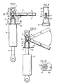
- Figure 11 est une vue partielle en élévation du dispositif selon l'invention, prise selon l'axe du levier.
- Figure 1 is a sectional view of a device according to the invention with direct control associated with the end of the body of a gas spring.
- Figure 2 is a similar section of a device associated with the rod of a gas spring.
- Figure 3 is a view along arrow III of Figure 1.
- Figure 4 is a view similar to Figure 1, but with a cable control.
- Figure 5 is a sectional view, similar to that of Figures 1, 2 and 4 of the nozzle, in another embodiment.
- Figure 6 is a view, similar to Figure 3, of the nozzle of Figure 5.
- Figures 7, 8 and 9 are top, side and cross-sectional views of the lever at the end of the cable attachment.
- Figure 10 is a sectional view along line XX of Figure 1.
- Figure 11 is a partial elevational view of the device according to the invention, taken along the axis of the lever.
Les figures 1 et 2 montrent un embout combiné 1 en coupe longitudinale monté sur un ressort à gaz blocable.Figures 1 and 2 show a combined tip 1 in longitudinal section mounted on a lockable gas spring.
Sur la figure 1, l'embout combiné 1 est vissé sur l'embout fileté 7 d'un ressort à gaz blocable 11 dont las commande est située côté fond de tube (à l'opposé de la tige). Le levier de commande 2 est en position neutre, il est maintenu sur les appuis 4 et 5 par le doigt de commande 6 du ressort à gaz blocable. Une plaque 9 munie d'un trou 9a prévu pour l'arrêt de gaine 18 fixée à la base de l'embout combiné 1. Le doigt de commande 6 est légèrement précontraint par la partie élargie 24 du levier de commande d2, située entre deux parties plus minces 25, 26 correspondant aux appuis 4 et 5. L'embout combiné 1 comporte un trou débouchant 3 percé radialement permettant la fixation du ressort à gaz sur un axe.In FIG. 1, the combined end piece 1 is screwed onto the threaded
Sur la figure 2, l'embout combiné 1 est vissé sur la tige 8 d'un ressort à gaz blocable 12 dont le doigt de commande 6 est situé à l'extrémité de cette tige. Le levier 2 est actionné, le doigt de commande est enfoncé par la partie élargie 24. Le levier prend appui sur le point 5 de l'embout lorsqu'il est poussé, et sur le point 4 lorsqu'il est tiré.In FIG. 2, the combined end piece 1 is screwed onto the
La plaque 9 est fixée par sertissage sur la base de l'embout combiné 1. La partie élargie 24 du levier 2 a une double fonction : elle sollicite le doigt de commande 6 et, elle retient prisonnier le levier 2 dans l'embout combiné 1 tout en permettant le débattement nécessaire pour la manoeuvre.The
Dans la figure 3, la fente 14 réalisée en forme de boutonnière rétrécie en haut est percée radialement de part en part dans l'embout combiné 1. La partie élargie 24 du levier 2 passe par la boutonnière, les deux sections réduites 25 et 26 de ce levier coulissent dans la fente correspondante de la partie haute de cette boutonnière.In FIG. 3, the
On aperçoit, sur la figure 3, le sommet de l'embout fileté 7 à travers la fente 14. On comprend que la position relative de ce sommet et des portions élargies des fentes est calculée pour empêcher la partie élargie 24 d'atteindre ces portions élargies des fentes, et que lorsqu'on dévisse l'embout combiné 1 fixé sur l'embout fileté 7, on libère le levier, dont la partie élargie traverse alors la fente sans difficulté.We can see, in FIG. 3, the top of the threaded
Les leviers 2 ou 15 sont donc mis en place dans l'embout combiné 1 avant montage de cet embout sur le ressort à gaz blocable 11 ou 12The
La figure 10 montre une section transversale de l'embout combiné 1.FIG. 10 shows a cross section of the combined tip 1.
La figure 4 montre une section longitudinale de l'embout combiné 1 équipé d'un levier 15 permettant la commande à distance au moyen d'un câble souple 17 et d'une gaine 19.FIG. 4 shows a longitudinal section of the combined end piece 1 fitted with a
Le levier 15 est muni d'un moyen pour bloquer le câble, ici le câble passe dans un trou radial, une vis 16 montée axialement dans un trou sécant vient immobiliser ce câble.The
Les figures 7 à 9 montrent une autre forme de bloquage du câble : un tourillon 22 muni d'une vis 23 bloque le câble 17. Ce tourillon est monté libre dans le trou 20 du levier 15, le câble passe à travers la fente 21 et immobilise transversalement le tourillon. Ce montage est connu dans les cycles pour la commande de freins.FIGS. 7 to 9 show another form of cable blocking: a
Les figures 5 et 6 montrent une autre réalisation de l'embout combiné par moulage.Figures 5 and 6 show another embodiment of the combined tip by molding.
Sur la figure 11 un embout combiné 1, pourvu d'un filetage femelle, est vissé sur un embout fileté 7, qui prolonge un ressort à gaz non représenté. Une fente 14 traverse l'embout combiné 1. Elle comporte une portion de faible section transversale 14A, située du côté opposé à l'embout fileté 7, et une portion élargie 14B, plus proche de l'embout 7. La largeur de la portion amincie 14A est légèrement supérieure d'une section mince 25 du levier de commande, et la partie élargie 14B a une section légèrement supérieure au diamètre de la partie élargie 24 du même levier.In FIG. 11, a combined end piece 1, provided with a female thread, is screwed onto a threaded
Dans la position représentée, le levier est forcé en direction de l'embout 7, et il vient buter sur celui-ci par l'intermédiaire du doigt de commande 6, qui est lui-même en position d'enfoncement maximal. Sur la figure, on aperçoit l'extrémité de l'embout 7 et du doigt de commande 6, et on constate que la partie élargie 24 du levier se trouve en partie au droit de la portion amincie 14A de la fente, si bien que le levier ne peut pas passer à travers la fente. On constate aisément que, après dévissage relatif de l'embout combiné 1 et de l'embout fileté 7 sur une longueur suffisante, la partie élargie 25 du levier pourra se trouver entièrement en face de la portion élargie 14B de la fente et que le levier pourra alors être extrait.In the position shown, the lever is forced in the direction of the
Pour le montage, on met d'abord en place le levier dans l'embout combiné en le faisant passer à travers les fenêtres 14, après quoi on visse l'embout combiné 1 et l'embout fileté 7 l'un sur l'autre. Le levier est alors bloqué et ne peut s'échapper.For assembly, the lever is first put into place in the combined end-piece by passing it through the
L'embout combiné 1 peut être réalisé sous différentes formes sans modifier l'originalité de l'invention :
- a) le moyen de
fixation 3 qui est un trou radial peut être soit une rotule, soit un filetage, soit une pince, soit une queue cylindrique, conique etc, - b) le moyen de fixation sur le ressort à gaz est le plus souvent un filetage, il peut aussi se fixer soit par sertissage, soit par pincement, soit par goupillage etc,
- c) la plaque d'arrêt de la gaine 9 peut être solidaire de l'embout combiné 1, (figure 5) ou rapportée (figure 1) ; elle peut être amovible et mise en place au choix.
- a) the fixing means 3 which is a radial hole can be either a ball joint, a thread, or a clamp, or a cylindrical, conical tail, etc.
- b) the fixing means on the gas spring is most often a thread, it can also be fixed either by crimping, or by pinching, or by pinning, etc.
- c) the
sheath stop plate 9 may be integral with the combined end piece 1, (FIG. 5) or attached (FIG. 1); it can be removable and set up as desired.
L'invention apporte aux utilisateurs de ressort à gaz blocable, un moyen simple et peu coûteux pour réaliser une commande soit directe soit à distance avec un nombre de pièces réduit, le levier peut être actionné soit en poussant, soit en tirant, l'effort de commande est réduit grâce au rapport des bras de levier.The invention provides users of a lockable gas spring with a simple and inexpensive means of carrying out control either directly or remotely with a reduced number of parts, the lever can be actuated either by pushing or by pulling the force control is reduced by the ratio of the lever arms.
Lors d'une commande à distance par câble, si les frottements entre le câble et la gaine sont importants, on peut ajouter entre la plaque d'arrêt de la gaine et le levier de manoeuvre un ressort de compression favorisant le retour à la position initiale.During a remote control by cable, if the friction between the cable and the sheath is important, one can add between the sheath stop plate and the operating lever a compression spring favoring the return to the initial position .
En conclusion l'invention apporte les avantages suivants :
- Le levier se monte dans l'embout avant montage de l'embout sur le ressort à gaz.
- Le levier est prisonnier radialement dans l'embout lorsqu'il se trouve dans la portion étroite 14A de la fente 14.
- Le levier est prisonnier axialement et radialement dans l'embout, lorsque l'embout est monté sur le ressort à gaz.
- La forme particulière de la fente 14 réalisée au travers de l'embout permet au levier d'être manoeuvrable aussi bien en poussant qu'en tirant dans un plan passant par l'axe du ressort à gaz.
- Le levier peut se déplacer librement dans la portion étroite 14A de la fente 14 afin d'assurer la manoeuvre axiale du doigt de commande.
- Le levier peut être manoeuvré soit directement, soit par un câble souple coulissant dans une gaine, cette gaine prenant appui sur une forme solidaire de l'embout.
- L'embout et le levier sont de réalisation très simple, avec des moyens courants.
- L'embout peut être adapté très facilement sur des montages existants par différents procédés (trous, axe, rotule,filetage, taraudage, queue cylindrique etc).In conclusion, the invention provides the following advantages:
- The lever is mounted in the end piece before mounting the end piece on the gas spring.
- The lever is trapped radially in the end piece when it is in the narrow portion 14A of the
- The lever is trapped axially and radially in the nozzle, when the nozzle is mounted on the gas spring.
- The particular shape of the
- The lever can move freely in the narrow portion 14A of the
- The lever can be operated either directly or by a flexible cable sliding in a sheath, this sheath bearing on a form integral with the end piece.
- The tip and the lever are very simple, with common means.
- The end piece can be easily adapted to existing assemblies by different methods (holes, axis, ball joint, thread, tapping, cylindrical shank, etc.).
Claims (6)
Priority Applications (1)
| Application Number | Priority Date | Filing Date | Title |
|---|---|---|---|
| AT89402612T ATE82623T1 (en) | 1988-09-30 | 1989-09-25 | CONTROL DEVICE FOR A LOCKABLE GAS SPRING. |
Applications Claiming Priority (2)
| Application Number | Priority Date | Filing Date | Title |
|---|---|---|---|
| FR8812797A FR2637395B1 (en) | 1988-09-30 | 1988-09-30 | CONTROL DEVICE FOR LOCKABLE GAS SPRING |
| FR8812797 | 1988-09-30 |
Publications (2)
| Publication Number | Publication Date |
|---|---|
| EP0362038A1 true EP0362038A1 (en) | 1990-04-04 |
| EP0362038B1 EP0362038B1 (en) | 1992-11-19 |
Family
ID=9370562
Family Applications (1)
| Application Number | Title | Priority Date | Filing Date |
|---|---|---|---|
| EP89402612A Expired - Lifetime EP0362038B1 (en) | 1988-09-30 | 1989-09-25 | Control device for a blockable gas spring |
Country Status (7)
| Country | Link |
|---|---|
| US (1) | US4989698A (en) |
| EP (1) | EP0362038B1 (en) |
| AT (1) | ATE82623T1 (en) |
| CA (1) | CA1329400C (en) |
| DE (1) | DE68903549T2 (en) |
| ES (1) | ES2036361T3 (en) |
| FR (1) | FR2637395B1 (en) |
Cited By (7)
| Publication number | Priority date | Publication date | Assignee | Title |
|---|---|---|---|---|
| EP0411623A2 (en) * | 1989-08-04 | 1991-02-06 | NEMO S.p.A. | Shutter opening device particularly for pleasure craft hatchways |
| EP0517546A1 (en) * | 1991-06-06 | 1992-12-09 | Aveling Barford (Machines) Plc | Improvements in and relating to vehicle suspensions |
| FR2696516A1 (en) * | 1992-10-07 | 1994-04-08 | Rhonalp Tech Soudure | Device for controlling operation of gas jack - comprises body with axial bore and transverse oblong bore, shaft with machined part having spherical portion and two cylindrical portions |
| EP0789157A3 (en) * | 1996-02-10 | 1999-02-03 | SUSPA COMPART Aktiengesellschaft | Length-adjustable gas spring |
| KR100442536B1 (en) * | 2001-08-28 | 2004-08-04 | 이종환 | Operation levers mounting structure of swivel chair |
| WO2015010673A3 (en) * | 2013-07-23 | 2016-07-21 | Guido Wandschneider | Device for triggering a gas spring |
| CN109210121A (en) * | 2017-07-07 | 2019-01-15 | 苏斯帕有限公司 | For manipulate can locking gas spring device and column with this device |
Families Citing this family (14)
| Publication number | Priority date | Publication date | Assignee | Title |
|---|---|---|---|---|
| DE3934960A1 (en) * | 1989-10-20 | 1991-04-25 | Stabilus Gmbh | RELEASE DEVICE FOR PNEUMATIC AND HYDROPNEUMATIC HEIGHT ADJUSTMENT DEVICES |
| TW242109B (en) * | 1992-08-20 | 1995-03-01 | Ciba Geigy | |
| US5435529A (en) * | 1993-11-30 | 1995-07-25 | Cable Manufacturing & Assembly Co., Inc. | Cable control actuator for a locking gas spring |
| DE19626844C2 (en) * | 1996-07-04 | 1999-02-25 | Wandschneider Ingeborg | Device for triggering a gas spring |
| DE19548139C2 (en) * | 1995-12-21 | 1998-09-24 | Stabilus Gmbh | Gas spring with adjustable end position |
| US5909890A (en) * | 1996-09-11 | 1999-06-08 | Sachs; Gregory D. | Device for locking and unlocking bicycle suspension systems |
| DE19904206C5 (en) * | 1999-02-03 | 2004-09-30 | Zf Sachs Ag | Junction bearing with a line connection |
| US6736360B1 (en) * | 2003-01-27 | 2004-05-18 | Alcon, Inc. | Rotary jointed arm for a surgical tray |
| ES2267353B1 (en) * | 2004-07-14 | 2008-03-01 | Jose Javier Barandiaran Salaverria | GAS CYLINDER WITH PIVOT. |
| US20070284495A1 (en) * | 2006-06-13 | 2007-12-13 | Charles Steven T | Tray Mounting System |
| JP2009543131A (en) * | 2006-06-28 | 2009-12-03 | アルコン,インコーポレイティド | Control display positioning system |
| US7461825B2 (en) * | 2006-09-18 | 2008-12-09 | Alcon, Inc. | Tray support arm assembly |
| US9580123B2 (en) * | 2015-06-02 | 2017-02-28 | Shimano Inc. | Bicycle seatpost assembly |
| CN106090100B (en) * | 2016-08-11 | 2018-02-06 | 北京磊焱氮气弹簧技术研究所 | A kind of compression gas spring of any lockable device |
Citations (7)
| Publication number | Priority date | Publication date | Assignee | Title |
|---|---|---|---|---|
| FR1502431A (en) * | 1965-11-24 | 1967-11-18 | Hydraulic adjustable support system and device for its implementation | |
| FR2350075A1 (en) * | 1976-05-06 | 1977-12-02 | Montessuit Leon | Telescopic self-adjusting height variable chair leg - is sprung piston-cylinder controlled by passive hydraulic jack with lever valve |
| CH619604A5 (en) * | 1977-08-25 | 1980-10-15 | Fehlbaum & Co | Apparatus for adjusting the seat height on a swivel chair |
| FR2461851A1 (en) * | 1979-07-19 | 1981-02-06 | Stabilus Gmbh | Gas strut controlled by e.g. bowden cable - uses piston valve operated push rod in hollow piston rod with radial bore for trans piston gas transfer |
| FR2488499A1 (en) * | 1980-08-13 | 1982-02-19 | Mirima | Jack actuated telescopic column for adjustable chair - uses cranked feet to locate rockable horizontal foot operated wheel which controls operation of jack |
| EP0050465A1 (en) * | 1980-10-17 | 1982-04-28 | Kayaba Kogyo Kabushiki Kaisha | A height control mechanism for a chair, table or the like |
| DE3325798A1 (en) * | 1983-07-16 | 1985-01-24 | Friedrich W. Dauphin, Bürositzmöbelfabrik, 8561 Offenhausen | Gas spring, in particular for adjusting backrests of chairs, such as office swivel chairs and the like |
Family Cites Families (5)
| Publication number | Priority date | Publication date | Assignee | Title |
|---|---|---|---|---|
| DE1955308U (en) * | 1966-12-08 | 1967-02-09 | Franz Kiel G M B H | DEVICE FOR HOLDING AND ADJUSTING BACKRESTS ON VEHICLE SEATS. |
| DE6910925U (en) * | 1969-08-18 | 1969-11-20 | Wilde & Spieth Fa | TELESCOPIC TUBE PILLAR FOR FURNITURE |
| DE1955308C3 (en) * | 1969-11-04 | 1978-05-24 | Raoul Dipl.-Ing. 8992 Hengnau Joern | Rubber-metal articulated bush |
| JPS52159313U (en) * | 1976-05-28 | 1977-12-03 | ||
| US4420066A (en) * | 1981-09-10 | 1983-12-13 | General Signal Corporation | Cam lock slack adjuster |
-
1988
- 1988-09-30 FR FR8812797A patent/FR2637395B1/en not_active Expired - Fee Related
-
1989
- 1989-09-21 US US07/410,260 patent/US4989698A/en not_active Expired - Lifetime
- 1989-09-25 ES ES198989402612T patent/ES2036361T3/en not_active Expired - Lifetime
- 1989-09-25 EP EP89402612A patent/EP0362038B1/en not_active Expired - Lifetime
- 1989-09-25 CA CA000612716A patent/CA1329400C/en not_active Expired - Fee Related
- 1989-09-25 DE DE8989402612T patent/DE68903549T2/en not_active Expired - Lifetime
- 1989-09-25 AT AT89402612T patent/ATE82623T1/en not_active IP Right Cessation
Patent Citations (7)
| Publication number | Priority date | Publication date | Assignee | Title |
|---|---|---|---|---|
| FR1502431A (en) * | 1965-11-24 | 1967-11-18 | Hydraulic adjustable support system and device for its implementation | |
| FR2350075A1 (en) * | 1976-05-06 | 1977-12-02 | Montessuit Leon | Telescopic self-adjusting height variable chair leg - is sprung piston-cylinder controlled by passive hydraulic jack with lever valve |
| CH619604A5 (en) * | 1977-08-25 | 1980-10-15 | Fehlbaum & Co | Apparatus for adjusting the seat height on a swivel chair |
| FR2461851A1 (en) * | 1979-07-19 | 1981-02-06 | Stabilus Gmbh | Gas strut controlled by e.g. bowden cable - uses piston valve operated push rod in hollow piston rod with radial bore for trans piston gas transfer |
| FR2488499A1 (en) * | 1980-08-13 | 1982-02-19 | Mirima | Jack actuated telescopic column for adjustable chair - uses cranked feet to locate rockable horizontal foot operated wheel which controls operation of jack |
| EP0050465A1 (en) * | 1980-10-17 | 1982-04-28 | Kayaba Kogyo Kabushiki Kaisha | A height control mechanism for a chair, table or the like |
| DE3325798A1 (en) * | 1983-07-16 | 1985-01-24 | Friedrich W. Dauphin, Bürositzmöbelfabrik, 8561 Offenhausen | Gas spring, in particular for adjusting backrests of chairs, such as office swivel chairs and the like |
Cited By (11)
| Publication number | Priority date | Publication date | Assignee | Title |
|---|---|---|---|---|
| EP0411623A2 (en) * | 1989-08-04 | 1991-02-06 | NEMO S.p.A. | Shutter opening device particularly for pleasure craft hatchways |
| EP0411623A3 (en) * | 1989-08-04 | 1991-08-21 | Nemo S.P.A. | Shutter opening device particularly for pleasure craft hatchways |
| EP0517546A1 (en) * | 1991-06-06 | 1992-12-09 | Aveling Barford (Machines) Plc | Improvements in and relating to vehicle suspensions |
| FR2696516A1 (en) * | 1992-10-07 | 1994-04-08 | Rhonalp Tech Soudure | Device for controlling operation of gas jack - comprises body with axial bore and transverse oblong bore, shaft with machined part having spherical portion and two cylindrical portions |
| EP0789157A3 (en) * | 1996-02-10 | 1999-02-03 | SUSPA COMPART Aktiengesellschaft | Length-adjustable gas spring |
| KR100442536B1 (en) * | 2001-08-28 | 2004-08-04 | 이종환 | Operation levers mounting structure of swivel chair |
| WO2015010673A3 (en) * | 2013-07-23 | 2016-07-21 | Guido Wandschneider | Device for triggering a gas spring |
| CN106104063A (en) * | 2013-07-23 | 2016-11-09 | 吉多·万德施奈德 | For triggering the equipment of gas spring |
| CN106104063B (en) * | 2013-07-23 | 2018-04-10 | 吉多·万德施奈德 | Equipment for triggering gas spring |
| US10072721B2 (en) | 2013-07-23 | 2018-09-11 | Guido Wandschneider | Device for triggering a gas spring |
| CN109210121A (en) * | 2017-07-07 | 2019-01-15 | 苏斯帕有限公司 | For manipulate can locking gas spring device and column with this device |
Also Published As
| Publication number | Publication date |
|---|---|
| US4989698A (en) | 1991-02-05 |
| FR2637395A1 (en) | 1990-04-06 |
| DE68903549T2 (en) | 1993-06-03 |
| CA1329400C (en) | 1994-05-10 |
| FR2637395B1 (en) | 1990-12-28 |
| DE68903549D1 (en) | 1992-12-24 |
| ES2036361T3 (en) | 1993-05-16 |
| EP0362038B1 (en) | 1992-11-19 |
| ATE82623T1 (en) | 1992-12-15 |
Similar Documents
| Publication | Publication Date | Title |
|---|---|---|
| EP0362038B1 (en) | Control device for a blockable gas spring | |
| EP1486294B1 (en) | Extension pole for actuating a hand-held tool | |
| EP2243972B1 (en) | Attachment link with lockable rotatory ring | |
| EP0861140B1 (en) | Coupling device and rotary drive tool therefor | |
| FR2626163A1 (en) | GUIDING DEVICE FOR A LASER FIBER | |
| EP0547942A1 (en) | Quick acting coupling device for the sealed connection between two tubes or two rigid or semi-rigid pipes | |
| WO2002052932A1 (en) | Crossbow-type underwater gun comprising a stretching device | |
| EP1673530B1 (en) | Thrust reverser lock comprising locking device | |
| EP1213038B1 (en) | Fire hose comprising a safety device to prevent it from moving under the action of water ensuring its feeding | |
| FR2866045A1 (en) | Control knob for safety lock of e.g. protective barrier, has spring supported between core and casing through antifriction stop, and two locking units that are engaged to integrate casing and core for controlling opening of lock | |
| EP0770745B1 (en) | Detachable handle for a door or a window especially in metallic frame | |
| FR2617920A2 (en) | Device for mechanically controlling a cable with manual adjustment | |
| EP3416880B1 (en) | Adjustable compression suspension kit for a vehicle | |
| FR2943359A1 (en) | SAFETY DEVICE FOR AT LEAST ONE BUFFER, IN PARTICULAR A PAVEMENT LOOK | |
| FR2543510A1 (en) | Telescopic wishbone of adjustable length for sailboard | |
| FR2712062A1 (en) | Device designed for passing a pipe through a wall | |
| FR2564395A1 (en) | SEAT BELT REEL | |
| FR2526070A1 (en) | Extrusion gun for mastic - has coupling which prevents continuation of mastic flow when handle is released | |
| EP3682992B1 (en) | Drilling device for a pipe | |
| FR2717539A1 (en) | Blocking device for given position of tube sliding in another for regulating length of assembly such as camera tripod | |
| EP2349621B1 (en) | Bow saw mounting and corresponding bow saw | |
| FR3138111A1 (en) | Vehicle comprising an actuation system provided with a guiding member | |
| FR2908063A1 (en) | Metallic fitting positioning device, has manual push unit i.e. handle, internal surface, gripping extension, activating piston such that piston exerts effort on metallic fitting to force fitting in open end of tube | |
| WO1995009529A1 (en) | Device for securing a reel to a fishing rod | |
| FR2691044A1 (en) | Reel for mounting on fishing rod - Has elongated form, where width is practically same dimension as diameter of rod |
Legal Events
| Date | Code | Title | Description |
|---|---|---|---|
| PUAI | Public reference made under article 153(3) epc to a published international application that has entered the european phase |
Free format text: ORIGINAL CODE: 0009012 |
|
| AK | Designated contracting states |
Kind code of ref document: A1 Designated state(s): AT BE CH DE ES FR GB IT LI LU NL SE |
|
| 17P | Request for examination filed |
Effective date: 19900917 |
|
| 17Q | First examination report despatched |
Effective date: 19910322 |
|
| GRAA | (expected) grant |
Free format text: ORIGINAL CODE: 0009210 |
|
| AK | Designated contracting states |
Kind code of ref document: B1 Designated state(s): AT BE CH DE ES FR GB IT LI LU NL SE |
|
| REF | Corresponds to: |
Ref document number: 82623 Country of ref document: AT Date of ref document: 19921215 Kind code of ref document: T |
|
| REF | Corresponds to: |
Ref document number: 68903549 Country of ref document: DE Date of ref document: 19921224 |
|
| ITF | It: translation for a ep patent filed |
Owner name: STUDIO CONS. BREVETTUALE S.R.L. |
|
| GBT | Gb: translation of ep patent filed (gb section 77(6)(a)/1977) |
Effective date: 19930107 |
|
| REG | Reference to a national code |
Ref country code: ES Ref legal event code: FG2A Ref document number: 2036361 Country of ref document: ES Kind code of ref document: T3 |
|
| PLBE | No opposition filed within time limit |
Free format text: ORIGINAL CODE: 0009261 |
|
| STAA | Information on the status of an ep patent application or granted ep patent |
Free format text: STATUS: NO OPPOSITION FILED WITHIN TIME LIMIT |
|
| PG25 | Lapsed in a contracting state [announced via postgrant information from national office to epo] |
Ref country code: AT Effective date: 19930925 |
|
| PG25 | Lapsed in a contracting state [announced via postgrant information from national office to epo] |
Ref country code: SE Effective date: 19930926 |
|
| PG25 | Lapsed in a contracting state [announced via postgrant information from national office to epo] |
Ref country code: LU Free format text: LAPSE BECAUSE OF NON-PAYMENT OF DUE FEES Effective date: 19930930 Ref country code: BE Effective date: 19930930 |
|
| PGFP | Annual fee paid to national office [announced via postgrant information from national office to epo] |
Ref country code: CH Payment date: 19931008 Year of fee payment: 5 |
|
| 26N | No opposition filed | ||
| BERE | Be: lapsed |
Owner name: AIRAX Effective date: 19930930 |
|
| PG25 | Lapsed in a contracting state [announced via postgrant information from national office to epo] |
Ref country code: NL Effective date: 19940401 |
|
| NLV4 | Nl: lapsed or anulled due to non-payment of the annual fee | ||
| PG25 | Lapsed in a contracting state [announced via postgrant information from national office to epo] |
Ref country code: LI Effective date: 19940930 Ref country code: CH Effective date: 19940930 |
|
| EUG | Se: european patent has lapsed |
Ref document number: 89402612.9 Effective date: 19940410 |
|
| REG | Reference to a national code |
Ref country code: CH Ref legal event code: PL |
|
| REG | Reference to a national code |
Ref country code: GB Ref legal event code: IF02 |
|
| PGFP | Annual fee paid to national office [announced via postgrant information from national office to epo] |
Ref country code: GB Payment date: 20030924 Year of fee payment: 15 |
|
| PGFP | Annual fee paid to national office [announced via postgrant information from national office to epo] |
Ref country code: DE Payment date: 20031002 Year of fee payment: 15 |
|
| PGFP | Annual fee paid to national office [announced via postgrant information from national office to epo] |
Ref country code: ES Payment date: 20031021 Year of fee payment: 15 |
|
| PGFP | Annual fee paid to national office [announced via postgrant information from national office to epo] |
Ref country code: FR Payment date: 20031027 Year of fee payment: 15 |
|
| PG25 | Lapsed in a contracting state [announced via postgrant information from national office to epo] |
Ref country code: GB Free format text: LAPSE BECAUSE OF NON-PAYMENT OF DUE FEES Effective date: 20040925 |
|
| PG25 | Lapsed in a contracting state [announced via postgrant information from national office to epo] |
Ref country code: ES Free format text: LAPSE BECAUSE OF NON-PAYMENT OF DUE FEES Effective date: 20040927 |
|
| PG25 | Lapsed in a contracting state [announced via postgrant information from national office to epo] |
Ref country code: DE Free format text: LAPSE BECAUSE OF NON-PAYMENT OF DUE FEES Effective date: 20050401 |
|
| GBPC | Gb: european patent ceased through non-payment of renewal fee |
Effective date: 20040925 |
|
| PG25 | Lapsed in a contracting state [announced via postgrant information from national office to epo] |
Ref country code: FR Free format text: LAPSE BECAUSE OF NON-PAYMENT OF DUE FEES Effective date: 20050531 |
|
| REG | Reference to a national code |
Ref country code: FR Ref legal event code: ST |
|
| PG25 | Lapsed in a contracting state [announced via postgrant information from national office to epo] |
Ref country code: IT Free format text: LAPSE BECAUSE OF NON-PAYMENT OF DUE FEES Effective date: 20050925 |
|
| REG | Reference to a national code |
Ref country code: ES Ref legal event code: FD2A Effective date: 20040927 |