EP3682992B1 - Drilling device for a pipe - Google Patents
Drilling device for a pipe Download PDFInfo
- Publication number
- EP3682992B1 EP3682992B1 EP20152517.7A EP20152517A EP3682992B1 EP 3682992 B1 EP3682992 B1 EP 3682992B1 EP 20152517 A EP20152517 A EP 20152517A EP 3682992 B1 EP3682992 B1 EP 3682992B1
- Authority
- EP
- European Patent Office
- Prior art keywords
- shaft
- cam
- drilling
- cam follower
- cutting tool
- Prior art date
- Legal status (The legal status is an assumption and is not a legal conclusion. Google has not performed a legal analysis and makes no representation as to the accuracy of the status listed.)
- Active
Links
- 238000005553 drilling Methods 0.000 title claims description 104
- 230000007246 mechanism Effects 0.000 claims description 51
- 230000006835 compression Effects 0.000 claims description 26
- 238000007906 compression Methods 0.000 claims description 26
- 238000000034 method Methods 0.000 claims description 16
- 230000000903 blocking effect Effects 0.000 claims description 6
- 230000003247 decreasing effect Effects 0.000 claims description 6
- 239000000843 powder Substances 0.000 claims description 6
- 238000006073 displacement reaction Methods 0.000 claims description 5
- 230000008878 coupling Effects 0.000 claims description 4
- 238000010168 coupling process Methods 0.000 claims description 4
- 238000005859 coupling reaction Methods 0.000 claims description 4
- 229910003460 diamond Inorganic materials 0.000 claims description 3
- 239000010432 diamond Substances 0.000 claims description 3
- 239000007788 liquid Substances 0.000 claims description 3
- 208000031968 Cadaver Diseases 0.000 description 29
- XLYOFNOQVPJJNP-UHFFFAOYSA-N water Substances O XLYOFNOQVPJJNP-UHFFFAOYSA-N 0.000 description 9
- 238000012550 audit Methods 0.000 description 5
- 230000000284 resting effect Effects 0.000 description 5
- 229920000297 Rayon Polymers 0.000 description 4
- 241001080024 Telles Species 0.000 description 4
- 230000005540 biological transmission Effects 0.000 description 4
- 239000002964 rayon Substances 0.000 description 4
- 208000027418 Wounds and injury Diseases 0.000 description 3
- 230000006378 damage Effects 0.000 description 3
- 208000014674 injury Diseases 0.000 description 3
- 239000002184 metal Substances 0.000 description 3
- 229910052751 metal Inorganic materials 0.000 description 3
- 239000012530 fluid Substances 0.000 description 2
- 229910052697 platinum Inorganic materials 0.000 description 2
- 239000002699 waste material Substances 0.000 description 2
- 101100008050 Caenorhabditis elegans cut-6 gene Proteins 0.000 description 1
- 241000238814 Orthoptera Species 0.000 description 1
- 230000009471 action Effects 0.000 description 1
- 230000004075 alteration Effects 0.000 description 1
- 230000008859 change Effects 0.000 description 1
- 230000007547 defect Effects 0.000 description 1
- 230000001419 dependent effect Effects 0.000 description 1
- 229940082150 encore Drugs 0.000 description 1
- 230000005484 gravity Effects 0.000 description 1
- 230000008569 process Effects 0.000 description 1
- 238000011084 recovery Methods 0.000 description 1
- 238000010079 rubber tapping Methods 0.000 description 1
- 230000001360 synchronised effect Effects 0.000 description 1
Images


Classifications
-
- F—MECHANICAL ENGINEERING; LIGHTING; HEATING; WEAPONS; BLASTING
- F16—ENGINEERING ELEMENTS AND UNITS; GENERAL MEASURES FOR PRODUCING AND MAINTAINING EFFECTIVE FUNCTIONING OF MACHINES OR INSTALLATIONS; THERMAL INSULATION IN GENERAL
- F16L—PIPES; JOINTS OR FITTINGS FOR PIPES; SUPPORTS FOR PIPES, CABLES OR PROTECTIVE TUBING; MEANS FOR THERMAL INSULATION IN GENERAL
- F16L41/00—Branching pipes; Joining pipes to walls
- F16L41/04—Tapping pipe walls, i.e. making connections through the walls of pipes while they are carrying fluids; Fittings therefor
- F16L41/06—Tapping pipe walls, i.e. making connections through the walls of pipes while they are carrying fluids; Fittings therefor making use of attaching means embracing the pipe
Definitions
- the invention relates to a drilling device suitable for drilling a pipe under load (or not) such as for example a pipe carrying water, as well as a method of drilling a pipe using such a drilling device.
- bypass collars which traditionally include a saddle equipped with a valve and a flange (flexible or rigid). Conventionally, this type of collar is mounted on a water pipe under load (or not), the flexible flange being deformed to surround the pipe, the saddle resting on an outer wall of the pipe.
- the field of the invention is more particularly that of piercing devices used to pierce the wall of the pipe in line with the valve, and through the tubing of the latter, once the bypass collar is in place.
- drilling devices specially configured for this use, namely suitable for drilling a pipe under load, which include a connection part configured to be removably attached to a valve. of a bypass collar as well as a movable cutting tool with respect to said connection part, configured to pass through said valve while ensuring the drilling of the pipe.
- such a drilling device comprises a connection part which is fixed to the valve of the collar, in a rigid manner, as well as a tool-holder shaft, coupled to a cutting tool, intended to pass through the valve to attack the pipeline.
- the tool-holder shaft is linked mechanically to the connection part by a screwing system.
- the document WO 99/32823 teaches such a drilling technique. Drilling of the pipe is obtained by rotating, manually or motorized, the tool-holder shaft. This rotation causes the joint rotation of the cutting tool and its advancement by a displacement dependent on the screw pitch of said screwing system. Such a drilling technique is widely used for drilling pipes under load.
- this drilling technique has the non-negligible drawback that it imposes significant forces on the branch collar to which the drilling device is linked, which makes it necessary to oversize the branch collar and its flange in order to resist the mechanical stresses imposed by drilling operations.
- the drilling technique according to WO 99/32823 generates chips, which, because of their large size, are likely to degrade equipment such as water meters, when this waste is carried in the pipe, downstream by the circulating fluid or even the elements of 'blocking of the take-over valve, for example.
- the drilling device according to the document FR 2 984 780 , which discloses a drilling device according to the preamble of claim 1, provides significant progress to address this problem in that its structure makes it possible to dissociate the rotation applied by the shaft carrying the cutting tool, which is driven in rotation by motor means, on the one hand, the thrust force applied by the cutting tool which is provided only by elastic means, and in particular by a coil spring used in compression, on the other hand.
- the drilling force thus never exceeds that imposed by the elastic means: it is ensured that the drilling force does not alter the bypass collar on which the drilling device is attached.
- the releasable loading means are provided between the body and the first part.
- these means comprise clamping clamps secured to the first part, and coming to bear on a flange of the body to pull the first part by compressing a compression spring.
- these means comprise two cam levers, each pivotally articulated with respect to the body, and two rollers integral with the first part configured to cooperate with the cam.
- the compression of the coil spring and therefore the loading of the elastic means takes place by pulling the first part by applying a force between the body and the first part, and in the direction opposite to the drilling direction, thanks to clamping clamps, or even thanks to cam / roller lever systems.
- clamping clamp or the pair of cam levers / rollers ensures a locking of the first part relative to the body in this position of compression of the elastic means, and while the shaft carrying the cutting tool is not still not in place in the faucet, as well as in the components of the drilling device linked to this faucet.
- the shaft and the cutting tool are not secured to the second part via the fixing means until after this compression step, by bringing the cutting tool into abutment against the pipe.
- the drilling process requires a certain number of steps which cannot be reduced, and in particular successively a step of loading the elastic means, a step of fixing the shaft and the shaft. 'cutting tool, but also a step of releasing the elastic means so that the latter force the cutting tool against the pipe.
- this number of steps before drilling slows down the implementation during drilling, and can be the source of error for the operator.
- the problem to which the invention responds is first of all to propose a drilling device the structure of which is configured for the drilling under load of a pipe minimizing the forces on the pipe, like that of the document FR 2 984 780 , but the implementation of which is faster and easier than that of this prior art.
- Another object of the present invention is to provide such a piercing device which minimizes the risk of injury, by preventing empty charging of the elastic means of the piercing device.
- Another object of the present invention is to provide, at least according to one embodiment, such a drilling device minimizing the risks of pinching when loading the elastic means.
- the drilling device allows the compression of said elastic means, during the passage of the operating mechanism from the rest position to the working position, only when the cutting tool is in abutment against the pipe, and that the The tree is attached to the second part.
- the first part may comprise a tube, coaxial with the shaft and traversed by said shaft, and in which the elastic means comprise a coil spring mounted around the tube, a projecting shoulder forming a seat for one end of the coil spring, l 'other end of the coil spring resting on a seat formed on the third part.
- the operating mechanism may include a control lever, pivotally articulated on the third part, as well as a cam and cam follower pair distributed between the body and the control lever, the cam follower being integral with the body and the cam integral with the base of the control lever, said operating mechanism being configured to take said rest position corresponding to a first relative position of the cam with respect to the cam follower, and said working position, obtained by pivoting of the control lever , and corresponding to a second relative position of the cam by relative to the cam follower, and wherein the cam comprises a cam track formed on a base portion of the control lever, the path being of variable radius with respect to the axis of rotation of the substantially decreasing radius control lever to the cam follower between the rest position and the working position of the operating mechanism in order to force the third part from the position remote from the connection part to the close position of the connection part.
- the cam track has two end stops for said cam follower; with a first stop for the cam follower in the rest position of the operating mechanism and a second stop for the cam follower in the operating position of the operating mechanism.
- the cam track may have a decreasing radius with respect to the axis of rotation for the cam follower, immediately before the second limit switch and then a sharply increasing radius when said cam follower reaches said second limit switch, in order to constitute a stable position for the cam follower in the cam track in said operating position of the operating mechanism
- the cam and the cam follower of the operating mechanism can advantageously be housed in a casing configured in order to prevent the risk of pinching between the cam and the cam follower.
- the cam follower may be a roller pivotally articulated on the body along a pivot axis substantially perpendicular to the shaft.
- the operating mechanism may comprise two said operating levers, each being associated with a pair of cam and cam follower distributed between the body and the control lever, said two pairs of cam and cam follower being distributed on either side. of the tree.
- the third part forms a housing partially receiving in its interior, the body at least partially at the opposite end of the connection part, as well as the first part and in which the third part comprises a guide surface, internal, configured to slide on an external reach of the body.
- the cutting tool is a cylindrical, tubular part having a discontinuous cutting edge with notches, the edge present being preferably covered with abrasive powder, such as diamond powder, and the wall of the cylindrical part having an opening intended to allow the flow of a liquid.
- abrasive powder such as diamond powder
- Such a tool generates cutting waste, of fine grain size, and so that this powder can be entrained in the pipe, and without risk of alteration of downstream equipment, such as water meters or even the elements of blocking of the take-over valve, for example.
- the removable shaft attachment means comprises a bracing attachment system comprising a sheet metal provided with a passage opening for the shaft, and resilient means configured to bias the opening in order to ensure blocking by friction between the edges of the opening and said shaft.
- the invention and the variants thereof may allow, in general, to provide a drilling device suitable for drilling a pipe by minimizing the forces on the bypass collar like the document FR 2 984 780 but of simplified implementation compared to this prior art when drilling the pipe.
- the invention relates to a drilling device 1 suitable for drilling a pipe 2 under load (or not), comprising a connection part 3 configured to be removably attached to a valve 4 of a collar. bypass 5, as well as a cutting tool 6 movable relative to said connection part 3, configured to pass through said valve 4 to allow drilling of the pipe 2.
- Such a device is configured so as to allow drilling during which the drilling force (thrust force) and the advance of the cutting tool 6 are provided only by the elastic means 12.
- the drilling force thus never exceeds that imposed by the elastic means 12. It is ensured that the drilling operations do not alter the bypass collar on which the drilling device is attached.
- the stroke of the cutting tool is limited so as to prevent the cutting tool 6 from damaging the wall of the pipe opposite to that which has just been crossed by the cutting tool 6, at the end of the drilling .
- the first part 9 comes into contact with a stop formed on the body 8.
- the motor means can comprise a drill or screwdriver, in particular a commercial one.
- the motor means are coupled to the distal end 70 of the shaft 7 which may be of polygonal section, such as for example of square or hexagonal section.
- the motor means are locked in rotation, either by the hand of the user himself, or by a mechanical support (not shown) configured to accompany the movement of the shaft. In the event that the user blocks the rotation of the motor means, he exerts no force in the direction of the shaft, in the direction of thrust or in the opposite direction.
- the operating mechanism 15 is thus configured to ensure the compression of the elastic means 12 by the passage from the rest position Pr to the working position Pt when the first part 9 is locked in sliding by said shaft 7 then fixed to the second part 10, the cutting tool 6 then in abutment against the pipe 2, and as illustrated in figures 5 and 5a .
- the fixing of the shaft 7 carrying the cutting tool 6 is necessarily done before the compression of the elastic means 12. Otherwise, the first part would slide freely in the body when the mechanism is moved into position. working pressure and the elastic means would then not be compressed during this step.
- the empty arming of the drilling device according to the invention is thus prohibited.By comparison, and in the drilling device according to FR 2.984.784 the loading of the elastic means does not require the prior fixing of the shaft and the abutment of the cutting tool.
- the structure of the drilling device according to the invention is thus advantageous compared to that of the document. FR 2.984.784 in that it eliminates the need for this release step, before the implementation of the rotation of the cutting tool and the drilling of the pipe.
- the drilling method is advantageously simplified and faster to implement. It also reduces the possibilities of error for the operator, as well as the empty arming, as explained above.
- the body 8 is preferably a hollow, tubular body traversed along its longitudinal axis by the shaft 7 which emerges from the drilling device at its distal end 70 to allow its coupling to the motor means, and emerges at its proximal end carrying the tool. cut 6, on the other side.
- This body 8 is equipped with the connection part 3 at one of these ends, called the proximal end 81, and has at its other end a cavity 82 inside which the first part 9 is configured to slide.
- the cavity may be cylindrical, the first part having a sliding element such as a piston sliding in this cavity 82.
- connection part 3 can comprise a threaded part 30, in particular an internal thread intended to be fixed by screwing on a threaded part of the tap of the bypass collar.
- the connection part 3 can also include an adapter 31 removable relative to the body carrying the threaded part 30.
- the fixing part 83 between the adapter 31 and the body 8 can include a clip system, or even a tapping of the body. 8 inside which is screwed the adapter 31 then having a second threaded part 32.
- the adapter 31 is changed depending on the characteristics of the threaded part of the tap.
- the piercing device may include a set of multiple adapters 31, so that it can be attached to different bypass collar taps.
- the first part 9 may comprise a tube 90, in particular cylindrical, coaxial with the shaft 7 and traversed by said shaft 7.
- the elastic means 12 may be a coil spring mounted around the tube 90.
- a projecting shoulder 91 forms a seat. for one end of the coil spring, the other end of the coil spring resting on a seat 140 formed on the third part 14.
- the elastic means 12 can optionally take other forms such as a pneumatic spring.
- the maneuvering mechanism 15 may include a control lever 150, 150 ', pivotally articulated on the third part 14, as well as a cam 151 and cam follower 152 pair distributed between the body 8 and the lever 150; 150 '.
- the cam follower 152 may be integral with the body 8 and the cam 151 integral with the base of the control lever. Reversing the positions of the cam and follower is possible, but not shown.
- Said maneuver mechanism is configured to take said rest position Pr corresponding to a first relative position of the cam 151 with respect to the cam follower 152, and said work position Pt is obtained by pivoting the control lever 150; 150 ', corresponding to a second relative position of the cam 151 with respect to the cam follower 152.
- the pivoting of the lever 150, 150' ensuring the change between the two positions Pr and Pt can be at an angle of between 45 ° and 135 °, such as 90 °
- Cam 151 includes a cam track formed on a base portion of control lever 150; 150 ', the path being of variable radius with respect to the axis of rotation 153 (or pivot) of the radius control lever during the rotation of the lever around the axis of rotation 153.
- the radius of the cam path 151 can be substantially decreasing for the cam follower 152 when the latter is closed. moves in the cam path between the rest position Pr and the working position Pt.
- This stroke Co is the stroke allowed by the cutting tool 6 in the direction of the shaft 7 to ensure the drilling of the pipe under the action of the elastic means 12.
- the path of the cam 151 may have two stops at the end of the travel for said cam follower 152; with a first stop 154 for the cam follower 152 in the rest position Pr of the operating mechanism and a second stop 155 for the cam follower in the working position Pt of the operating mechanism.
- the cam track has a decreasing radius with respect to the axis of rotation 153 of the control lever for the cam follower 152, immediately before the second limit switch 155 then of sharply increasing radius when said cam follower 152 arrives in said second limit switch 155.
- the second limit switch 155 then constitutes a stable position of the cam follower 152 in the cam track in said working position Pt of the operating mechanism 15. In other words, the stability of the working position Pt ensuring the compression of the elastic means is ensured by the particular path of the cam 151 (the cam track) and its cooperation with the cam follower 152.
- the cam follower 152 can be a pivot articulated roller in particular on the body 8 along a pivot axis substantially perpendicular to the shaft 7.
- the operating mechanism 15 comprises two said operating levers 150; 150 ', each being associated with a pair of cam 151 and cam follower 152 distributed between the body 8 and the control lever, said two pairs of cam 151 and cam follower 152 being distributed on either side of the shaft 7.
- each control lever 150 can have double branches, with a first branch having the cam 151 at the level of the base of the lever articulated in rotation on the third part 14, on one side. of the shaft 7, a second branch (parallel) being articulated at its base on the other side along the same axis of rotation 153 of the cam of the other lever 150 '(resp 150), and without being linked to the cam on this side.
- the two lever branches with double branches are integral with one another at their distal end via a handle 156.
- the cam 151 and the cam follower 152 of the operating mechanism 15 are housed in a housing.
- This box is advantageously configured in order to prevent the risk of pinching between the cam 151 and the cam follower 152.
- the third part 14 can form a housing partially receiving in its interior the body 8 at least partially at the opposite end of the connection part 3, and the first part 9 acting as a slide. It can thus be seen that the third part 14 comprises an internal guide surface 141 configured to slide on an external guide surface 80 of the body 8.
- the means for guiding in rotation between said second part 10 and said first part 9, whose axis of rotation coincides with that of the shaft, may be a bearing or a bearing 16, and as visible at figure .6 .
- the means 11 for removable fixing of the shaft comprises a fixing system by bracing comprising a sheet 110 provided with a passage opening 111 for the shaft, and a resilient means 112 configured for the biasing of the shaft. opening, and thus obtaining the blocking by the friction between the edges of the opening and said shaft.
- This fixing system automatically ensures the axial stopping of the shaft 7 by the sheet thanks to the biasing of the sheet and the bracing thus created between the shaft and this sheet.
- the cutting tool 6 can be a cylindrical, tubular part, having a cutting edge 60, preferably discontinuous, with the presence of notches 61 preferably distributed regularly over the circumference of the edge.
- the edge can be coated with abrasive powder, such as diamond powder.
- the wall of the cylinder part may have an opening intended to allow the flow of a liquid. This opening is preferably dimensioned sufficiently wide to allow the recovery of the part of the pipe, which has just been cut, and to prevent this part from falling into the pipe.
- the invention can be applied in particular in the field of water supply when it is necessary to create a new connection to a pipe.
Description
L'invention est relative à un dispositif de perçage convenant pour le perçage d'une canalisation en charge (ou non) telle que par exemple une canalisation transportant de l'eau, ainsi qu'un procédé de perçage d'une canalisation mettant en œuvre un tel dispositif de perçage.The invention relates to a drilling device suitable for drilling a pipe under load (or not) such as for example a pipe carrying water, as well as a method of drilling a pipe using such a drilling device.
Le domaine de l'invention est celui du transport de fluide, et plus particulièrement celui de l'adduction d'eau pour lequel il est connu de créer une dérivation à partir d'une conduite d'eau, par exemple pour la création de l'alimentation en eau de nouvelles habitations. Il existe ainsi des colliers de dérivation qui comprennent traditionnellement une selle équipée d'un robinet et d'une bride (souple ou rigide). Classiquement, ce type de collier est monté sur une conduite d'eau en charge (ou non), la bride souple étant déformée pour ceinturer la canalisation, la selle en appui sur une paroi extérieure de la canalisation.The field of the invention is that of fluid transport, and more particularly that of water supply for which it is known to create a bypass from a water pipe, for example for the creation of water. water supply to new homes. There are thus bypass collars which traditionally include a saddle equipped with a valve and a flange (flexible or rigid). Conventionally, this type of collar is mounted on a water pipe under load (or not), the flexible flange being deformed to surround the pipe, the saddle resting on an outer wall of the pipe.
Le domaine de l'invention est plus particulièrement celui des dispositifs de perçage utilisés pour percer la paroi de la canalisation au droit du robinet, et à travers la tubulure de ce dernier, une fois le collier de dérivation en place.The field of the invention is more particularly that of piercing devices used to pierce the wall of the pipe in line with the valve, and through the tubing of the latter, once the bypass collar is in place.
Il est ainsi connu de l'état de la technique des dispositifs de perçage spécialement configurés pour cet usage, à savoir convenant pour le perçage d'une canalisation en charge, qui comprennent une partie de connexion configurée pour être fixée de manière amovible sur un robinet d'un collier de dérivation ainsi qu' un outil de coupe déplaçable par rapport à ladite partie de connexion, configuré pour traverser ledit robinet en assurant le perçage de la canalisation.It is thus known from the state of the art drilling devices specially configured for this use, namely suitable for drilling a pipe under load, which include a connection part configured to be removably attached to a valve. of a bypass collar as well as a movable cutting tool with respect to said connection part, configured to pass through said valve while ensuring the drilling of the pipe.
Selon un premier état de la technique bien connu de l'homme du métier un tel dispositif de perçage comprend une partie de connexion venant se fixer sur le robinet du collier, de manière rigide, ainsi qu'un arbre porte-outil, couplé à un outil de coupe, destiné à traverser le robinet pour attaquer la canalisation. De manière notable, et selon ce premier état de la technique, l'arbre porte-outil est lié mécaniquement à la partie de connexion par un système de vissage. Le document
Le dispositif de perçage selon le document
Un tel dispositif de perçage selon
- un corps solidaire rigidement d'une partie de connexion au robinet du collier de dérivation de la canalisation
- une première partie, mobile en coulissement par rapport audit corps selon une course limitée, grâce à des moyens de guidage entre ladite première partie et ledit corps, dirigés suivant une direction parallèle à l'arbre,
- une seconde partie, mobile en rotation par rapport à ladite première partie grâce à des moyens de guidage en rotation entre ladite seconde partie et ladite première partie, d'axe confondu à celui de l'arbre, ladite seconde partie comprenant un moyen de fixation amovible dudit arbre,
- des moyens élastiques configurés pour contraindre ladite première partie mobile par rapport au corps dans le sens de perçage,
- des moyens de mise en charge desdits moyens élastique.
- a body rigidly secured to a connection part to the tap of the bypass collar of the pipeline
- a first part, movable in sliding relative to said body according to a limited stroke, by means of guide means between said first part and said bodies, directed in a direction parallel to the tree,
- a second part, movable in rotation with respect to said first part thanks to means for guiding in rotation between said second part and said first part, of axis coincident with that of the shaft, said second part comprising a removable fixing means of said tree,
- elastic means configured to constrain said first movable part relative to the body in the drilling direction,
- means for loading said elastic means.
Les moyens de mise en charge, libérables, sont prévus entre le corps et la première partie. Selon un premier exemple illustré des
Dans les deux cas, la compression du ressort à spires et donc la mise en charge des moyens élastique s'opère en tirant la première partie par mise en œuvre d'un effort entre le corps et la première partie, et suivant le sens opposé au sens de perçage, grâce aux sauterelles de bridage, ou encore grâce aux systèmes de levier à came/galets. Ainsi la sauterelle de bridage (ou le couple leviers à came/galets) assure un blocage de la première partie par rapport au corps dans cette position de compression des moyens élastiques, et alors que l'arbre portant l'outil de coupe n'est toujours pas en place dans le robinet, ainsi que dans les composants du dispositif de perçage liés à ce robinet.In both cases, the compression of the coil spring and therefore the loading of the elastic means takes place by pulling the first part by applying a force between the body and the first part, and in the direction opposite to the drilling direction, thanks to clamping clamps, or even thanks to cam / roller lever systems. Thus the clamping clamp (or the pair of cam levers / rollers) ensures a locking of the first part relative to the body in this position of compression of the elastic means, and while the shaft carrying the cutting tool is not still not in place in the faucet, as well as in the components of the drilling device linked to this faucet.
L'arbre et l'outil de coupe ne sont assujettis à la seconde partie via le moyen de fixation qu'après cette étape de compression, en mettant en butée l'outil de coupe contre la canalisation. Avant de procéder au perçage, il est encore obligatoire de libérer la sauterelle (ou le système de came) de sorte que la première partie puisse transmettre l'effort de poussée des moyens élastiques à l'outil en appui contre la canalisation, et puisse se déplacer lors de la mise en rotation de l'arbre et de l'outil de coupe lors du perçage.The shaft and the cutting tool are not secured to the second part via the fixing means until after this compression step, by bringing the cutting tool into abutment against the pipe. Before proceeding with the drilling, it is still compulsory to release the clamp (or the cam system) so that the first part can transmit the thrust force of the elastic means to the tool resting against the pipe, and can be move when rotating the shaft and cutting tool while drilling.
Selon les constatations de l'inventeur, le procédé de perçage nécessite un certain nombre d'étapes qui ne peut être réduit, et en particulier successivement une étape de mise en charge des moyens élastiques, une étape de fixation de l'arbre et de l'outil de coupe, mais encore une étape de libération des moyens élastiques de sorte que ces derniers contraignent l'outil de coupe contre la canalisation. Selon les constatations de l'inventeur, ce nombre d'étapes avant perçage ralentit la mise en œuvre lors du perçage, et peut être à l'origine d'erreur pour l'opérateur.According to the findings of the inventor, the drilling process requires a certain number of steps which cannot be reduced, and in particular successively a step of loading the elastic means, a step of fixing the shaft and the shaft. 'cutting tool, but also a step of releasing the elastic means so that the latter force the cutting tool against the pipe. According to the findings of the inventor, this number of steps before drilling slows down the implementation during drilling, and can be the source of error for the operator.
Un autre défaut du dispositif de perçage selon cette antériorité est, selon les constatations de l'inventeur le risque de blessure :
- par armement à vide : les moyens de mise en charge du dispositif de perçage selon
FR 2.984.780 - par pincement : le système de sauterelle de bridage (ou encore le système de levier à cames et galets) peuvent être à l'origine de risque de blessure pour l'opérateur, en particulier par pincement.
- by empty charging: the means for loading the drilling device according to
FR 2.984.780 - by pinching: the clamping clamp system (or even the cam and roller lever system) can pose a risk of injury to the operator, in particular by pinching.
Le problème auquel répond l'invention est tout d'abord de proposer un dispositif de perçage dont la structure est configurée pour le perçage en charge d'une canalisation minimisant les efforts sur la canalisation, à l'instar de celui du document
Un autre but de la présente invention est de proposer un tel dispositif de perçage minimisant les risques de blessure, en interdisant un armement à vide des moyens élastiques du dispositif de perçage.Another object of the present invention is to provide such a piercing device which minimizes the risk of injury, by preventing empty charging of the elastic means of the piercing device.
Un autre but de la présente invention est de proposer, au moins selon un mode de réalisation, un tel dispositif de perçage minimisant les risques de pincement lors de la mise en charge des moyens élastiques.Another object of the present invention is to provide, at least according to one embodiment, such a drilling device minimizing the risks of pinching when loading the elastic means.
Il est ainsi proposé un dispositif de perçage convenant pour le perçage d'une canalisation en charge, comprenant une partie de connexion configurée pour être fixée de manière amovible sur un robinet d'un collier de dérivation, ainsi qu'un outil de coupe déplaçable par rapport à ladite partie de connexion, configuré pour traverser ledit robinet pour permettre le perçage de la canalisation, ledit dispositif comprenant :
- un arbre couplé à l'une de ses extrémités à l'outil de coupe ; l'autre extrémité de l'arbre étant destinée à être reliée à des moyens moteurs pour l'entraînement en rotation de l'outil de coupe,
- un corps rigidement solidaire de la partie de connexion,
- une première partie, mobile en coulissement par rapport audit corps selon une course limitée, grâce à des moyens de guidage entre ladite première partie et ledit corps, dirigés suivant une direction parallèle à l'arbre,
- une seconde partie, mobile en rotation par rapport à ladite première partie grâce à des moyens de guidage en rotation entre ladite seconde partie et ladite première partie, d'axe confondu à celui de l'arbre, ladite seconde partie comprenant un moyen de fixation amovible dudit arbre,
- des moyens élastiques configurés pour contraindre ladite première partie mobile par rapport au corps dans le sens de perçage,
- des moyens de mise en charge desdits moyens élastiques
- a shaft coupled at one of its ends to the cutting tool; the other end of the shaft being intended to be connected to motor means for driving the cutting tool in rotation,
- a body rigidly secured to the connection part,
- a first part, movable in sliding relative to said body according to a limited stroke, by means of guide means between said first part and said body, directed in a direction parallel to the shaft,
- a second part, movable in rotation with respect to said first part thanks to means for guiding in rotation between said second part and said first part, of axis coincident with that of the shaft, said second part comprising a removable fixing means of said tree,
- elastic means configured to constrain said first movable part relative to the body in the drilling direction,
- means for loading said elastic means
De manière notable et selon l'invention, les moyens de mise en charge comprennent :
- une troisième partie, mobile en coulissement par rapport au corps et par rapport à la première partie, lesdits moyens élastiques étant prévus pour être compressés entre un appui formé sur la troisième partie, et un appui formé sur la première partie de sorte que lesdits moyens élastiques sont configurés pour être compressés par déplacement de la troisième partie par rapport au corps, tandis que la première partie reste fixe par rapport audit corps,
- un mécanisme de manœuvre entre le corps et la troisième partie configuré pour assurer le déplacement de la troisième partie sur le corps suivant le sens de perçage ledit mécanisme de manœuvre étant configuré pour prendre deux positions, y compris une position de repos dans laquelle la troisième partie est dans une position éloignée de la partie de connexion et une position de travail dans laquelle la troisième partie est dans une position rapprochée de la partie de connexion, ledit mécanisme de manœuvre étant configuré pour assurer la compression des moyens élastiques par le passage de la position de repos vers la position de travail lorsque la première partie est bloquée en coulissement par ledit arbre alors fixé à la seconde partie, l'outil de coupe alors en butée contre la canalisation.
- a third part, movable in sliding relative to the body and relative to the first part, said elastic means being provided to be compressed between a support formed on the third part, and a support formed on the first part so that said elastic means are configured to be compressed by displacement of the third part relative to the body, while the first part remains fixed relative to said body,
- a maneuvering mechanism between the body and the third part configured to ensure the movement of the third part on the body according to the drilling direction said maneuvering mechanism being configured to take two positions, including a rest position in which the third part is in a position remote from the connection part and a working position in which the third part is in a position close to the connection part, said operating mechanism being configured to ensure the compression of the elastic means by passing from the rest position to the working position when the first part is blocked in sliding by said shaft then fixed to the second part, the cutting tool then in abutment against the pipe.
De manière notable, le dispositif de perçage autorise la compression desdits moyens élastiques, lors du passage du mécanisme de manœuvre de la position de repos vers la position de travail, uniquement lorsque l'outil de coupe est en butée contre la canalisation, et que l'arbre est fixé à la deuxième partie. Autrement dit, il est impossible de comprimer lesdits moyens élastiques si l'outil de coupe n'est pas en appui contre la canalisation : on évite ainsi avantageusement les armements à vide du dispositif de perçage.Notably, the drilling device allows the compression of said elastic means, during the passage of the operating mechanism from the rest position to the working position, only when the cutting tool is in abutment against the pipe, and that the The tree is attached to the second part. In other words, it is impossible to compress said elastic means if the cutting tool is not resting against the pipe: this advantageously avoids the empty loading of the drilling device.
Les caractéristiques exposées dans les paragraphes suivants peuvent, optionnellement, être mises en œuvre. Elles peuvent être mises en œuvre indépendamment les unes des autres ou en combinaison les unes avec les autres :The characteristics exposed in the following paragraphs can, optionally, be implemented. They can be implemented independently of each other or in combination with each other:
La première partie peut comprendre un tube, coaxial à l'arbre et traversé par ledit arbre, et dans lequel les moyens élastiques comprennent un ressort à spires monté autour du tube, un épaulement saillant formant un siège pour une extrémité du ressort à spires, l'autre extrémité du ressort à spires étant en appui sur un siège formé sur la troisième partie.The first part may comprise a tube, coaxial with the shaft and traversed by said shaft, and in which the elastic means comprise a coil spring mounted around the tube, a projecting shoulder forming a seat for one end of the coil spring, l 'other end of the coil spring resting on a seat formed on the third part.
Le mécanisme de manœuvre peut comprendre un levier de commande, articulé en pivot sur la troisième partie, ainsi qu'un couple came et suiveur de came répartis entre le corps et le levier de commande, le suiveur de came étant solidaire du corps et la came solidaire de la base du levier de commande, ledit mécanisme de manœuvre étant configuré pour prendre ladite position de repos correspondant à une première position relative de la came par rapport au suiveur de came, et ladite position de travail, obtenue par pivotement du levier de commande, et correspondant à une deuxième position relative de la came par rapport au suiveur de came, et dans lequel la came comprend un chemin de came formé sur une partie de base du levier de commande, le chemin étant de rayon variable par rapport à l'axe de rotation du levier de commande de rayon sensiblement décroissant pour le suiveur de came entre la position de repos et la position de travail du mécanisme de manœuvre afin de contraindre la troisième partie depuis la position éloignée de la partie de connexion vers la position rapprochée de la partie de connexion.The operating mechanism may include a control lever, pivotally articulated on the third part, as well as a cam and cam follower pair distributed between the body and the control lever, the cam follower being integral with the body and the cam integral with the base of the control lever, said operating mechanism being configured to take said rest position corresponding to a first relative position of the cam with respect to the cam follower, and said working position, obtained by pivoting of the control lever , and corresponding to a second relative position of the cam by relative to the cam follower, and wherein the cam comprises a cam track formed on a base portion of the control lever, the path being of variable radius with respect to the axis of rotation of the substantially decreasing radius control lever to the cam follower between the rest position and the working position of the operating mechanism in order to force the third part from the position remote from the connection part to the close position of the connection part.
Le chemin de came présente deux butées en fin de course pour ledit suiveur de came; avec une première butée pour le suiveur de came dans la position de repos du mécanisme de manœuvre et une deuxième butée pour le suiveur de came dans la position de travail du mécanisme de manœuvre.The cam track has two end stops for said cam follower; with a first stop for the cam follower in the rest position of the operating mechanism and a second stop for the cam follower in the operating position of the operating mechanism.
Le chemin de came peut être de rayon décroissant par rapport à l'axe de rotation pour le suiveur de came, immédiatement avant la deuxième fin de course puis de rayon brutalement croissant lorsque ledit suiveur de came arrive dans ladite deuxième fin de course, afin de constituer une position stable pour le suiveur de came dans le chemin de came dans ladite position de travail du mécanisme de manœuvreThe cam track may have a decreasing radius with respect to the axis of rotation for the cam follower, immediately before the second limit switch and then a sharply increasing radius when said cam follower reaches said second limit switch, in order to constitute a stable position for the cam follower in the cam track in said operating position of the operating mechanism
La came et le suiveur de came du mécanisme de manœuvre peuvent être avantageusement logés dans un boitier configuré afin d'interdire les risques de pincement entre la came et le suiveur de came.The cam and the cam follower of the operating mechanism can advantageously be housed in a casing configured in order to prevent the risk of pinching between the cam and the cam follower.
Le suiveur de came peut être un galet articulé en pivot sur le corps suivant un axe de pivot sensiblement perpendiculaire à l'arbre.The cam follower may be a roller pivotally articulated on the body along a pivot axis substantially perpendicular to the shaft.
Le mécanisme de manœuvre peut comprendre deux dits leviers de manœuvre, chacun étant associé à un couple came et suiveur de came répartis entre le corps et le levier de commande, lesdits deux couples de came et suiveur de came étant réparties de part et d'autre de l'arbre.The operating mechanism may comprise two said operating levers, each being associated with a pair of cam and cam follower distributed between the body and the control lever, said two pairs of cam and cam follower being distributed on either side. of the tree.
La troisième partie forme un boitier recevant partiellement dans son intérieur, le corps au moins partiellement à l'extrémité opposée de la partie de connexion, ainsi que la première partie et dans lequel la troisième partie comporte une portée de guidage, interne, configurée pour coulisser sur une portée externe du corps.The third part forms a housing partially receiving in its interior, the body at least partially at the opposite end of the connection part, as well as the first part and in which the third part comprises a guide surface, internal, configured to slide on an external reach of the body.
L'outil de coupe est une pièce cylindrique, tubulaire, présentant une arête de coupe, discontinue, avec encoches, l'arête présente étant de préférence recouverte de poudre abrasive, telle que la poudre de diamant, et la paroi de la pièce cylindrique présentant une ouverture destinée à permettre l'écoulement d'un liquide. Un tel outil génère des déchets de coupe, de granulométrie fine, et de sorte que cette poudre puisse être entrainée dans la canalisation, et sans risque d'altération des équipements en aval, tel que des compteurs d'eau ou même les éléments d'obturation du robinet de prise en charge par exemple.The cutting tool is a cylindrical, tubular part having a discontinuous cutting edge with notches, the edge present being preferably covered with abrasive powder, such as diamond powder, and the wall of the cylindrical part having an opening intended to allow the flow of a liquid. Such a tool generates cutting waste, of fine grain size, and so that this powder can be entrained in the pipe, and without risk of alteration of downstream equipment, such as water meters or even the elements of blocking of the take-over valve, for example.
Le moyen de fixation amovible de l'arbre comprend un système de fixation par arc-boutement comprenant une tôle pourvue d'une ouverture de passage pour l'arbre, et un moyen résilient configuré pour la mise en biais de l'ouverture afin d'assurer un blocage par les frottements entre les bords de l'ouverture et ledit arbre.The removable shaft attachment means comprises a bracing attachment system comprising a sheet metal provided with a passage opening for the shaft, and resilient means configured to bias the opening in order to ensure blocking by friction between the edges of the opening and said shaft.
L'arrêt axial engendré par ce dispositif est de préférence non symétrique, un tel système de fixation par arc-boutement assurant :
- un arrêt axial fort, afin d'éviter tout glissement entre l'arbre et la tôle, à savoir selon le sens opposé au sens de perçage, afin de permettre la compression des moyens élastiques, puis la transmission de l'effort de rappel des moyens élastiques pour que l'outil appuie contre la canalisation,
- un arrêt axial plus faible dans le sens opposé, à savoir suivant le sens de perçage, l'arbre pouvant éventuellement être déplacé vers la canalisation, en glissant au travers de la tôle du système de fixation par arc-boutement grâce à un léger effort de l'opérateur sur l'arbre, par exemple pour plaquer l'outil de coupe contre la canalisation.
- a strong axial stop, in order to avoid any sliding between the shaft and the sheet, namely in the direction opposite to the drilling direction, in order to allow the compression of the elastic means, then the transmission of the return force of the means elastic so that the tool presses against the pipe,
- a weaker axial stop in the opposite direction, namely according to the direction of drilling, the shaft possibly being able to be moved towards the pipe, by sliding through the plate of the fixing system by bracing thanks to a slight force of the operator on the shaft, for example to press the cutting tool against the pipe.
L'invention et les variantes de celle-ci peuvent permettre, de manière générale, de proposer un dispositif de perçage convenant pour le perçage d'une canalisation en minimisant les efforts sur le collier de dérivation à l'instar du document
Aussi, l'invention concerne encore un procédé de perçage d'une canalisation comprenant un collier de dérivation pourvu d'un robinet, mis en œuvre par un dispositif de perçage selon l'invention dont la partie de connexion est solidarisée au robinet du collier de dérivation, ledit procédé comprenant les étapes suivantes :
- mise en place de l'arbre jusqu'à la mise en butée de l'outil de coupe sur la canalisation et fixation de l'arbre à la seconde partie du dispositif de perçage via le moyen de fixation amovible,
- passage du mécanisme de manœuvre de la première position de repos dans laquelle la troisième partie est dans une position éloignée de la partie de connexion vers la position de travail dans laquelle la troisième partie est dans une position rapprochée de la partie de connexion assurant ainsi la compression des moyens élastiques, ladite première partie étant bloquée en coulissement par ledit arbre alors fixé à la seconde partie, l'outil de coupe en butée contre la canalisation,
- couplage de l'extrémité distale de l'arbre à des moyens moteurs
- perçage par la mise en rotation de l'arbre et de l'outil de coupe, de telle façon que l'effort de perçage et l'avance de l'outil de coupe sont assurés uniquement par lesdits moyens élastiques.
- positioning of the shaft until the cutting tool comes into abutment on the pipe and fixing the shaft to the second part of the drilling device via the removable fixing means,
- passage of the operating mechanism from the first rest position in which the third part is in a position remote from the connection part to the working position in which the third part is in a position close to the connection part thus ensuring compression elastic means, said first part being blocked in sliding by said shaft then fixed to the second part, the cutting tool in abutment against the pipe,
- coupling of the distal end of the shaft to motor means
- drilling by rotating the shaft and the cutting tool, so that the drilling force and the advance of the cutting tool are provided only by said elastic means.
D'autres caractéristiques, détails et avantages de l'invention apparaîtront à la lecture de la description détaillée ci-après, et à l'analyse des dessins annexés, sur lesquels :
-
Fig. 1
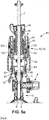
[Fig. 1 ] montre un dispositif de perçage selon un mode de réalisation de l'invention, seul, c'est-à-dire non relié à un collier de dérivation d'une canalisation, dans la position de repos du mécanisme de manœuvre c'est-à-dire les moyens élastiques alors non en charge. -
Fig. 2
[Fig. 2 ] est une vue de coupe du dispositif selon lafigure 1 dans la position de repos du mécanisme de manœuvre, selon un plan passant par l'axe de l'arbre portant l'outil de coupe, et par les axes de rotation de deux leviers de commande du mécanisme de manœuvre, illustrant l'état non compressé du ressort à spires des moyens élastiques, la troisième partie formant un siège pour l'extrémité supérieure du ressort étant dans une position haute, éloignée de la partie de connexion du corps, autorisant au ressort de prendre une position déployée (non compressée). -
Fig. 3
[Fig. 3 ] est une vue du dispositif selon lafigure 1 , dans la position de repos du mécanisme de manœuvre selon un plan passant par la came et le suiveur de came associé à un des deux levier de commande du mécanisme de manœuvre, le suiveur de came étant contraint par le chemin de la came à prendre un rayon éloigné du centre de pivot du levier, contraignant la troisième partie par rapport au corps dans ladite position éloignée de la partie de connexion (ressort non compressé). -
Fig. 4
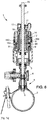
[Fig. 4 ] est une vue du dispositif de perçage dont la partie de connexion du corps est fixée au robinet du collier de dérivation fixé par sa bride à la canalisation, l'arbre ayant été préalablement fixé à la seconde partie, dans la position de repos du mécanisme de manœuvre, de sorte que l'outil soit en butée contre la paroi de la canalisation, le mécanisme de manœuvre étant basculé dans la position de travail assurant la mise en charge des moyens élastiques. -
Fig. 5
[Fig. 5 ] est une vue de coupe du dispositif dans la position de travail selon lafigure 4 , illustrant plus particulièrement la position relative du suiveur de came (galet) dans le chemin de la came, contraignant le galet à prendre un rayon rapproché du centre de pivot du levier, contraignant la troisième partie par rapport au corps dans la position rapprochée par rapport à la partie de connexion afin de comprimer le ressort à spires. -
Fig. 5a
[Fig. 5a ] est une vue de coupe du dispositif de lafigure 4 selon un plan passant par l'axe de l'arbre et par l'axe passant par les axes de rotation des deux leviers de commande, illustrant plus particulièrement le ressort à spires des moyens élastiques en charge, à l'état compressé, ladite première partie alors bloquée en coulissement par ledit arbre alors fixé à la seconde partie de l'outil de coupe alors en butée contre la canalisation. -
Fig. 6
[Fig. 6 ] est une vue de coupe du dispositif selon un plan passant par l'axe de l'arbre et par l'axe passant par les axes de pivots de deux leviers de commande, lors d'une étape successive à celle de lafigure 5a , c'est-à-dire en fin de perçage, l'outil de coupe ayant traversé et percé la paroi de la canalisation, la course de déplacement de l'outil de coupe étant limitée par la mise en butée de la première partie contre le corps, - .
Fig. 7a
[Fig. 7a ] est une vue de détail du mécanisme de manœuvre alors en position de repos selon lafigure 2 , le ressort à spires (ressort en compression) des moyens élastiques étant non en charge (à l'état déployé) lorsque la troisième partie formant un siège pour l'extrémité supérieure du ressort est en position haute dans la position éloignée de la partie de connexion, et dans une position où la première partie n'est pas en butée contre le corps, bloqué par l'arbre et l'outil en butée contre la canalisation, la première partie étant susceptible de se déplacer vers la canalisation selon une course limitée sous la contrainte des moyens élastiques pour que l'outil de coupe traverse la paroi lorsque l'outil est mis en rotation. -
Fig. 7b
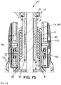
[Fig. 7b ] est une vue de détail du mécanisme de manœuvre selon lafigure 5 , successive à l'étape de lafigure 7a lors de la mise en œuvre du procédé de perçage, lorsque le mécanisme de manœuvre est passé dans la position de travail, le ressort à spires (ressort en compression) des moyens élastiques étant mis en charge (à l'état compressé) lorsque la troisième partie formant un siège pour l'extrémité supérieure du ressort est passé en position basse dans la position rapprochée de la partie de connexion, la première partie alors bloquée en coulissement par ledit arbre alors fixé à la seconde partie de l'outil de coupe alors en butée contre la canalisation. -
Fig. 7c
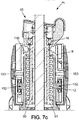
[Fig. 7c ] est une vue successive à lafigure 7b lors de la mise en œuvre du procédé de perçage, et correspondant à une vue de détail de lafigure 6 , le mécanisme de manœuvre dans sa position de travail, le ressort des moyens élastiques ayant été déployé en déplaçant la première partie et conjointement l'arbre et l'outil de coupe pour percer la canalisation, la course de la première partie étant limitée par la mise en butée de la première partie contre le corps.
-
Fig. 1
[Fig. 1 ] shows a drilling device according to one embodiment of the invention, alone, that is to say not connected to a bypass collar of a pipe, in the rest position of the operating mechanism, that is to say that is to say the elastic means then not under load. -
Fig. 2
[Fig. 2 ] is a sectional view of the device according tofigure 1 in the rest position of the operating mechanism, along a plane passing through the axis of the shaft carrying the cutting tool, and through the axes of rotation of two control levers of the operating mechanism, illustrating the non-state of the coil spring of the elastic means, the third part forming a seat for the upper end of the spring being in a high position, remote from the part of connection of the body, allowing the spring to assume a deployed (uncompressed) position. -
Fig. 3
[Fig. 3 ] is a view of the device according tofigure 1 , in the rest position of the operating mechanism according to a plane passing through the cam and the cam follower associated with one of the two operating lever control mechanism, the cam follower being forced by the path of the cam to take a radius away from the pivot center of the lever, constraining the third part relative to the body in said position remote from the connection part (uncompressed spring). -
Fig. 4
[Fig. 4 ] is a view of the drilling device of which the connection part of the body is fixed to the tap of the bypass collar fixed by its flange to the pipe, the shaft having been previously fixed to the second part, in the rest position of the mechanism operating, so that the tool is in abutment against the wall of the pipe, the operating mechanism being tilted into the working position ensuring the loading of the elastic means. -
Fig. 5
[Fig. 5 ] is a sectional view of the device in the working position according tofigure 4 , illustrating more particularly the relative position of the cam follower (roller) in the path of the cam, forcing the roller to take a radius close to the center of the pivot of the lever, forcing the third part with respect to the body in the position close to to the connection part in order to compress the coil spring. -
Fig. 5a
[Fig. 5a ] is a sectional view of the device of thefigure 4 along a plane passing through the axis of the shaft and through the axis passing through the axes of rotation of the two control levers, more particularly illustrating the coil spring of the elastic means under load, in the compressed state, said first then gone locked in sliding by said shaft then fixed to the second part of the cutting tool then in abutment against the pipe. -
Fig. 6
[Fig. 6 ] is a sectional view of the device along a plane passing through the axis of the shaft and through the axis passing through the pivot axes of two control levers, during a step successive to that of thefigure 5a , that is to say at the end of drilling, the cutting tool having passed through and pierced the wall of the pipe, the travel of the cutting tool being limited by the abutment of the first part against the body, - .
Fig. 7a
[Fig. 7a ] is a detailed view of the operating mechanism then in the rest position according to thefigure 2 , the coil spring (compression spring) of the elastic means being unloaded (in the deployed state) when the third part forming a seat for the upper end of the spring is in the high position in the position remote from the part of connection, and in a position where the first part is not in abutment against the body, blocked by the shaft and the tool in abutment against the pipe, the first part being capable of moving towards the pipe with a limited stroke under the constraint of the elastic means so that the cutting tool passes through the wall when the tool is rotated. -
Fig. 7b
[Fig. 7b ] is a detailed view of the operating mechanism according tofigure 5 , successive to the stage offigure 7a during the implementation of the drilling method, when the operating mechanism has passed into the working position, the coil spring (compression spring) of the elastic means being loaded (in the compressed state) when the third part forming a seat for the upper end of the spring is passed in the low position in the position close to the connection part, the first part then locked in sliding by said shaft then fixed to the second part of the cutting tool then in stop against the pipe. -
Fig. 7c
[Fig. 7c ] is a successive view tofigure 7b during the implementation of the drilling method, and corresponding to a detail view of thefigure 6 , the operating mechanism in its working position, the spring of the elastic means having been deployed by moving the first part and jointly the shaft and the cutting tool to pierce the pipe, the stroke of the first part being limited by the abutment of the first part against the body.
Aussi, l'invention est relative à un dispositif de perçage 1 convenant pour le perçage d'une canalisation 2 en charge (ou non), comprenant une partie de connexion 3 configurée pour être fixée de manière amovible sur un robinet 4 d'un collier de dérivation 5, ainsi qu'un outil de coupe 6 déplaçable par rapport à ladite partie de connexion 3, configuré pour traverser ledit robinet 4 pour permettre le perçage de la canalisation 2.Also, the invention relates to a
Le dispositif selon l'invention comprend:
un arbre 7 couplé à l'une de ses extrémités à l'outil decoupe 6 ; l'autre extrémité de l'arbre, dite extrémité distale 70 étant destinée à être reliée à des moyens moteurs pour l'entraînement en rotation de l'outil decoupe 6,un corps 8 rigidement solidaire de la partie de connexion 3,- une première partie, mobile en coulissement par
rapport audit corps 8 selon une course limitée, grâce à des moyens de guidage entre ladite première partie 9 et leditcorps 8, dirigés suivant une direction parallèle à l'arbre 7, - une seconde partie 10, mobile en rotation par rapport à ladite première partie 9 grâce à des moyens de guidage en rotation entre ladite seconde partie et ladite première partie, d'axe confondu à celui de l'arbre, ladite seconde partie 10 étant solidaire en coulissement avec la première partie 9, ladite seconde partie 10 comprenant un moyen de
fixation 11 amovible dudit arbre, - des moyens élastiques 12 configurés pour contraindre ladite première partie 9, mobile, par
rapport au corps 8 dans le sens de perçage - des moyens 13 de mise en charge desdits moyens élastiques.
- a
shaft 7 coupled at one of its ends to thecutting tool 6; the other end of the shaft, called thedistal end 70, being intended to be connected to motor means for driving thecutting tool 6 in rotation, - a
body 8 rigidly secured to theconnection part 3, - a first part, movable in sliding relative to said
body 8 according to a limited stroke, by means of guide means between saidfirst part 9 and saidbody 8, directed in a direction parallel to theshaft 7, - a
second part 10, movable in rotation with respect to saidfirst part 9 thanks to means for guiding in rotation between said second part and said first part, of axis coincident with that of the shaft, saidsecond part 10 being integral in sliding with thefirst part 9, saidsecond part 10 comprising a removable fixing means 11 of said shaft, - elastic means 12 configured to constrain said
first part 9, movable, relative to thebody 8 in the drilling direction - means 13 for loading said elastic means.
Un tel dispositif est configuré de sorte à permettre un perçage pendant lequel l'effort de perçage (effort de poussée) et l'avance de l'outil de coupe 6 sont assurés uniquement par les moyens élastiques 12. De manière avantageuse, et à l'instar du dispositif selon
La course de l'outil de coupe est limitée de sorte à éviter que l'outil de coupe 6 ne viennent endommager la paroi de la canalisation opposée à celle qui vient d'être traversée par l'outil de coupe 6, en fin de perçage. Par exemple, en fin de course la première partie 9 vient en en contact avec une butée formée sur le corps 8.The stroke of the cutting tool is limited so as to prevent the
En utilisation les moyens moteurs (non illustrés) peuvent comprendre une perceuse ou visseuse notamment du commerce. Les moyens moteurs sont couplés à l'extrémité distale 70 de l'arbre 7 qui peut être de section polygonale, tel que par exemple de section carrée ou hexagonale. En utilisation, les moyens moteurs sont bloqués en rotation, soit par la main de l'utilisateur lui-même, soit par un support mécanique (non illustré) configuré pour accompagner le déplacement de l'arbre. Dans le cas où l'utilisateur bloque la rotation des moyens moteurs, il n'exerce aucun effort dans la direction de l'arbre, suivant le sens de poussée ou dans le sens opposé.In use, the motor means (not illustrated) can comprise a drill or screwdriver, in particular a commercial one. The motor means are coupled to the
De manière notable, les moyens 13 de mise en charge comprennent :
- une troisième partie 14, mobile en coulissement par
rapport au corps 8 et par rapport à la première partie 9, lesdits moyens élastiques 12 étant prévus pour être compressés entre un appui formé sur la troisième partie 14, et un appui formé sur la première partie 9 de sorte que lesdits moyens élastiques 12 sont configurés pour être compressés par déplacement de la troisième partie 14 parrapport au corps 8, tandis que la première partie 9 reste fixe parrapport audit corps 8, un mécanisme 15 de manœuvre entre le corps 8 et la troisième partie 14 configuré pour assurer le déplacement de la troisième partie 14 sur le corps 8 suivant le sens de perçage ; ledit mécanisme de manœuvre 15 étant configuré pour prendre deux positions, y compris une position de repos Pr dans laquelle la troisième partie 14 est dans une position éloignée de la partie de connexion 3, et une position de travail Pt dans laquelle la troisième partie 14 est dans une position rapprochée de la partie deconnexion 3.
- a
third part 14, movable in sliding relative to thebody 8 and relative to thefirst part 9, said elastic means 12 being provided to be compressed between a support formed on thethird part 14, and a support formed on thefirst part 9 so that said elastic means 12 are configured to be compressed by displacement of thethird part 14 relative to thebody 8, while thefirst part 9 remains fixed relative to saidbody 8, - a
maneuvering mechanism 15 between thebody 8 and thethird part 14 configured to ensure the movement of thethird part 14 on thebody 8 in the direction of drilling; saidoperating mechanism 15 being configured to take two positions, including a rest position Pr in which thethird part 14 is in a position remote from theconnection part 3, and a working position Pt in which thethird part 14 is in a position close to theconnection part 3.
Selon l'invention, le mécanisme de manœuvre 15 est ainsi configuré pour assurer la compression des moyens élastiques 12 par le passage de la position de repos Pr vers la position de travail Pt lorsque la première partie 9 est bloquée en coulissement par ledit arbre 7 alors fixé à la seconde partie 10, l'outil de coupe 6 alors en butée contre la canalisation 2, et comme illustrés aux
Un tel dispositif de perçage permet ainsi la mise en œuvre d'un procédé de perçage, la partie de connexion 3 du dispositif de perçage étant préalablement alors solidarisée au robinet 4 du collier de dérivation 5, ledit procédé comprenant les étapes suivante
- mise en place de l'arbre 7 jusqu'à la mise en butée 6 de l'outil de coupe sur la
canalisation 2 et fixation de l'arbre à la seconde partie 10 du dispositif de perçage via le moyen 11 de fixation amovible, - passage du mécanisme de manœuvre 15 de la première position de repos Pr dans laquelle la troisième partie 14 est dans une position éloignée de la partie de connexion 3 vers la position de travail Pt dans laquelle la troisième partie 14 est dans une position rapprochée de la partie de connexion 3 assurant ainsi la compression des moyens élastiques 12, ladite première partie 9 étant bloquée en coulissement par ledit arbre 7 alors fixé à la seconde partie 10, l'outil de
coupe 6 en butée contre la canalisation 2, - couplage de l'extrémité distale de l'arbre 7 à des moyens moteurs
- perçage par la mise en rotation conjointe de l'arbre 7 et de l'outil de
coupe 6, de telle façon que l'effort de perçage et l'avance de l'outil decoupe 6 sont assurés uniquement par lesdits moyens élastiques 12.
- positioning of the
shaft 7 up to theabutment 6 of the cutting tool on thepipe 2 and fixing of the shaft to thesecond part 10 of the drilling device via the removable fixing means 11, - passage of the
operating mechanism 15 from the first rest position Pr in which thethird part 14 is in a position remote from theconnection part 3 to the working position Pt in which thethird part 14 is in a position close to thepart connection 3 thus ensuring the compression of the elastic means 12, saidfirst part 9 being blocked in sliding by saidshaft 7 then fixed to thesecond part 10, thecutting tool 6 in abutment against thepipe 2, - coupling of the distal end of the
shaft 7 to motor means - drilling by the joint rotation of the
shaft 7 and thecutting tool 6, so that the drilling force and the advance of thecutting tool 6 are provided only by saidelastic means 12.
Selon le procédé selon invention, la fixation de l'arbre 7 portant l'outil de coupe 6 se fait nécessairement avant la mise en compression des moyens élastique 12. A défaut la première partie coulisserait librement dans le corps lorsque le mécanisme est passé en position de travail et les moyens élastiques ne seraient alors pas compressés lors de cette étape. On interdit ainsi l'armement à vide du dispositif de perçage selon l'invention Par comparaison, et dans le dispositif de perçage selon
La structure du dispositif de perçage selon l'invention est ainsi avantageuse par rapport à celui du document
Le corps 8 est de préférence un corps creux, tubulaire traversé suivant son axe longitudinal par l'arbre 7 qui ressort du dispositif de perçage à son extrémité distale 70 pour permettre son couplage aux moyens moteurs, et ressort à son extrémité proximale portant l'outil de coupe 6, de l'autre côté. Ce corps 8 est équipé de la partie de connexion 3 à l'une de ces extrémités, dite extrémité proximale 81, et présente à son autre extrémité une cavité 82 à l'intérieur de laquelle la première partie 9 est configurée pour coulisser. La cavité peut être cylindrique, la première partie présentant un élément coulissant tel qu'un piston coulissant dans cette cavité 82.The
La partie de connexion 3 peut comprendre une partie filetée 30, notamment un taraudage destinée à être fixée par vissage sur une partie filetée du robinet du collier de dérivation. La partie de connexion 3 peut encore comprendre un adaptateur 31 amovible par rapport au corps portant la partie filetée 30. La partie de fixation 83 entre l'adaptateur 31 et le corps 8 peut comprendre un système d'agrafe, voire encore un taraudage du corps 8 à l'intérieur duquel est vissé l'adaptateur 31 présentant alors une seconde partie filetée 32.The
L'adaptateur 31 est changé en fonction des caractéristiques de la partie filetée du robinet. Le dispositif de perçage peut comprendre un jeu de plusieurs adaptateurs 31, afin de pouvoir être fixé à différents robinets de collier de dérivation.The adapter 31 is changed depending on the characteristics of the threaded part of the tap. The piercing device may include a set of multiple adapters 31, so that it can be attached to different bypass collar taps.
La première partie 9 peut comprendre un tube 90, notamment cylindrique, coaxial à l'arbre 7 et traversé par ledit arbre 7. Les moyens élastiques 12 peuvent être un ressort à spires monté autour du tube 90. Un épaulement 91 en saillie forme un siège pour une extrémité du ressort à spires, l'autre extrémité du ressort à spires étant en appui sur un siège 140 formé sur la troisième partie 14.The
De manière générale, il est à noter que les moyens élastiques 12 peuvent éventuellement prendre d'autres formes telles qu'un ressort pneumatique.In general, it should be noted that the elastic means 12 can optionally take other forms such as a pneumatic spring.
Le mécanisme 15 de manœuvre peut comprendre un levier de commande150, 150', articulé en pivot sur la troisième partie 14, ainsi qu'un couple came 151 et suiveur de came 152 répartis entre le corps 8 et le levier 150 ; 150'. Le suiveur de came 152 peut être solidaire du corps 8 et la came 151 solidaire de la base du levier de commande. L'inversion des positions de la came et du suiveur est possible, mais non illustrée.The
Ledit mécanisme de manœuvre est configuré pour prendre ladite position de repos Pr correspondant à une première position relative de la came 151 par rapport au suiveur de came 152, et ladite position de travail Pt est obtenue par pivotement du levier de commande 150 ; 150', correspondant à une deuxième position relative de la came 151 par rapport au suiveur de came 152. Le pivotement du levier 150, 150' assurant le changement entre les deux positions Pr et Pt peut être d'un angle compris entre 45° et 135 °, tel que 90° La came 151 comprend un chemin de came formé sur une partie de base du levier de commande 150 ; 150', le chemin étant de rayon variable par rapport à l'axe de rotation 153 (ou de pivot) du levier de commande de rayon lors de la rotation du levier autour de l'axe de rotation 153.Said maneuver mechanism is configured to take said rest position Pr corresponding to a first relative position of the
Lorsque la came 151 est solidaire du levier et le suiveur de came 152 solidaire de la troisième partie 14, le rayon du chemin de came 151 peut être sensiblement décroissant pour le suiveur de came 152 lorsque ce dernier se déplace dans le chemin de came entre la position de repos Pr et la position de travail Pt.When the
Autrement dit :
- dans la position de repos Pr telle qu'illustrée à la
figure 3 , on remarque que le suiveur de came 152 (en l'espèce un galet) est dans la portion du chemin de la came 151 de rayon le plus éloigné de l'axe derotation 153. - dans la position de travail Pt, telle qu'illustrée à la
figure 5 , on remarque que le suiveur de came 152 (en l'espèce un galet) est dans la portion du chemin de la came 151 de rayon proche de l'axe derotation 153.
- in the rest position Pr as shown in
figure 3 , we note that the cam follower 152 (in this case a roller) is in the portion of the path of thecam 151 with the radius furthest from the axis ofrotation 153. - in the working position Pt, as shown in
figure 5 , we note that the cam follower 152 (in this case a roller) is in the portion of the path of thecam 151 with a radius close to the axis ofrotation 153.
La différence des rayons entre la position du suiveur de came 152 respectivement dans la position éloignée et dans la position proche de l'axe de rotation correspond à une course Cc de la troisième partie 14 sur le corps 8, imposée par le mécanisme de manœuvre 15. Cette course de la troisième partie 14 sur le corps assure la compression des moyens élastiques 12 d'un même déplacement. Cette course Cc est visible à la
A la
Le chemin de la came 151 peut présenter deux butées en fin de course pour ledit suiveur de came 152 ; avec une première butée 154 pour le suiveur de came 152 dans la position de repos Pr du mécanisme de manœuvre et une deuxième butée 155 pour le suiveur de came dans la position de travail Pt du mécanisme de manœuvre.The path of the
Selon un mode de réalisation, le chemin de came est de rayon décroissant par rapport à l'axe de rotation 153 du levier de commande pour le suiveur de came 152, immédiatement avant la deuxième fin de course 155 puis de rayon brutalement croissant lorsque ledit suiveur de came 152 arrive dans ladite deuxième fin de course 155. La deuxième fin de course 155 constitue alors une position stable du suiveur de came 152 dans le chemin de came dans ladite position de travail Pt du mécanisme de manœuvre 15. Autrement dit, la stabilité de la position de travail Pt assurant la compression des moyens élastiques est assurée par la trajectoire particulière de la came 151 (le chemin de came) et sa coopération avec la suiveur de came 152.According to one embodiment, the cam track has a decreasing radius with respect to the axis of
De manière générale, le suiveur de came 152 peut être un galet articulé en pivot notamment sur le corps 8 suivant un axe de pivot sensiblement perpendiculaire à l'arbre 7.In general, the
Selon un mode de réalisation illustré aux figures; le mécanisme de manœuvre 15 comprend deux dit leviers de manœuvre 150 ; 150', chacun étant associé à un couple came 151 et suiveur de came 152 répartis entre le corps 8 et le levier de commande, lesdits deux couples de came 151 et suiveur de came 152 étant répartis de part et d'autre de l'arbre 7.According to one embodiment illustrated in the figures; the
Un tel mode de réalisation est illustré aux figures à titre d'exemple non limitatif. Les axes de rotation 153 des deux leviers de commande 150 ; 150' sont confondus, les chemins de came des deux couples présentant une trajectoire en miroir afin d'imposer un même déplacement à la troisième partie 14 lors de la mise en rotation synchronisée des leviers de commande 150, 150' en des sens contraires.Such an embodiment is illustrated in the figures by way of non-limiting example. The axes of
Il est encore à noter que chaque levier 150 (resp 150 ') de commande peut être à branches double, avec une première branche présentant la came 151 au niveau de la base du levier articulé en rotation sur la troisième partie 14, d'un côté de l'arbre 7, une deuxième branche (parallèle) étant articulée à sa base de l'autre côté suivant le même axe de rotation 153 de la came de l'autre levier 150' (resp 150), et sans être liée à la came de ce côté. Les deux branches de levier à branches double sont solidaires l'une à l'autre par leur extrémité distale via une poignée 156.It should also be noted that each control lever 150 (resp 150 ') can have double branches, with a first branch having the
Selon un mode de réalisation avantageux illustré aux figures à titre d'exemple non limitatif, on constate que la came 151 et le suiveur de came 152 du mécanisme de manœuvre 15 sont logés dans un boitier. Ce boitier est avantageusement configuré afin d'interdire les risques de pincement entre la came 151 et le suiveur de came 152.According to an advantageous embodiment illustrated in the figures by way of non-limiting example, it can be seen that the
De manière générale, la troisième partie 14 peut former un boitier recevant partiellement dans son intérieur le corps 8 au moins partiellement à l'extrémité opposée de la partie de connexion 3, et la première partie 9 à fonction de coulisseau. On constate ainsi que la troisième partie 14 comporte une portée de guidage 141, interne, configurée pour coulisser sur une portée de guidage externe 80 du corps 8.In general, the
Les moyens de guidage en rotation entre ladite seconde partie 10 et ladite première partie 9, d'axe de rotation confondu à celui de l'arbre peuvent être un palier ou un roulement 16, et comme visible à la
Le moyen 11 de fixation amovible de l'arbre comprend un système de fixation par arc-boutement comprenant une tôle 110 pourvue d'une ouverture de passage 111 pour l'arbre, et un moyen résilient 112 configuré pour la mise en biais de l'ouverture, et ainsi l'obtention du blocage par les frottements entre les bords de l'ouverture et ledit arbre. Ce système de fixation assure automatiquement l'arrêt axial de l'arbre 7 par la tôle grâce à la mise en biais de la tôle et l'arc-boutement ainsi crée entre l'arbre et cette tôle. Pour retirer l'arbre, il suffit de presser manuellement la tôle sur une partie d'appui 114 de la tôle à l'encontre de la force de rappel du moyen résilient 112 qui pivote autour d'un point de pivot 113, et jusqu'à une position de la tôle annihilant l'arc-boutementThe means 11 for removable fixing of the shaft comprises a fixing system by bracing comprising a
L'arrêt axial engendré par ce dispositif est de préférence non symétrique, un tel système de fixation par arc-boutement assurant :
- un arrêt axial fort, afin d'éviter tout glissement de l'arbre dans la tôle, selon le sens opposé au sens de perçage, afin de permettre la compression des moyens élastiques, puis la transmission de l'effort de rappel des moyens élastiques lorsque l'outil de coupe appuie contre la canalisation,
- un arrêt axial plus faible dans le sens opposé, à savoir suivant le sens de perçage, l'arbre pouvant éventuellement être déplacé vers la canalisation, en glissant au travers de la tôle (du système de fixation par arc-boutement) grâce à un léger effort de l'opérateur sur l'arbre, par exemple pour plaquer l'outil de coupe contre la canalisation. Les frottements entre l'arbre et la tôle sont toutefois de préférence suffisant afin de retenir l'arbre et l'outil de coupe en fin perçage, en s'opposant à la gravité.
- a strong axial stop, in order to prevent any sliding of the shaft in the sheet, in the direction opposite to the drilling direction, in order to allow the compression of the elastic means, then the transmission of the return force of the elastic means when the cutting tool presses against the pipe,
- a weaker axial stop in the opposite direction, namely according to the drilling direction, the shaft possibly being able to be moved towards the pipe, in sliding through the sheet metal (of the overhanging fixing system) thanks to a slight effort by the operator on the shaft, for example to press the cutting tool against the pipe. The friction between the shaft and the sheet is however preferably sufficient in order to retain the shaft and the cutting tool at the end of the drilling, by opposing gravity.
L'outil de coupe 6 peut être une pièce cylindrique, tubulaire, présentant une arrête de coupe 60, de préférence discontinue, avec la présence d'encoches 61 de préférence réparties régulièrement sur la circonférence de l'arête. L'arête peut être recouverte de poudre abrasive, telle que la poudre de diamant. La paroi de la pièce cylindre peut présenter une ouverture destinée à permettre l'écoulement d'un liquide. Cette ouverture est de préférence dimensionnée suffisamment large afin de permettre la récupération de la partie de la canalisation, qui vient d'être coupée, et d'afin d'éviter que cette partie tombe dans la canalisation.The
L'invention peut trouver à s'appliquer notamment dans le domaine de l'adduction d'eau lorsqu' il est nécessaire de créer de nouveau raccordement à une canalisation.The invention can be applied in particular in the field of water supply when it is necessary to create a new connection to a pipe.
- 1 : Dispositif de perçage1: Drilling device
- 2. Canalisation2. Pipe
- 3. Partie de connexion,3. Connection part,
- 30. Partie filetée (fixation au robinet)30. Threaded part (fixing to the valve)
- 31. Adaptateur31. Adapter
- 32. Seconde partie filetée (fixation au adaptateur au corps)32. Second threaded part (attachment to the adapter to the body)
- 4. Robinet4. Tap
- 5. Collier de dérivation,5. Bypass collar,
- 6 Outil de coupe6 Cutting tool
- 60. Arête de coupe60. Cutting edge
- 61. Encoches61. Notches
- 7. Arbre7. Tree
- 8.Corps8.Body
- 80. Portée de guidage externe80. External guidance scope
- 81. Extrémité proximale81. Proximal end
- 82. Cavité82. Cavity
- 83. partie de fixation (de l'adaptateur au corps)83. fixing part (from adapter to body)
- 9. Première partie9. Part one
- 90. Tube90. Tube
- 91. Epaulement91. Shoulder
- 10. Seconde partie,10. Second part,
- 11. Moyen de fixation,11. Fixing means,
- 110. Tôle ;110. Sheet metal;
- 111. Ouverture de passage111. Passage opening
- 112. Moyen résilient,112. Resilient medium,
- 113. Point de pivot113. Pivot point
- 114. Partie d'appui114. Support part
- 12. Moyens élastiques12. Elastic means
- 13. Moyens de mise en charge desdits moyens élastique13. Means for loading said elastic means
- 14. Troisième partie,14. Part Three,
- 140. Siège140. Headquarters
- 141. Portée de guidage interne141. Internal guidance scope
- 15. Mécanisme de manœuvre,15. Operating mechanism,
- 150, 150'. Levier de commande,150, 150 '. Control lever,
- 151, 152. Came et suiveur de came,151, 152. Cam and cam follower,
- 153. Axe rotation du levier de commande153. Control lever rotation axis
- 154, 155. Première butée de fin de course et deuxième butée de fin de course154, 155. First end stop and second end stop
-
156. Poignée (du levier de commande 150 ou 150' à double branches)156. Handle (from the
control lever 150 or 150 'with double arms) - Cc Course de la troisième partie imposé par le mécanisme de manœuvre.Cc Course of the third part imposed by the maneuver mechanism.
- Co. Course limitée de la première partie dans le corpsCo. Limited stroke of the first part in the body
- Pt. Position de travail,Pt. Working position,
- Pr. Position de reposPr. Rest position
Claims (12)
- A drilling device (1) suitable for drilling a pipe (2) under load, comprising a connection part (3) configured to be removably fixed to a tap (4) of a bypass collar (5), as well as a cutting tool (6) that can be displaced relative to said connection part (3), configured to pass through said tap (4) to allow drilling the pipe (2), said drilling device (1) comprising:- a shaft (7) coupled at one of its ends to the cutting tool; the other end of the shaft being intended to be connected to motor means for rotating the cutting tool,- a body (8) rigidly integral to the connection part (3),- a first part (9), slidably movable relative to said body (8) along a limited travel, thanks to guide means between said first part and said body, directed in a direction parallel to the shaft,- a second part (10), rotatably movable relative to said first part thanks to rotational guide means between said second part and said first part, of axis coincident with that of the shaft, said second part comprising a means (11) for removably fixing said shaft,- elastic means (12) configured to constrain said first movable part relative to the body in the drilling direction,- means (13) for loading said elastic meanssaid device being configured so as to allow a drilling during which the drilling force and the forward movement of the cutting tool are provided only by the elastic means, characterised in that the loading means (13) comprise:- a third part (14), slidably movable relative to the body (8) and relative to the first part (9), said elastic means (12) being provided to be compressed between a bearing formed on the third part (14), and a bearing formed on the first part (9) so that said elastic means are configured to be compressed by displacement of the third part relative to the body, while the first part remains fixed relative to said body,- an operating mechanism (15) between the body (8) and the third part (14) configured to ensure the displacement of the third part (14) on the body (8) in the direction of drilling said operating mechanism (15) being configured to assume two positions, including a rest position (Pr) wherein the third part (14) is in a position remote from the connection part (3), and a working position (Pt) wherein the third part (14) is in a position close to the connection part (3), said operating mechanism (15) being configured to ensure the compression of the elastic means (12) by switching from the rest position (Pr) to the working position (Pt) when the first part (9) is slidably blocked by said shaft (7) then fixed to the second part (10), the cutting tool (6) then abutting against the pipe (2).
- The device according to claim 1, wherein the first part (9) comprises a tube (90), coaxial with the shaft and traversed by said shaft (7), and wherein the elastic means (12) comprise a spiral spring mounted around the tube (90), a projecting shoulder (91) forming a seat for one end of the spiral spring, the other end of the spiral spring being bearing on a seat (140) formed on the third part (14).
- The device according to claim 1 or 2, wherein the operating mechanism (15) comprises a control lever (150, 150') pivotally articulated on the third part (14), as well as a cam (151) and cam follower (152) pair distributed between the body (8) and the lever (150; 150'), the cam follower (152) being integral with the body (8) and the cam (151) integral with the base of the control lever, said operating mechanism being configured to assume said rest position (Pr) corresponding to a first relative position of the cam (151) relative to the cam follower (152), and said working position (Pt), obtained by pivoting the control lever (150; 150'), and corresponding to a second relative position of the cam (151) relative to the cam follower (152), and wherein the cam (151) comprises a cam track formed on a base part of the control lever (150; 150'), the path being of variable radius relative to the axis of rotation (153) of the control lever of substantially decreasing radius for the cam follower (152) between the rest position (Pr) and the working position (Pt) in order to force the third part (14) from the position remote from the connection part (3) towards the position close to the connection part (3).
- The device according to claim 3 wherein the cam track has two end-of-travel stops for said cam follower (152); with a first stop (154) for the cam follower in the rest position (Pr) of the operating mechanism and a second stop (155) for the cam follower in the working position (Pt) of the operating mechanism.
- The device according to claim 4 wherein the cam track has a decreasing radius relative to the axis of rotation (153) for the cam follower (152), immediately before the second end of travel (155) then has a suddenly increasing radius when said cam follower arrives in said second end of travel (155), in order to constitute a stable position of the cam follower (152) in the cam track in said working position (Pt) of the operating mechanism (15).
- The device according to claim 3, 4 or 5 wherein the cam (151) and the cam follower (152) of the operating mechanism (15) are housed in a casing (155) configured to prevent the risk of pinching between the cam (151) and the cam follower (152).
- The device according to one of claims 3 to 6, wherein the cam follower (152) is a roller pivotally articulated on the body (8) along a pivot axis substantially perpendicular to the shaft (7).
- The device according to any one of claims 3 to 7, wherein the operating mechanism (15) comprises two said operating levers (150; 150'), each being associated with a cam (151) and a cam follower (152) pair distributed between the body (8) and the control lever, said two cam (151) and cam follower (152) pairs being distributed on either side of the shaft (7).
- The device according to any one of claims 1 to 8, wherein the third part (14) forms a casing partially receiving in its interior:- the body (8) at least partially at the opposite end of the connection part (3),- the first part (9),and wherein the third part (14) includes an internal guide surface (141) configured to slide on an external surface (80) of the body (8).
- The device according to one of claims 1 to 9, wherein the cutting tool (6) is a cylindrical, tubular part having a cutting edge (60), which is discontinuous, with notches (61), the edge present being covered with diamond powder, and the wall of the cylindrical part having an opening intended to allow the flow of a liquid.
- The device according to one of claims 1 to 10, wherein the means (11) for removably fixing the shaft comprises a system for fixing by bracing comprising a sheet (110) provided with a passage opening (111) for the shaft, and a resilient means (112) configured to bias the opening in order to provide frictional blocking between the edges of the opening and said shaft.
- A method for drilling a pipe comprising a bypass collar provided with a tap, implemented by a drilling device (1) according to any one of claims 1 to 11 the connection part of which is integral with the tap (4) of the bypass collar (5), said method comprising the following steps:- positioning the shaft (7) until abutting the cutting tool (6) on the pipe (2) and fixing the shaft to the second part of the drilling device via the removable fixing means (11),- switching the operating mechanism (15) from the first rest position (Pr) wherein the third part (14) is in a position remote from the connection part (3) to the working position (Pt) wherein the third part (14) is in a position close to the connection part (3) thus ensuring the compression of the elastic means (12), said first part being slidably blocked by said shaft (7) then fixed to the second part (10), the cutting tool (6) being abutted against the pipe (2),- coupling the distal end of the shaft (7) to motor means,- drilling by rotating the shaft and the cutting tool, so that the drilling force and the forward movement of the cutting tool (6) are provided only by said elastic means (12).
Applications Claiming Priority (1)
| Application Number | Priority Date | Filing Date | Title |
|---|---|---|---|
| FR1900509A FR3091826B1 (en) | 2019-01-21 | 2019-01-21 | Device for drilling a pipe |
Publications (2)
| Publication Number | Publication Date |
|---|---|
| EP3682992A1 EP3682992A1 (en) | 2020-07-22 |
| EP3682992B1 true EP3682992B1 (en) | 2021-08-18 |
Family
ID=66776552
Family Applications (1)
| Application Number | Title | Priority Date | Filing Date |
|---|---|---|---|
| EP20152517.7A Active EP3682992B1 (en) | 2019-01-21 | 2020-01-17 | Drilling device for a pipe |
Country Status (3)
| Country | Link |
|---|---|
| EP (1) | EP3682992B1 (en) |
| ES (1) | ES2896707T3 (en) |
| FR (1) | FR3091826B1 (en) |
Family Cites Families (4)
| Publication number | Priority date | Publication date | Assignee | Title |
|---|---|---|---|---|
| FR2772874B1 (en) | 1997-12-19 | 2000-01-28 | Saint Germain Et Straub Ets | DEVICE AND METHOD FOR MOUNTING A BYPASS ON A PIPE AND CORRESPONDING TAP |
| IL124919A (en) * | 1998-06-15 | 2001-01-28 | Ppc Ltd | Pipe tapping |
| FR2984784B1 (en) | 2011-12-22 | 2014-09-26 | Commissariat Energie Atomique | METHOD FOR ASSEMBLING SIC - BASED MATERIAL PARTS BY NON - REACTIVE BRAZING USING THE OXIDIZING ATMOSPHERE PROCEDE. BRAZING COMPOSITIONS, AND JOINT AND ASSEMBLY OBTAINED BY THIS PROCESS. |
| FR2984780B1 (en) | 2011-12-27 | 2014-01-10 | Saint Germain Et Straub Ets | DEVICE FOR DRILLING A PIPING |
-
2019
- 2019-01-21 FR FR1900509A patent/FR3091826B1/en active Active
-
2020
- 2020-01-17 EP EP20152517.7A patent/EP3682992B1/en active Active
- 2020-01-17 ES ES20152517T patent/ES2896707T3/en active Active
Also Published As
| Publication number | Publication date |
|---|---|
| FR3091826A1 (en) | 2020-07-24 |
| EP3682992A1 (en) | 2020-07-22 |
| ES2896707T3 (en) | 2022-02-25 |
| FR3091826B1 (en) | 2021-01-01 |
Similar Documents
| Publication | Publication Date | Title |
|---|---|---|
| EP2332716B1 (en) | Bulging die device for clips on a machine for making sockets on the ends of pipes made from plastic or composite material | |
| CA2410905C (en) | Rapid connector for the two-channel detachable junction | |
| EP2222243B1 (en) | Device for centring and guiding a drill bit of a dental handpiece | |
| EP1961531B1 (en) | Tightening device with a retractable manoeuvring arm and apparatus including such a device | |
| EP1526318B1 (en) | Quick acting coupling for the disconnectable connection of two pipelines and use of such a coupling | |
| EP1557599A1 (en) | Quick acting coupling and method of separating male and female parts of said coupling | |
| FR2779374A1 (en) | DRIVE TOOL WITH LOCKING MECHANISM | |
| FR2738281A1 (en) | EXPLOSION PREVENTION SYSTEM EQUIPPED WITH BELIER LATCHES | |
| FR2587251A1 (en) | METHOD AND APPARATUS FOR SCRAPING THE OUTER SURFACE OF A TUBE | |
| EP0457700B1 (en) | Pipe line coupling device with rotating cocks | |
| EP3682992B1 (en) | Drilling device for a pipe | |
| EP0532391A1 (en) | Pliers for compressing a pipe, such as a gas duct | |
| FR2623431A1 (en) | TIGHTENING CHUCK FOR MACHINE TOOL | |
| EP1815926A2 (en) | Tool chuck for equipping a rotating machine | |
| FR3096420A1 (en) | Coupling device of two shafts and coupling device provided with such a coupling device | |
| EP3670314B1 (en) | Hinge for folding bike | |
| FR2692291A1 (en) | Tool for flaring the end of a tube for a tight coupling. | |
| EP1596120A1 (en) | Device insertable in a pipe with improved capacity to hold in place | |
| FR2793429A1 (en) | Mandrel for power drill chuck has drive containing a rotary chuck for holding machining tools which is hand operated | |
| WO2013178962A2 (en) | Device and method for fitting two connections at the end of two conduits, in particular in an aircraft | |
| EP3666432B1 (en) | Device for securing a boring device to a boring grate comprising an expandable ball hub | |
| FR3070136B1 (en) | TOOLING ASSEMBLY OF TWO CONDUITS | |
| FR2984780A1 (en) | Apparatus for drilling bore for pipeline utilized for transporting water, has loading unit for loading elastic unit so as to allow drilling in which drilling force and movement of cutting tool are enabled by elastic unit | |
| FR2520654A1 (en) | Spanner with demountable cylindrical head - has two inter-articulated pieces and housing into handle fork to be held by pins engaging slits | |
| CA2364936A1 (en) | Grappling device and assembly for transforming an excavator's telescoping arm into an excavation and grappling arm |
Legal Events
| Date | Code | Title | Description |
|---|---|---|---|
| PUAI | Public reference made under article 153(3) epc to a published international application that has entered the european phase |
Free format text: ORIGINAL CODE: 0009012 |
|
| STAA | Information on the status of an ep patent application or granted ep patent |
Free format text: STATUS: THE APPLICATION HAS BEEN PUBLISHED |
|
| AK | Designated contracting states |
Kind code of ref document: A1 Designated state(s): AL AT BE BG CH CY CZ DE DK EE ES FI FR GB GR HR HU IE IS IT LI LT LU LV MC MK MT NL NO PL PT RO RS SE SI SK SM TR |
|
| AX | Request for extension of the european patent |
Extension state: BA ME |
|
| STAA | Information on the status of an ep patent application or granted ep patent |
Free format text: STATUS: REQUEST FOR EXAMINATION WAS MADE |
|
| 17P | Request for examination filed |
Effective date: 20201204 |
|
| RBV | Designated contracting states (corrected) |
Designated state(s): AL AT BE BG CH CY CZ DE DK EE ES FI FR GB GR HR HU IE IS IT LI LT LU LV MC MK MT NL NO PL PT RO RS SE SI SK SM TR |
|
| GRAP | Despatch of communication of intention to grant a patent |
Free format text: ORIGINAL CODE: EPIDOSNIGR1 |
|
| STAA | Information on the status of an ep patent application or granted ep patent |
Free format text: STATUS: GRANT OF PATENT IS INTENDED |
|
| RIC1 | Information provided on ipc code assigned before grant |
Ipc: F16L 41/06 20060101ALI20210420BHEP Ipc: B23B 41/08 20060101AFI20210420BHEP |
|
| INTG | Intention to grant announced |
Effective date: 20210514 |
|
| GRAS | Grant fee paid |
Free format text: ORIGINAL CODE: EPIDOSNIGR3 |
|
| GRAA | (expected) grant |
Free format text: ORIGINAL CODE: 0009210 |
|
| STAA | Information on the status of an ep patent application or granted ep patent |
Free format text: STATUS: THE PATENT HAS BEEN GRANTED |
|
| AK | Designated contracting states |
Kind code of ref document: B1 Designated state(s): AL AT BE BG CH CY CZ DE DK EE ES FI FR GB GR HR HU IE IS IT LI LT LU LV MC MK MT NL NO PL PT RO RS SE SI SK SM TR |
|
| REG | Reference to a national code |
Ref country code: GB Ref legal event code: FG4D Free format text: NOT ENGLISH |
|
| REG | Reference to a national code |
Ref country code: CH Ref legal event code: EP |
|
| REG | Reference to a national code |
Ref country code: DE Ref legal event code: R096 Ref document number: 602020000378 Country of ref document: DE |
|
| REG | Reference to a national code |
Ref country code: IE Ref legal event code: FG4D Free format text: LANGUAGE OF EP DOCUMENT: FRENCH Ref country code: AT Ref legal event code: REF Ref document number: 1421166 Country of ref document: AT Kind code of ref document: T Effective date: 20210915 |
|
| REG | Reference to a national code |
Ref country code: LT Ref legal event code: MG9D |
|
| REG | Reference to a national code |
Ref country code: NL Ref legal event code: MP Effective date: 20210818 |
|
| REG | Reference to a national code |
Ref country code: AT Ref legal event code: MK05 Ref document number: 1421166 Country of ref document: AT Kind code of ref document: T Effective date: 20210818 |
|
| PG25 | Lapsed in a contracting state [announced via postgrant information from national office to epo] |
Ref country code: RS Free format text: LAPSE BECAUSE OF FAILURE TO SUBMIT A TRANSLATION OF THE DESCRIPTION OR TO PAY THE FEE WITHIN THE PRESCRIBED TIME-LIMIT Effective date: 20210818 Ref country code: SE Free format text: LAPSE BECAUSE OF FAILURE TO SUBMIT A TRANSLATION OF THE DESCRIPTION OR TO PAY THE FEE WITHIN THE PRESCRIBED TIME-LIMIT Effective date: 20210818 Ref country code: FI Free format text: LAPSE BECAUSE OF FAILURE TO SUBMIT A TRANSLATION OF THE DESCRIPTION OR TO PAY THE FEE WITHIN THE PRESCRIBED TIME-LIMIT Effective date: 20210818 Ref country code: HR Free format text: LAPSE BECAUSE OF FAILURE TO SUBMIT A TRANSLATION OF THE DESCRIPTION OR TO PAY THE FEE WITHIN THE PRESCRIBED TIME-LIMIT Effective date: 20210818 Ref country code: NO Free format text: LAPSE BECAUSE OF FAILURE TO SUBMIT A TRANSLATION OF THE DESCRIPTION OR TO PAY THE FEE WITHIN THE PRESCRIBED TIME-LIMIT Effective date: 20211118 Ref country code: PT Free format text: LAPSE BECAUSE OF FAILURE TO SUBMIT A TRANSLATION OF THE DESCRIPTION OR TO PAY THE FEE WITHIN THE PRESCRIBED TIME-LIMIT Effective date: 20211220 Ref country code: AT Free format text: LAPSE BECAUSE OF FAILURE TO SUBMIT A TRANSLATION OF THE DESCRIPTION OR TO PAY THE FEE WITHIN THE PRESCRIBED TIME-LIMIT Effective date: 20210818 Ref country code: BG Free format text: LAPSE BECAUSE OF FAILURE TO SUBMIT A TRANSLATION OF THE DESCRIPTION OR TO PAY THE FEE WITHIN THE PRESCRIBED TIME-LIMIT Effective date: 20211118 Ref country code: LT Free format text: LAPSE BECAUSE OF FAILURE TO SUBMIT A TRANSLATION OF THE DESCRIPTION OR TO PAY THE FEE WITHIN THE PRESCRIBED TIME-LIMIT Effective date: 20210818 |
|
| REG | Reference to a national code |
Ref country code: ES Ref legal event code: FG2A Ref document number: 2896707 Country of ref document: ES Kind code of ref document: T3 Effective date: 20220225 |
|
| PG25 | Lapsed in a contracting state [announced via postgrant information from national office to epo] |
Ref country code: PL Free format text: LAPSE BECAUSE OF FAILURE TO SUBMIT A TRANSLATION OF THE DESCRIPTION OR TO PAY THE FEE WITHIN THE PRESCRIBED TIME-LIMIT Effective date: 20210818 Ref country code: LV Free format text: LAPSE BECAUSE OF FAILURE TO SUBMIT A TRANSLATION OF THE DESCRIPTION OR TO PAY THE FEE WITHIN THE PRESCRIBED TIME-LIMIT Effective date: 20210818 Ref country code: GR Free format text: LAPSE BECAUSE OF FAILURE TO SUBMIT A TRANSLATION OF THE DESCRIPTION OR TO PAY THE FEE WITHIN THE PRESCRIBED TIME-LIMIT Effective date: 20211119 |
|
| PG25 | Lapsed in a contracting state [announced via postgrant information from national office to epo] |
Ref country code: NL Free format text: LAPSE BECAUSE OF FAILURE TO SUBMIT A TRANSLATION OF THE DESCRIPTION OR TO PAY THE FEE WITHIN THE PRESCRIBED TIME-LIMIT Effective date: 20210818 |
|
| PG25 | Lapsed in a contracting state [announced via postgrant information from national office to epo] |
Ref country code: DK Free format text: LAPSE BECAUSE OF FAILURE TO SUBMIT A TRANSLATION OF THE DESCRIPTION OR TO PAY THE FEE WITHIN THE PRESCRIBED TIME-LIMIT Effective date: 20210818 |
|
| REG | Reference to a national code |
Ref country code: DE Ref legal event code: R097 Ref document number: 602020000378 Country of ref document: DE |
|
| PG25 | Lapsed in a contracting state [announced via postgrant information from national office to epo] |
Ref country code: SM Free format text: LAPSE BECAUSE OF FAILURE TO SUBMIT A TRANSLATION OF THE DESCRIPTION OR TO PAY THE FEE WITHIN THE PRESCRIBED TIME-LIMIT Effective date: 20210818 Ref country code: SK Free format text: LAPSE BECAUSE OF FAILURE TO SUBMIT A TRANSLATION OF THE DESCRIPTION OR TO PAY THE FEE WITHIN THE PRESCRIBED TIME-LIMIT Effective date: 20210818 Ref country code: RO Free format text: LAPSE BECAUSE OF FAILURE TO SUBMIT A TRANSLATION OF THE DESCRIPTION OR TO PAY THE FEE WITHIN THE PRESCRIBED TIME-LIMIT Effective date: 20210818 Ref country code: EE Free format text: LAPSE BECAUSE OF FAILURE TO SUBMIT A TRANSLATION OF THE DESCRIPTION OR TO PAY THE FEE WITHIN THE PRESCRIBED TIME-LIMIT Effective date: 20210818 Ref country code: CZ Free format text: LAPSE BECAUSE OF FAILURE TO SUBMIT A TRANSLATION OF THE DESCRIPTION OR TO PAY THE FEE WITHIN THE PRESCRIBED TIME-LIMIT Effective date: 20210818 Ref country code: AL Free format text: LAPSE BECAUSE OF FAILURE TO SUBMIT A TRANSLATION OF THE DESCRIPTION OR TO PAY THE FEE WITHIN THE PRESCRIBED TIME-LIMIT Effective date: 20210818 |
|
| PLBE | No opposition filed within time limit |
Free format text: ORIGINAL CODE: 0009261 |
|
| STAA | Information on the status of an ep patent application or granted ep patent |
Free format text: STATUS: NO OPPOSITION FILED WITHIN TIME LIMIT |
|
| 26N | No opposition filed |
Effective date: 20220519 |
|
| PG25 | Lapsed in a contracting state [announced via postgrant information from national office to epo] |
Ref country code: SI Free format text: LAPSE BECAUSE OF FAILURE TO SUBMIT A TRANSLATION OF THE DESCRIPTION OR TO PAY THE FEE WITHIN THE PRESCRIBED TIME-LIMIT Effective date: 20210818 Ref country code: MC Free format text: LAPSE BECAUSE OF FAILURE TO SUBMIT A TRANSLATION OF THE DESCRIPTION OR TO PAY THE FEE WITHIN THE PRESCRIBED TIME-LIMIT Effective date: 20210818 |
|
| PG25 | Lapsed in a contracting state [announced via postgrant information from national office to epo] |
Ref country code: LU Free format text: LAPSE BECAUSE OF NON-PAYMENT OF DUE FEES Effective date: 20220117 |
|
| PG25 | Lapsed in a contracting state [announced via postgrant information from national office to epo] |
Ref country code: IE Free format text: LAPSE BECAUSE OF NON-PAYMENT OF DUE FEES Effective date: 20220117 |
|
| PGFP | Annual fee paid to national office [announced via postgrant information from national office to epo] |
Ref country code: ES Payment date: 20230206 Year of fee payment: 4 |
|
| PGFP | Annual fee paid to national office [announced via postgrant information from national office to epo] |
Ref country code: IT Payment date: 20230131 Year of fee payment: 4 Ref country code: DE Payment date: 20230112 Year of fee payment: 4 Ref country code: BE Payment date: 20230117 Year of fee payment: 4 |
|
| REG | Reference to a national code |
Ref country code: CH Ref legal event code: PL |
|
| PG25 | Lapsed in a contracting state [announced via postgrant information from national office to epo] |
Ref country code: LI Free format text: LAPSE BECAUSE OF NON-PAYMENT OF DUE FEES Effective date: 20230131 Ref country code: CH Free format text: LAPSE BECAUSE OF NON-PAYMENT OF DUE FEES Effective date: 20230131 |
|
| PGFP | Annual fee paid to national office [announced via postgrant information from national office to epo] |
Ref country code: FR Payment date: 20231116 Year of fee payment: 5 |