EP0361217B1 - Rückspülfilter - Google Patents
Rückspülfilter Download PDFInfo
- Publication number
- EP0361217B1 EP0361217B1 EP89116991A EP89116991A EP0361217B1 EP 0361217 B1 EP0361217 B1 EP 0361217B1 EP 89116991 A EP89116991 A EP 89116991A EP 89116991 A EP89116991 A EP 89116991A EP 0361217 B1 EP0361217 B1 EP 0361217B1
- Authority
- EP
- European Patent Office
- Prior art keywords
- housing
- filter
- switching
- space
- filtrate
- Prior art date
- Legal status (The legal status is an assumption and is not a legal conclusion. Google has not performed a legal analysis and makes no representation as to the accuracy of the status listed.)
- Expired - Lifetime
Links
- 239000010802 sludge Substances 0.000 claims description 56
- 239000000706 filtrate Substances 0.000 claims description 39
- 238000011010 flushing procedure Methods 0.000 claims description 21
- 230000002093 peripheral effect Effects 0.000 claims description 9
- 230000007246 mechanism Effects 0.000 claims description 3
- 238000007789 sealing Methods 0.000 claims description 3
- 230000002441 reversible effect Effects 0.000 claims 11
- 239000000725 suspension Substances 0.000 claims 9
- 230000000284 resting effect Effects 0.000 claims 1
- 238000011001 backwashing Methods 0.000 description 25
- 238000003860 storage Methods 0.000 description 12
- 239000007788 liquid Substances 0.000 description 10
- 238000010926 purge Methods 0.000 description 10
- 239000002002 slurry Substances 0.000 description 9
- 238000000034 method Methods 0.000 description 8
- 230000008569 process Effects 0.000 description 8
- 238000012423 maintenance Methods 0.000 description 7
- 238000010276 construction Methods 0.000 description 6
- 238000010438 heat treatment Methods 0.000 description 6
- 230000000694 effects Effects 0.000 description 3
- 239000004744 fabric Substances 0.000 description 3
- 238000001914 filtration Methods 0.000 description 3
- 238000004519 manufacturing process Methods 0.000 description 3
- 239000003921 oil Substances 0.000 description 3
- 230000009467 reduction Effects 0.000 description 3
- 238000009423 ventilation Methods 0.000 description 3
- 230000008901 benefit Effects 0.000 description 2
- 230000002349 favourable effect Effects 0.000 description 2
- 239000012535 impurity Substances 0.000 description 2
- 230000009471 action Effects 0.000 description 1
- 238000007664 blowing Methods 0.000 description 1
- 238000004140 cleaning Methods 0.000 description 1
- 239000005068 cooling lubricant Substances 0.000 description 1
- 230000001419 dependent effect Effects 0.000 description 1
- 239000002283 diesel fuel Substances 0.000 description 1
- 239000000839 emulsion Substances 0.000 description 1
- 238000005516 engineering process Methods 0.000 description 1
- 239000000295 fuel oil Substances 0.000 description 1
- 238000009434 installation Methods 0.000 description 1
- 239000010687 lubricating oil Substances 0.000 description 1
- 239000002184 metal Substances 0.000 description 1
- 230000002040 relaxant effect Effects 0.000 description 1
- 230000008439 repair process Effects 0.000 description 1
- 230000000630 rising effect Effects 0.000 description 1
- 238000000926 separation method Methods 0.000 description 1
- 239000007787 solid Substances 0.000 description 1
- 230000036962 time dependent Effects 0.000 description 1
- 230000007704 transition Effects 0.000 description 1
- 238000001665 trituration Methods 0.000 description 1
Images
Classifications
-
- B—PERFORMING OPERATIONS; TRANSPORTING
- B01—PHYSICAL OR CHEMICAL PROCESSES OR APPARATUS IN GENERAL
- B01D—SEPARATION
- B01D29/00—Filters with filtering elements stationary during filtration, e.g. pressure or suction filters, not covered by groups B01D24/00 - B01D27/00; Filtering elements therefor
- B01D29/62—Regenerating the filter material in the filter
-
- B—PERFORMING OPERATIONS; TRANSPORTING
- B01—PHYSICAL OR CHEMICAL PROCESSES OR APPARATUS IN GENERAL
- B01D—SEPARATION
- B01D35/00—Filtering devices having features not specifically covered by groups B01D24/00 - B01D33/00, or for applications not specifically covered by groups B01D24/00 - B01D33/00; Auxiliary devices for filtration; Filter housing constructions
- B01D35/18—Heating or cooling the filters
-
- B—PERFORMING OPERATIONS; TRANSPORTING
- B01—PHYSICAL OR CHEMICAL PROCESSES OR APPARATUS IN GENERAL
- B01D—SEPARATION
- B01D29/00—Filters with filtering elements stationary during filtration, e.g. pressure or suction filters, not covered by groups B01D24/00 - B01D27/00; Filtering elements therefor
- B01D29/11—Filters with filtering elements stationary during filtration, e.g. pressure or suction filters, not covered by groups B01D24/00 - B01D27/00; Filtering elements therefor with bag, cage, hose, tube, sleeve or like filtering elements
- B01D29/114—Filters with filtering elements stationary during filtration, e.g. pressure or suction filters, not covered by groups B01D24/00 - B01D27/00; Filtering elements therefor with bag, cage, hose, tube, sleeve or like filtering elements arranged for inward flow filtration
-
- B—PERFORMING OPERATIONS; TRANSPORTING
- B01—PHYSICAL OR CHEMICAL PROCESSES OR APPARATUS IN GENERAL
- B01D—SEPARATION
- B01D29/00—Filters with filtering elements stationary during filtration, e.g. pressure or suction filters, not covered by groups B01D24/00 - B01D27/00; Filtering elements therefor
- B01D29/50—Filters with filtering elements stationary during filtration, e.g. pressure or suction filters, not covered by groups B01D24/00 - B01D27/00; Filtering elements therefor with multiple filtering elements, characterised by their mutual disposition
- B01D29/52—Filters with filtering elements stationary during filtration, e.g. pressure or suction filters, not covered by groups B01D24/00 - B01D27/00; Filtering elements therefor with multiple filtering elements, characterised by their mutual disposition in parallel connection
-
- B—PERFORMING OPERATIONS; TRANSPORTING
- B01—PHYSICAL OR CHEMICAL PROCESSES OR APPARATUS IN GENERAL
- B01D—SEPARATION
- B01D29/00—Filters with filtering elements stationary during filtration, e.g. pressure or suction filters, not covered by groups B01D24/00 - B01D27/00; Filtering elements therefor
- B01D29/62—Regenerating the filter material in the filter
- B01D29/66—Regenerating the filter material in the filter by flushing, e.g. counter-current air-bumps
- B01D29/661—Regenerating the filter material in the filter by flushing, e.g. counter-current air-bumps by using gas-bumps
-
- B—PERFORMING OPERATIONS; TRANSPORTING
- B01—PHYSICAL OR CHEMICAL PROCESSES OR APPARATUS IN GENERAL
- B01D—SEPARATION
- B01D29/00—Filters with filtering elements stationary during filtration, e.g. pressure or suction filters, not covered by groups B01D24/00 - B01D27/00; Filtering elements therefor
- B01D29/88—Filters with filtering elements stationary during filtration, e.g. pressure or suction filters, not covered by groups B01D24/00 - B01D27/00; Filtering elements therefor having feed or discharge devices
- B01D29/94—Filters with filtering elements stationary during filtration, e.g. pressure or suction filters, not covered by groups B01D24/00 - B01D27/00; Filtering elements therefor having feed or discharge devices for discharging the filter cake, e.g. chutes
-
- B—PERFORMING OPERATIONS; TRANSPORTING
- B01—PHYSICAL OR CHEMICAL PROCESSES OR APPARATUS IN GENERAL
- B01D—SEPARATION
- B01D29/00—Filters with filtering elements stationary during filtration, e.g. pressure or suction filters, not covered by groups B01D24/00 - B01D27/00; Filtering elements therefor
- B01D29/96—Filters with filtering elements stationary during filtration, e.g. pressure or suction filters, not covered by groups B01D24/00 - B01D27/00; Filtering elements therefor in which the filtering elements are moved between filtering operations; Particular measures for removing or replacing the filtering elements; Transport systems for filters
-
- B—PERFORMING OPERATIONS; TRANSPORTING
- B01—PHYSICAL OR CHEMICAL PROCESSES OR APPARATUS IN GENERAL
- B01D—SEPARATION
- B01D33/00—Filters with filtering elements which move during the filtering operation
- B01D33/27—Filters with filtering elements which move during the filtering operation with rotary filtering surfaces, which are neither cylindrical nor planar, e.g. helical surfaces
- B01D33/275—Filters with filtering elements which move during the filtering operation with rotary filtering surfaces, which are neither cylindrical nor planar, e.g. helical surfaces using contiguous impervious surfaces
-
- B—PERFORMING OPERATIONS; TRANSPORTING
- B01—PHYSICAL OR CHEMICAL PROCESSES OR APPARATUS IN GENERAL
- B01D—SEPARATION
- B01D33/00—Filters with filtering elements which move during the filtering operation
- B01D33/44—Regenerating the filter material in the filter
- B01D33/46—Regenerating the filter material in the filter by scrapers, brushes nozzles or the like acting on the cake-side of the filtering element
-
- B—PERFORMING OPERATIONS; TRANSPORTING
- B01—PHYSICAL OR CHEMICAL PROCESSES OR APPARATUS IN GENERAL
- B01D—SEPARATION
- B01D33/00—Filters with filtering elements which move during the filtering operation
- B01D33/70—Filters with filtering elements which move during the filtering operation having feed or discharge devices
- B01D33/74—Filters with filtering elements which move during the filtering operation having feed or discharge devices for discharging filtrate
- B01D33/742—Filters with filtering elements which move during the filtering operation having feed or discharge devices for discharging filtrate containing fixed liquid displacement elements or cores
-
- B—PERFORMING OPERATIONS; TRANSPORTING
- B01—PHYSICAL OR CHEMICAL PROCESSES OR APPARATUS IN GENERAL
- B01D—SEPARATION
- B01D35/00—Filtering devices having features not specifically covered by groups B01D24/00 - B01D33/00, or for applications not specifically covered by groups B01D24/00 - B01D33/00; Auxiliary devices for filtration; Filter housing constructions
- B01D35/12—Devices for taking out of action one or more units of multi- unit filters, e.g. for regeneration
-
- B—PERFORMING OPERATIONS; TRANSPORTING
- B01—PHYSICAL OR CHEMICAL PROCESSES OR APPARATUS IN GENERAL
- B01D—SEPARATION
- B01D2201/00—Details relating to filtering apparatus
- B01D2201/04—Supports for the filtering elements
- B01D2201/043—Filter tubes connected to plates
- B01D2201/0438—Filter tubes connected to plates mounted substantially vertically on plates at the lower side of the filter elements
Definitions
- the invention relates to a backwash filter according to the type specified in the preamble of claim 1.
- a backwash filter of this type in which the individual filter chambers with the filter cartridges consisting of filter cartridges are arranged on the top of the basic housing provided with the filter inlet, the filter outlet and the sludge outlet, which as the switch housing switching element consisting of an axially arranged rotary valve.
- the flanged housing hoods of the filter chambers protrude relatively far upwards with their feet on the top of the switch housing, so that the backwash filter has a correspondingly large overall height and for loosening and removing the long housing hoods from the switch housing, for example for maintenance purposes and the like. a relatively large clearance above the backwash filter is required.
- the known backwash filter also has a comparatively wide construction, since the filter chambers have to be arranged at a relatively large lateral distance from the housing axis or the axis of rotation of the switching element. This is necessary above all because the compressed gas storage container, which receives the purge air required for backwashing and therefore must have a sufficiently large storage capacity, is placed on the switch housing as the head housing, and because the purge valve serving the purge air supply and the sludge drain valve are also included the switching element are structurally united.
- a multi-chamber filter is known from EP-A-0 046 919, the chambers of which contain filter cartridges consisting of candle filters are formed by housing hoods which are detachably connected to the common switch housing.
- the arrangement is such that the filter inserts dip into the switch housing with their lower end, the parting plane between the switch housing and the housing hoods of the filter chambers being at a distance above the lower ends of the filter inserts.
- On and in the switch housing several separately operated valve taps are arranged one above the other and switched into the liquid paths so that the candle filters are completely degassed during commissioning and a candle filter with degassed filtered liquid is always available during operation when a second candle filter is cleaned.
- the multi-chamber filter has, moreover, no sludge drain valve arranged on the switch housing and also no switch element designed in the manner of a rotary slide valve, which separates a transfer chamber from a filtrate chamber in the switch housing.
- the filter is also not cleaned with flushing filtrate pressurized with gas.
- the primary object of the invention is to provide the backwash filter of the type mentioned above, which is used primarily for filtering lubricating oil, diesel oil, heavy oil, cooling lubricants and emulsions and the like. is intended to be designed in such a way that it can be used even with high filter capacities with less manufacturing effort and can be manufactured with comparatively compact dimensions.
- the switch housing has a cloud space arranged above the filtrate space.
- the arrangement is such that the filter inserts are immersed in the switch housing up to at least approximately the height of the working space, the parting plane between the switch housing and the housing hoods of the filter chambers being at a distance above the lower ends of the filter inserts. Since the switch housing with the switching element designed in the manner of a rotary slide valve, which separates the upper transfer chamber from the lower filtrate chamber, also forms part of the receiving housing for the filter inserts immersed in it, which preferably consist of groups of filter cartridges, the overall height of the backwash filter can be considerably reduced. At the same time, shorter and correspondingly lighter housing covers can be used.
- the free height above the backwash filter required for pulling off the housing hoods can be smaller. In addition, there is less risk of damage to the filter inserts when the hoods are removed. It is also particularly advantageous in this context that the sludge drain valve is arranged together with its actuating device below the slurry inlet and the filtrate outlet at the sludge outlet, preferably in a horizontal position on the underside of the switch housing.
- the relocation of the sludge drain valve in the foot area of the backwash filter contributes to the reduction in the overall volume of the same, ie above all to the reduction in the transverse dimensions of its switching housing, since the sludge drain valve with its actuating device is structurally separate from the switching valve and these are built correspondingly more simply and with smaller dimensions can.
- a horizontal position of the sludge drain valve is also as small as possible Height of the backwash filter advantageous.
- the housing channel forming the sludge drain can be used favorably for receiving the sludge drain valve.
- the sludge drain valve is more easily accessible, so that maintenance work can be carried out quickly and easily without having to disassemble the backwash filter. Further advantages result from the fact that, in the backwash filter according to the invention, a circumferential space which is in open connection with the filtrate space and surrounds the switching element and is connected to the external compressed gas supply is arranged above the points at which the connection channels leading to the filter chambers connect to the filtrate space . This prevents the compressed gas having to be introduced through the switching valve into the filter chamber to be backwashed during the backwashing process.
- the sludge to be cleaned can be fed to the filter chambers in the shortest possible way from the slurry inlet in the filter operation, whereby it flows through the filter inserts from the outside in and can be discharged as filtrate over comparatively large discharge cross-sections.
- the switching drive for the switching element to be placed directly on the switching housing, preferably on a head cover which is penetrated by the shaft of the switching mechanism and is sealed and which is detachably connected to the switching housing, expediently in the parting plane between the switching housing and the housing hoods of the filter chambers , but possibly also offset in height from this parting plane.
- the compressed gas storage tank can also be dispensed with entirely.
- the purge valve serving the pressurized gas supply can be structurally separated from the switching element on the outside of the switch housing, possibly in association with the pressurized gas storage container.
- the flushing valve (air supply valve) and the sludge drain valve are accordingly structurally separate units from the switching element and each can be controlled separately.
- the purge valve as well as the sludge drain valve are expediently designed in such a way that it is not possible to mix the purge gas (purge air) and oil in the event of pressure loss.
- the peripheral space surrounding the switching element and connectable to the external compressed gas supply makes it possible to apply the pressurized gas to the filtrate liquid on the clean side in the filtrate space for backwashing, thereby accelerating the flushing filtrate suddenly and with a strong pressure pulse in counterflow is pushed through the filter inserts. This also enables thorough cleaning of the filter cartridges in backwashing mode.
- the filter inserts can be immersed in the switch housing by at least about 1/3 to 1/2 their length, so that the housing hoods have correspondingly small dimensions.
- the sludge drain valve can be arranged in a lower housing part which is detachably connected to the switch housing, preferably by screwing, which likewise results in construction simplifications. Otherwise, a simple, air-operated piston valve can be used for the sludge drain valve, which is attached as a structural unit to the switch housing provided with the sludge drain or to the lower part of the housing connected to it, so that it can be easily detached and removed laterally if necessary.
- the sludge drain valve can be designed as a piston valve with pressure compensation, so that the valve does not open by itself even if the air supply fails and the oil pressure in the filter is present. To facilitate maintenance of the sludge drain valve, it can easily be designed so that the dynamically stressed seals can be easily removed and replaced.
- the filter inserts are each connected to a holder which is supported at a distance below the parting plane between the switch housing and the housing hoods in holder bearings of the switch housing, preferably in the form of sockets or the like, and can be lifted off with a seal , so that the entire filter insert of a filter chamber, or the like without screw connections. need to loosen on the holder after removing the housing hoods upwards out of the switch housing.
- the arrangement is expediently such that the holder upwards over the parting plane between the switch housing and the housing hoods protrude into the housing hoods or the like with the stops against the holder from above.
- the holders are preferably designed in the manner of a basket.
- the basket-shaped holder expediently consist of a foot piece supporting the filter insert and supported in the holder bearing of the switch housing and a head ring enclosing the filter insert, and axial web parts connecting the foot piece and the head ring.
- filter cartridges are preferably used for the filter inserts, each filter chamber accommodating a group of filter cartridges.
- the filter candles can be connected with their foot ends, for example by screwing on the holder or on its foot piece.
- the holders can also serve as protection for the filter cartridges when removing them from the switch housing.
- an air buffer space connected to the sludge outlet in the flushing mode via the open sludge drain valve is arranged.
- the air in this buffer space is compressed by the internal pressure in the filter, so that when the sludge drain valve is opened, the liquid in the backwashing process on the downstream side of the filter chamber is suddenly expelled into the sludge drain, whereby the aforementioned counterpressure, which impairs the flushing action, is reduced, so that during the backwashing process there is practically backwashing against the atmospheric pressure.
- the arrangement here is preferably such that the air buffer space is formed by a head space of the switching element and is connected to the axial inner channel of the switching element which serves to discharge sludge, the air buffer space being located above the axial inner channel with the filter chamber to be backwashed connecting peripheral control opening is arranged.
- the arrangement of the air buffer space in the switching element can be realized with particular advantage in the described structural separation of the sludge drain valve and the flushing valve from the switching element, even if the filter inserts arranged in the filter chambers are not immersed in the switching housing.
- the design form relating to the air buffer space in the switching element is of independent inventive importance.
- the air buffer space mentioned which contributes to relaxation and partial emptying of the filter chamber to be flushed when the backwashing process is initiated, does not need to be connected to its own air supply, since the air traps in this space when the backwashed filter chambers are filled.
- Different drives can be used as the switching drive for the switching element mentioned, preferably either an electric motor or a pneumatic swivel or rotary drive.
- the outer contour of the switch housing is expediently designed such that, if necessary, heating elements which are adapted to the housing contour at the connection point can be connected to it, e.g. by screwing. This also eliminates the need for major pipework.
- the backwash filter according to the invention also has more than just two filter chambers, e.g. can have up to eight filter chambers, of which one filter chamber is in backwashing mode, while the other filter chambers are switched to filter mode. During the filter operation, a cleaned and vented filter chamber is always in reserve.
- the backwash filter according to the invention is suitable for fully automatic operation, it being possible to switch from filter operation to backwash operation and vice versa in a manner dependent on the differential pressure, but possibly also in a time-dependent manner.
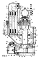
- the backwash filter shown has two parallel, upright filter chambers 1 with filter inserts arranged therein in the form of elongated filter candles 2 and a housing formed by a switch housing 3 and consisting of a cast part and carrying the filter chambers 1.
- Part of the switch housing 3 is a lower housing part 4, which on the underside of the switch housing e.g. is detachably connected via a flange connection and forms the housing foot.
- Each filter chamber 1 takes a group of e.g. six or more filter cartridges 2 arranged in parallel.
- the filter candles are e.g. made of metal spirals on which filter fabric socks are fitted.
- the switch housing 3 has a slurry inlet 5, a filtrate outlet 6 and a sludge outlet 7 vertically one above the other.
- the inlet 5 for the medium to be filtered lies above the filtrate outlet 6, the sludge outlet 7 below the filtrate outlet 6 on the lower housing part 4.
- the latter accommodates a horizontally located sludge drain valve 8, which will be described in more detail below.
- a switch element 9 Arranged in the switch housing 3 is a switch element 9, which can be rotated about a vertical axis and is designed in the manner of a rotary slide valve, by means of which the filter chambers 1 can alternately be switched from filter operation to backwash operation and vice versa.
- the interior of the switch housing 3 is subdivided into an upper trudge chamber 10, which is connected to the slurry inlet 5, and a lower filtrate chamber 11, which has the filtrate outlet 6.
- the switching element 9 has between the two aforementioned spaces on a piston-like extension 12, with which it leads in a bore in the switch housing.
- the piston shoulder 12 is provided with a peripheral seal 13.
- the switching element 9 has a foot flange 14 or the like at the lower end. with which it leads in a housing bore 15.
- the switching element 9 is guided with its shaft 16 through an axial bore of a head cover 17 and is mounted in this at 18.
- the head cover 17 closes the switch housing 3 at the top; it is detachably fastened to the switch housing 3, for example by screwing 19.
- the head cover 17 carries a switching drive 20 for switching the switching element 9.
- This consists of a rotary or swivel drive, in the present case a pneumatic rotary drive with an associated solenoid valve device 21 for reversing the switching element 9.
- the end of the switching shaft 16 of the switching element 9 points a square 22, which establishes the rotary connection with the switching drive.
- the backwash filter is equipped with more than just two filter chambers 1, it is advisable to use an electric motor as the switching drive, which preferably reverses the switching element 9 as a function of the pressure difference between the filter inlet and filter outlet, in order in this way to filter the filter chambers in Switching from filter operation to backwash operation and vice versa.
- the switching element 9 accordingly separates the filter chamber 1 to be cleaned from the filter circuit, so that the backwashing of this filter chamber can then be initiated automatically.
- the upper trüberraum 10 from the lower filtrate chamber 11 switching element 9 has an axial inner channel 23 which establishes the connection to the sludge drain 7 in the backwashing operation and which at the lower end with a leading to the sludge drain valve 8 connecting channel 24 Switch housing or its lower housing part 4 is connected.
- the switching element 9 has a control opening 25 on the circumference for controlling the channels 26 of the switching housing 3 leading to the filter chambers.
- the inner channel 23 ends above the control opening 25 in a head space widened in diameter, which forms an air buffer space 27.
- the lower filtrate chamber 11 is connected to the two filter chambers 1 in each case via an obliquely rising channel 28 which leads to the underside of the assigned filter chamber 1 or the filter insert 2 located therein.
- the filter chamber 1 in question is connected via the channel 26 to the clouding chamber 10 in filter operation. If there are more than two filter chambers 1, all of the filter chambers 1 in the filtering mode are connected via their channels 26 to the treatment room 10, correspondingly via their channels 28 to the filtrate chamber 11.
- the filter cartridges 10 located in the individual filter chambers 1, which form the filter insert, are located in the upper region in the interior of a housing hood 29 which is detachably connected with its foot to the parting plane 30 by means of screws 31 on the upper side of the switch housing 3.
- the filter inserts or the filter candles 2 are immersed from above into the interior spaces of the switch housing 3 forming the channels 26, whereby they have a length inside the switch housing 3 that corresponds to at least about a third or half their length or the relevant chamber.
- the parting plane 30 between the switch housing 3 and the removable housing hoods 29 is accordingly at a distance above the lower ends of the filter candles 2.
- the filter candles 2 are mounted in each filter chamber 1 on a candle holder 33, or the like at a distance below the parting plane 30 in a holder bearing 34. exists, loose, i.e. with the housing hood 29 removed, is supported so that it can be lifted up freely.
- the holder bearing 34 consists of a turning out of the housing wall 32 at the transition of the channel 28 to the space 26.
- the holders 33 protrude upwards over the parting plane 30 into the housing hoods 29. They consist of a basket-shaped structure which is supported by a plate-shaped foot piece 35, a spaced above it, enclosing the filter insert or filter cartridges head ring 36 and the two parts 35 and 36 connecting web parts 37 is formed at circumferential intervals.
- the filter candles 2 are inserted with their lower foot ends 39 in holes in the plate-shaped foot piece and in these e.g. fixed by screwing.
- the holder 33 is supported with the foot piece 35 in the socket 34 and is sealed by means of a sealing ring 38 in the socket.
- the housing hoods 29 each have an inner shoulder 40 which, when the housing hoods are screwed onto the switch housing 3, lies against the head ring 36 from above, as a result of which the holder 37 is fixed with the filter candles 2 attached to it.
- the holders 37 which protrude from the switch housing 3 at the top and the attached filter candles 2 can be lifted out of the switch housing 3 at the top. This makes it easy to replace the filter inserts. Since the height of the housing covers 29 is smaller than the length of the filter inserts, the housing covers 29 can be easily removed after loosening the screws 31 without the risk of damage to the filter inserts, even if only a limited clearance is available above the backwash filter at the place of use .
- a vent valve 42 controlled by a float 41 is arranged in the head space of the housing hoods 29 and its outlet is connected to a collecting line 43. All filter chambers 1 with their ventilation valves 42 are connected to the manifold 43. When the filter chambers are filled with liquid, the ventilation valves 42 are closed by their floats 41, as is known.
- the common manifold 43 can, as shown in Fig. 1 at 43 ', be connected to the sludge drain 7.
- a circumferential space 44 enclosing the latter, which is arranged above the connection channels 28 connecting the filtrate space 11 to the filter chambers 1 and which in backwashing operation in connection with the filtrate space 11 or with the connection channel 28 of the filter chamber 1 to be backwashed.
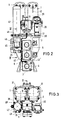
- the peripheral space 44 is connected to a compressed gas supply. This is not shown in Fig. 1. 2 to 4 show the line 45 serving for pressurized gas supply together with a flushing valve 46, which is arranged on the underside of a pressurized gas storage container 47, which in the exemplary embodiment shown is detachably connected to the parting plane 30 at its parting plane 30 by screwing 48 .
- the storage container 47 can also be installed elsewhere on the switch housing. It receives the compressed gas used for backwashing, generally compressed air, and can be charged with the compressed gas via a line 49.
- the flushing valve 46 serving the compressed gas supply consists of a compressed air operated piston valve, the valve piston 50 of which is provided with a piston seal closes an outlet arranged at the foot of the storage container 47 and is pressed by a spring 52 in the closed position.
- the valve piston 50 carries a control piston 53 which leads with a piston seal in a cylinder housing, to which a compressed air line 54 is connected, via which compressed air can be introduced into the annular space under the control piston 53 in order to pull the valve piston 50 against the restoring force of the spring 52 as far from the bore 51 that the Compressed gas located in the storage container 47 can reach the peripheral space 44 (FIG. 1) via the line 45.
- sludge drain valve 8 consists of a compressed air operated piston valve, the valve piston 55 is guided in the horizontal bore forming the sludge outlet 7 in a guide bush 56 with a piston seal, which has a circumferential opening 57, via which when the sludge drain valve is open the connection to the sludge drain 7 is established.
- a control piston 58 is connected to the valve piston 55 and leads with an easily replaceable piston seal in a cylinder 59 which is laterally detachably connected to the housing.
- an electromagnetically actuated switching valve 60 which is connected via lines 61 and 62 to the two cylinder chambers on both sides of the piston 58, so that when the annular chamber is pressurized on the piston side of the piston valve and with simultaneous ventilation of the cylinder chamber 63, the sludge drain valve opens and so that the connection to the mud drain 7 is made.
- the entire sludge drain valve 8 forms a structural unit connected to the side of the housing 3 and easily removable from the housing if required.
- the slurry to be filtered flows through the slurry inlet 5 into the trituration chamber 10 and from here to or to the filter chambers 1 switched to filter operation.
- the slurry flows in the direction of the arrow X into the relevant chamber 26, then flows through the filter candles 2 from the outside inside, filtering out the impurities.
- the filtrate then flows downward in the filter candles 2 and through the relatively large open foot ends 39 of the filter candles via the channel 28 into the filtrate space 11 and from here to the filtrate outlet 6.
- the backwashing takes place, as is known, in countercurrent.
- the switching element 9 for the filter chamber 1 shown here is switched to backwashing.
- the switching element 9 separates the filter chamber 1 to be cleaned from the filter circuit.
- the automatic backwashing starts.
- the filter chamber shut off from the slurry inlet 5 and from the filtrate outlet 6 is depressurized by first opening the sludge drain valve 8, whereby the connection of the inner channel 23 of the switching element 9 and the space 26 on the outside of the filter candles 2 with the sludge outlet 7 is established.
- the explosively relaxing compressed gas presses the flushing filtrate located on the clean side of the filter candles 2 through the filter fabric of the filter candles 2 at a high speed, the solid impurities adhering to the filter fabric being loosened and carried away by the flushing liquid and through the opened one Sludge drain valve 8 are flushed out of the filter through the sludge drain 7.
- the sludge drain valve 8 and the compressed gas feed valve 46 can be closed again automatically.
- the blown-out filter chamber is filled with a controlled amount of the filtered liquid through a filling channel until it is automatically vented.
- the filling channel mentioned which can consist of a small bore in the switching element 9, is not shown in FIG. 1. After filling the blown-out filter chamber, the cleaned filter chamber can be switched to filter operation by switching the switching element 9.
- the backwash filter according to the invention is characterized by a comparatively simple structure, by a compact design and by easy access to the various functional parts, so that the maintenance of the backwash filter is also simple. Also advantageous are the short internal flow paths and the large flow cross sections, which are not smaller in all areas than at the filter inlet.
- the compact design of the backwash filter makes it possible to increase the available filter area considerably without increasing the construction volume of the backwash filter compared to the known filters of this type.
- the switch housing 3 of the filter is characterized by a simple shape and can therefore be produced inexpensively as a cast part.
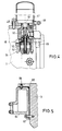
- the use of the compressed gas storage container 47 can be dispensed with if an adequate compressed air supply is available at the place of use of the backwash filter. As shown in FIG.
- heating elements 64 can be attached to the switch housing 3 on the outside.
- the switch housing 3 is expediently provided on its outside by integrally formed housing recesses 65 receiving pockets for adapted heating elements 64 which are flowed through by a heating medium (steam, thermal oil or the like.)
- the connection of the heating elements 64 to the switch housing 3 can be done by pinning 66 and / or by means of screws 67 or the like. he follows. 1 shows a single heating element 64 in its position on the circumference of the switch housing 3 in the area of the filter chamber 1.
Landscapes
- Chemical & Material Sciences (AREA)
- Chemical Kinetics & Catalysis (AREA)
- Filtering Of Dispersed Particles In Gases (AREA)
- Filtration Of Liquid (AREA)
Applications Claiming Priority (2)
| Application Number | Priority Date | Filing Date | Title |
|---|---|---|---|
| DE3832679 | 1988-09-27 | ||
| DE3832679A DE3832679A1 (de) | 1988-09-27 | 1988-09-27 | Rueckspuelfilter |
Publications (2)
| Publication Number | Publication Date |
|---|---|
| EP0361217A1 EP0361217A1 (de) | 1990-04-04 |
| EP0361217B1 true EP0361217B1 (de) | 1994-03-30 |
Family
ID=6363748
Family Applications (1)
| Application Number | Title | Priority Date | Filing Date |
|---|---|---|---|
| EP89116991A Expired - Lifetime EP0361217B1 (de) | 1988-09-27 | 1989-09-14 | Rückspülfilter |
Country Status (6)
| Country | Link |
|---|---|
| EP (1) | EP0361217B1 (zh) |
| JP (1) | JPH02187106A (zh) |
| KR (1) | KR0129762B1 (zh) |
| CN (1) | CN1028491C (zh) |
| DE (2) | DE3832679A1 (zh) |
| ES (1) | ES2053898T3 (zh) |
Cited By (1)
| Publication number | Priority date | Publication date | Assignee | Title |
|---|---|---|---|---|
| EP1484096A1 (de) | 2003-06-04 | 2004-12-08 | Boll & Kirch Filterbau GmbH | Rückspülfilter |
Families Citing this family (15)
| Publication number | Priority date | Publication date | Assignee | Title |
|---|---|---|---|---|
| FI108000B (fi) * | 1999-11-11 | 2001-11-15 | Parker Hannifin Oy | Suodatuslaitteisto |
| DE60109871T2 (de) * | 2000-02-14 | 2006-04-27 | Milow Ltd. | Generator zur Pulsierung von Fluids zum Einsatz in einer Filterreinigungsvorrichtung und dem entsprechenden Verfahren |
| DE10124476B4 (de) * | 2001-05-19 | 2014-05-28 | Man Diesel & Turbo, Filial Af Man Diesel & Turbo Se, Tyskland | Ölversorgungseinrichtung für einen Großdieselmotor |
| CN100569331C (zh) * | 2006-12-22 | 2009-12-16 | 清华大学 | 两段式抽滤液固分离器及分离方法 |
| DE102010033682A1 (de) * | 2010-08-06 | 2012-02-09 | Mahle International Gmbh | Fluidfilter |
| DE102011100518A1 (de) * | 2011-05-05 | 2012-11-08 | Hydac Process Technology Gmbh | Filtervorrichtung |
| DE102011082695A1 (de) * | 2011-09-14 | 2013-03-14 | Mahle International Gmbh | Filtergerät |
| CN102512865B (zh) * | 2011-12-20 | 2013-11-20 | 自贡科创液压有限公司 | 一种换向不截流式反冲排污油滤器 |
| CN103285646B (zh) * | 2013-06-24 | 2015-09-16 | 山西平阳广日机电有限公司 | 自动反冲洗过滤器 |
| WO2016086387A1 (zh) * | 2014-12-04 | 2016-06-09 | 苏俊 | 一种快速反冲洗过滤器 |
| CN106994266B (zh) * | 2016-01-26 | 2024-04-19 | 北京豪盛恒大科技有限公司 | 一种中央空调过滤系统及其过滤方法 |
| JP6964866B2 (ja) * | 2017-07-13 | 2021-11-10 | 東洋スクリーン工業株式会社 | 連続ろ過装置 |
| DE102017009990A1 (de) * | 2017-10-26 | 2019-05-02 | Hydac Process Technology Gmbh | Filtervorrichtung |
| CN114797197B (zh) * | 2022-03-11 | 2024-04-23 | 中科德徕环境科技(广东)有限公司 | 一种高效的反冲洗装置及冲洗方法 |
| CN115779533B (zh) * | 2023-02-06 | 2023-05-16 | 西安萃源生物科技有限公司 | 一种生物制剂制备装置及其过滤机构 |
Family Cites Families (4)
| Publication number | Priority date | Publication date | Assignee | Title |
|---|---|---|---|---|
| US3394735A (en) * | 1967-02-27 | 1968-07-30 | Andale Co | Valve member for a duplex strainer |
| DE7831128U1 (de) * | 1978-10-19 | 1979-02-15 | Boll & Kirch Filterbau Gmbh, 5000 Koeln | Rueckspuelfilter |
| DE3032690A1 (de) * | 1980-08-29 | 1982-05-06 | Agfa-Gevaert Ag, 5090 Leverkusen | Verfahren und vorrichtung zur kontinuierlichen filterung von fluessigkeiten |
| DE3115716A1 (de) * | 1981-04-18 | 1982-11-04 | Boll & Kirch Filterbau GmbH, 5014 Kerpen | "rueckspuelfilter" |
-
1988
- 1988-09-27 DE DE3832679A patent/DE3832679A1/de not_active Withdrawn
-
1989
- 1989-09-14 EP EP89116991A patent/EP0361217B1/de not_active Expired - Lifetime
- 1989-09-14 ES ES89116991T patent/ES2053898T3/es not_active Expired - Lifetime
- 1989-09-14 DE DE89116991T patent/DE58907339D1/de not_active Expired - Lifetime
- 1989-09-25 CN CN89107483A patent/CN1028491C/zh not_active Expired - Lifetime
- 1989-09-26 KR KR1019890013842A patent/KR0129762B1/ko not_active IP Right Cessation
- 1989-09-27 JP JP1249398A patent/JPH02187106A/ja active Pending
Cited By (2)
| Publication number | Priority date | Publication date | Assignee | Title |
|---|---|---|---|---|
| EP1484096A1 (de) | 2003-06-04 | 2004-12-08 | Boll & Kirch Filterbau GmbH | Rückspülfilter |
| DE10325525B4 (de) * | 2003-06-04 | 2013-10-24 | Boll & Kirch Filterbau Gmbh | Rückspülfilter |
Also Published As
| Publication number | Publication date |
|---|---|
| KR900004377A (ko) | 1990-04-12 |
| EP0361217A1 (de) | 1990-04-04 |
| CN1041537A (zh) | 1990-04-25 |
| ES2053898T3 (es) | 1994-08-01 |
| DE3832679A1 (de) | 1990-03-29 |
| JPH02187106A (ja) | 1990-07-23 |
| KR0129762B1 (ko) | 1998-04-08 |
| DE58907339D1 (de) | 1994-05-05 |
| CN1028491C (zh) | 1995-05-24 |
Similar Documents
| Publication | Publication Date | Title |
|---|---|---|
| EP0900584B1 (de) | Rückspülfilter | |
| EP0361217B1 (de) | Rückspülfilter | |
| EP2207609B1 (de) | Filtervorrichtung | |
| DE10151864B4 (de) | Verfahren zum Betrieb eines Filters für Flüssigkeiten und System zur Durchführung des Verfahrens | |
| EP1237640A1 (de) | Rückspülfiltervorrichtung | |
| DE1761106C3 (de) | Filter zur Reinigung von mit Feststoffen vermischten Flüssigkeiten | |
| EP0572369A2 (de) | Rückspülbare Filtervorrichtung zur Filtration hochviskoser Flüssigkeiten | |
| DE102007003925B4 (de) | Filteranlage | |
| DE102008052739B3 (de) | Vorrichtung zum Entfernen von organischen Bestandteilen aus dem Wasser von Aquarien | |
| EP0226659A1 (de) | Filterpresse | |
| DE19542578A1 (de) | Rückspülbare Filtervorrichtung mit Druckgas | |
| EP2039410A1 (de) | Filtervorrichtung | |
| DE10243122B4 (de) | Selbstreinigende Filteranordnung | |
| EP1243300B1 (de) | Kerzenfiltervorrichtung für die Bierfiltration | |
| DE3937378C2 (zh) | ||
| EP0807605B1 (de) | Gerät zum Entsalzen und Aufbereiten von Wasser | |
| EP0252996A1 (de) | Vorrichtung zur filtration einer fluessigkeit | |
| DE1241803B (de) | Absperrvorrichtung zum automatischen, periodischen Entschlammen von Filterkerzen durch Rueckspuelung | |
| DE4232490C2 (de) | Düsen-Rückspülfilter | |
| DE1436267A1 (de) | Rueckspuelfilter | |
| EP0655934B1 (de) | Druckfilter | |
| DE2733025A1 (de) | Filtervorrichtung und -verfahren fuer fluessigkeit | |
| EP2753408B1 (de) | Filteranlage für ein flüssiges medium | |
| AT384174B (de) | Fluessigkeits-, insbesondere wasserfiltriereinrichtung mit kontinuierlicher spuelung | |
| DE4217666A1 (de) | Fluessigkeitsfilter |
Legal Events
| Date | Code | Title | Description |
|---|---|---|---|
| PUAI | Public reference made under article 153(3) epc to a published international application that has entered the european phase |
Free format text: ORIGINAL CODE: 0009012 |
|
| AK | Designated contracting states |
Kind code of ref document: A1 Designated state(s): DE ES FR GB IT NL SE |
|
| 17P | Request for examination filed |
Effective date: 19900215 |
|
| 17Q | First examination report despatched |
Effective date: 19920525 |
|
| ITF | It: translation for a ep patent filed | ||
| GRAA | (expected) grant |
Free format text: ORIGINAL CODE: 0009210 |
|
| AK | Designated contracting states |
Kind code of ref document: B1 Designated state(s): DE ES FR GB IT NL SE |
|
| REF | Corresponds to: |
Ref document number: 58907339 Country of ref document: DE Date of ref document: 19940505 |
|
| GBT | Gb: translation of ep patent filed (gb section 77(6)(a)/1977) |
Effective date: 19940518 |
|
| ET | Fr: translation filed | ||
| REG | Reference to a national code |
Ref country code: ES Ref legal event code: FG2A Ref document number: 2053898 Country of ref document: ES Kind code of ref document: T3 |
|
| EAL | Se: european patent in force in sweden |
Ref document number: 89116991.4 |
|
| PLBE | No opposition filed within time limit |
Free format text: ORIGINAL CODE: 0009261 |
|
| STAA | Information on the status of an ep patent application or granted ep patent |
Free format text: STATUS: NO OPPOSITION FILED WITHIN TIME LIMIT |
|
| 26N | No opposition filed | ||
| REG | Reference to a national code |
Ref country code: GB Ref legal event code: IF02 |
|
| PGFP | Annual fee paid to national office [announced via postgrant information from national office to epo] |
Ref country code: ES Payment date: 20080922 Year of fee payment: 20 |
|
| PGFP | Annual fee paid to national office [announced via postgrant information from national office to epo] |
Ref country code: NL Payment date: 20080922 Year of fee payment: 20 Ref country code: IT Payment date: 20080926 Year of fee payment: 20 Ref country code: FR Payment date: 20080917 Year of fee payment: 20 |
|
| PGFP | Annual fee paid to national office [announced via postgrant information from national office to epo] |
Ref country code: GB Payment date: 20080922 Year of fee payment: 20 |
|
| PGFP | Annual fee paid to national office [announced via postgrant information from national office to epo] |
Ref country code: DE Payment date: 20080818 Year of fee payment: 20 |
|
| PGFP | Annual fee paid to national office [announced via postgrant information from national office to epo] |
Ref country code: SE Payment date: 20080923 Year of fee payment: 20 |
|
| REG | Reference to a national code |
Ref country code: GB Ref legal event code: PE20 Expiry date: 20090913 |
|
| NLV7 | Nl: ceased due to reaching the maximum lifetime of a patent |
Effective date: 20090914 |
|
| EUG | Se: european patent has lapsed | ||
| REG | Reference to a national code |
Ref country code: ES Ref legal event code: FD2A Effective date: 20090915 |
|
| PG25 | Lapsed in a contracting state [announced via postgrant information from national office to epo] |
Ref country code: GB Free format text: LAPSE BECAUSE OF EXPIRATION OF PROTECTION Effective date: 20090913 Ref country code: NL Free format text: LAPSE BECAUSE OF EXPIRATION OF PROTECTION Effective date: 20090914 |
|
| PG25 | Lapsed in a contracting state [announced via postgrant information from national office to epo] |
Ref country code: ES Free format text: LAPSE BECAUSE OF EXPIRATION OF PROTECTION Effective date: 20090915 |