EP0360698B1 - Procédé et dispositif d'estimation de mouvement dans une séquence d'images animées - Google Patents
Procédé et dispositif d'estimation de mouvement dans une séquence d'images animées Download PDFInfo
- Publication number
- EP0360698B1 EP0360698B1 EP89402603A EP89402603A EP0360698B1 EP 0360698 B1 EP0360698 B1 EP 0360698B1 EP 89402603 A EP89402603 A EP 89402603A EP 89402603 A EP89402603 A EP 89402603A EP 0360698 B1 EP0360698 B1 EP 0360698B1
- Authority
- EP
- European Patent Office
- Prior art keywords
- displacement
- image
- calculating
- point
- frame
- Prior art date
- Legal status (The legal status is an assumption and is not a legal conclusion. Google has not performed a legal analysis and makes no representation as to the accuracy of the status listed.)
- Expired - Lifetime
Links
Images


Classifications
-
- H—ELECTRICITY
- H04—ELECTRIC COMMUNICATION TECHNIQUE
- H04N—PICTORIAL COMMUNICATION, e.g. TELEVISION
- H04N5/00—Details of television systems
- H04N5/14—Picture signal circuitry for video frequency region
- H04N5/144—Movement detection
- H04N5/145—Movement estimation
-
- G—PHYSICS
- G06—COMPUTING; CALCULATING OR COUNTING
- G06T—IMAGE DATA PROCESSING OR GENERATION, IN GENERAL
- G06T7/00—Image analysis
- G06T7/20—Analysis of motion
- G06T7/269—Analysis of motion using gradient-based methods
-
- H—ELECTRICITY
- H04—ELECTRIC COMMUNICATION TECHNIQUE
- H04N—PICTORIAL COMMUNICATION, e.g. TELEVISION
- H04N19/00—Methods or arrangements for coding, decoding, compressing or decompressing digital video signals
- H04N19/50—Methods or arrangements for coding, decoding, compressing or decompressing digital video signals using predictive coding
- H04N19/503—Methods or arrangements for coding, decoding, compressing or decompressing digital video signals using predictive coding involving temporal prediction
- H04N19/51—Motion estimation or motion compensation
- H04N19/523—Motion estimation or motion compensation with sub-pixel accuracy
Definitions
- the invention relates to a method and a device for estimating motion in a sequence of moving images.
- the object of the invention is to overcome the aforementioned drawbacks.
- the subject of the invention is a method of estimating movement according to claim 1.
- a subject of the invention is also a first and a second device for implementing the above-mentioned method, according to claims 7 and 23.
- the main advantage of the method and the device according to the invention is that they allow, through the additional use of a time initialization vector, an increase in the speed of convergence of the gradient algorithm.
- the resulting displacement estimate allows a better temporal interpolation because there is continuity in the displacement fields. The risks of false estimates which result in jumps of images very troublesome for the eye are thus limited.
- the method according to the invention which is described below is based on the use of a displacement estimation algorithm of the type described in an article in the publication BELL SYSTEM TECHNOLOGIE volume 58 pages 631 to 670 from MARS 1979 Part.1 entitled "Motion compensated television coding” and author A.N NETRAVALI and JD. ROBBINS.
- the gradient algorithm developed there minimizes the quadratic deviation of the local variations in luminance of each current point of a television image between the current point and the point which is homologous to it in the previous image.
- s is defined by the relation: or with the condition that if:
- the method according to the invention uses the inter-frame differences existing between two image frames Ta and Tb in a sequence of images, the unit of time considered being the image period, the frames Ta and Tb being designated subsequently by their shooting instants.
- the movement is estimated, as shown in FIG. 1a, between two frames Ta and Tb from the points of Ta and Tb for the pixels of one of the two frames Ta or Tb (Tb in Figure 1a).
- the field of movement obtained is therefore assigned to the frame Ta or to the frame Tb (Tb in FIG. 1a).
- the displacement vector De of each pixel of horizontal and vertical luminance component IX and IY is defined by relations of the form or
- each displacement vector D e (z, Tb) of a current point in the frame Tb has a pivoting end on a pixel of the frame Tb and a free origin end in the frame Ta.
- the fields of the displacement vectors D e (z, Tb) are associated with the pixels of the frame Tj, and a calculation of interpolation allows knowing D e (z, Tb) to define D (z, Tj).
- the movement is estimated between the frames Ta and Tb directly for each point of luminance components (IX, IY) of a fictitious intermediate frame Tj.
- the interpolation method By having the displacement vector D of each pixel of coordinates (IX, IY, Tj) in the frame Tj, the interpolation method then provides the reconstruction values for each point (IX, IY, Tj) of the frame Tj without requiring an additional step of association of movement with the frame Tj.
- this process quickly becomes very time-consuming since it requires an estimation of the movement between each frame Ta and Tb for each of the images Tj, it could then be preferable to opt in favor of the first type of estimate indicated above.
- the displacement vector D (z, Tj) of each pixel P (z, Tj) of a frame Tj therefore pivots around its pixel and at its ends carried respectively on the frames Ta and Tb, a representation of this variant is shown in Figure 1b.
- This configuration makes it possible to use the motion field obtained by motion estimators comprising a frame interpolator adapted to the motion.
- the frames Ta, Tb and Tj may be of even or odd parity; even frames are simply shifted vertically by half a line with respect to odd frames (and temporally by half an image period): line 1 of the even frame is equidistant from lines 1 and 1 + 1 of the odd weft. This must be taken into account when matching two frames by adequate addressing.
- each current IMS frame (t) (Tb) is analyzed point to point by scanning each line.
- step 3 determines whether the value of the gradient found is greater than the threshold Sg. If in step 3 the value of the gradient found is greater than the threshold Sg, the method executes the processing indicated in step 5 to estimate four new displacements from four initial values of displacement in the causal neighborhood of the point current. At the end of the execution of step 5, the method proceeds to the execution of step 6 and chooses a displacement from the four displacements which were estimated in step 5. The method takes place thus by successive iterations, each end of execution of steps 4 or 6 causing in step 7 the initialization of the next point and the displacements are recorded in step 8.
- the estimated displacement is limited in the image in rows and columns within a rectangle of coordinates iDX MAx and iDY MAx relative to the current point.
- the area for estimating the movement in the current image Tb is limited as shown in FIG. 3, by maximum displacement values DXMAX and DYMAX in the horizontal direction X and the vertical direction Y of the image.
- the search for the displaced point is done throughout the previous image (Ta).
- a test can be added to verify that the mobile end of the vector is actually located on the frame of time Ta. If this is not the case, it is easy to modify this vector so as to have for the current pixel a new vector, the closest to the old, which has its mobile end on Ta, so as to be able to estimate the DFD and gradL functions.
- Each point of Tb except the points outside the window defined above, has a local window search for the end of the vector on Ta, which is centered on the current point and whose horizontal and vertical dimensions are 2DX MAX and 2DY MAX respectively .
- the displacements which are estimated in the closest causal neighborhood of the current point are used to initialize the motion estimation algorithm.
- This causal neighborhood contains four displacements which are used to initialize four estimates of motion in parallel.
- the propagation of the estimate follows in the process the normal scanning of television images. However, to avoid favoring a direction of propagation in the image from left to right for example, the scanning direction is reversed every other line alternately.
- a representation of this scanning in alternating even and odd lines is shown in FIG. 4a and the initial values D6, D6, D6 and Dg for the odd and even lines are represented respectively in FIGS. 4b and 4c.
- the threshold Sg is the threshold used on the modulus of the current gradient.
- the unit of displacement in X is formed by the interval separating two points on the same line and the unit of displacement in Y is formed by the interval separating two lines in the same frame.
- the gradients are calculated according to the known method described in the article IEEE Trans. on Com., vol. com.32, n ° 8 of August 1984 having for title "Movement compensated inter-frame prediction for NTSC color TV signals" and having for author S. SABRI.
- Figure 6 represents displacements in the previous IMS image (t-1).
- the luminance I B of the current point displaced in the previous image is obtained by bilinear interpolation of the luminances I n of the neighboring points, which is expressed with the notations of FIG. 6 by the relation
- the horizontal gradient is:
- the search area in a frame of the IMS image (t-1) for a current point P (z, t) is defined in a rectangle of dimension 30 ⁇ 10 as shown in FIG. 7.
- the four displacement estimates are carried out in parallel from the 4 initial values D , D , D and D .
- the decision criterion then consists in choosing the displacement which among the values D , , and gives the lowest absolute value of the displaced inter-image difference DFD (z, D o ). In the event of a tie, the choice is made in order D , D , and D (steps 9 to 15 of figure 8). However, if the inter-image difference displaced by the chosen displacements is not less than or equal to the threshold S (step 16) (convergence test threshold) the displacement takes the value 0 (step 17).
- the displacement selected is the first which gives a
- Each iteration i (0 ⁇ i ⁇ i MAX ) is thus associated with a displacement D i , an displaced inter-image difference DFD and a number of iteration i.
- the decision is then taken on the lowest number of iterations, then on the minimum inter-image difference displaced DFD, to then possibly make an arbitrary choice.
- the method allows the determination of a field of movement between two generally successive frames of a sequence of images, in the form of a vector field assigned to a fictitious frame located usually between the two mother frames.
- the motion field is made up of a set of vectors. Each vector passes through a pixel of the fictitious frame and has its ends on the two parent frames which surround it.
- the mother frames are designated by their instant of shooting Ta and Tb.
- the fictitious frame is located at an instant Tj intermediate between the instants Ta and Tb.
- the aim is to provide a displacement vector for each pixel of the fictitious frame considered at time Tj, the luminance of each pixel being a priori unknown, from the luminance field of the frames of instants Ta and Tb.
- the instant Tj can also be located outside of the interval (Ta, Tb).
- This method is similar to the method described above corresponding to the first alternative embodiment of the invention with the difference, however, that it makes it possible to estimate the movement between two frames of instants Ta or Tb for the pixels of the fictitious frame Tj.
- the complexities of the algorithm and that of the resulting estimation device are of the same order.
- the motion estimate is calculated from the luminance L () of the pixels of the time frames Ta and Tb.
- the estimated motion for each pixel is in the form of a vector D with two horizontal components DX and vertical DY.
- the estimate is calculated between two frames Ta and Tb which can be of the same parity or of different parity, and for a frame Tj which can also be even or odd.
- a correcting vector, designated by dza or dzb, is introduced into the calculation of the functions DFD and grad L. dza depends on the relative parity of Ta and Tj, dzb depends on the relative parity of Tb and Tj.
- the method uses the inter-frame differences existing between two frames of instants Ta and Tb which follow each other directly or not in a sequence of images.
- the displacement of each pixel of the fictitious frame of instant Tj is rectilinear between two frames of instants Ta and Tb, and each object element of the fictitious frame of instant Tj (luminance pixel) is also assumed to be present in the time frames Ta and Tb.
- each point of the current frame is analyzed, by a scanning in lines of all the points of the frame.
- the method performs the processing indicated in step 19 to estimate four displacement values from four initial displacement values in the causal neighborhood of the current point.
- the method proceeds to the execution of step 20 and chooses a displacement from the four displacements which were estimated in step 19.
- the method is thus proceeds by successive iterations, each end of execution of step 20 causing the initialization of the next point (step 21) and the displacements are recorded in step 22.
- the displacements which are estimated in the closest causal neighborhood of the current point are used to initialize the motion estimation algorithm.
- This causal neighborhood contains four displacements which are used to initialize four estimates of motion in parallel.
- the scanning direction is reversed every other line alternately.
- the unit of displacement in X is formed by the interval separating two points on the same line and the unit of displacement in Y is formed by the interval separating two lines in the same frame.
- the gradients are calculated as described below, and illustrated by FIG. 11 which represents a portion of the frame of time Ta, and a displacement vector whose end on the frame of time Ta has the coordinates (z -DA, Ta) and has the luminance LA.
- the luminance LB of its end in the frame of time Tb, and the displacement vector DB at this point are calculated in the same way.
- the luminance LAdu current point displaced in the frame of instant Ta is obtained by bilinear interpolation of the luminances Ln of the neighboring pixels, which is expressed with the notations of FIG. 11 by the relation:
- the displaced inter-frame difference is calculated by the relation:
- DMAX being fixed, DA MAX and DB MAX depend on the distance from the frame of time Tj to the frames of times Ta and Tb.
- the search area in the time frames Ta and Tb for a current point P (z, Tj) is then defined by a rectangle on each frame Ta and Tb as shown in Figures 12 and 19 of respective dimensions: and
- a test can be added to verify that the ends of the vector are actually located on the frames of instants Ta and Tb. If this is not the case, it is easy to modify this vector so as to have for the current pixel a new vector, the closest to the old, which has its ends on the frames of instants Ta and Tb, so that we can estimate the DFD and grad L functions.
- the four displacement estimates are carried out in parallel from 4 initial values .
- the method gives four values of DFD (D) which are compared with the threshold S.
- the displacement selected is the first which gives the value DFD less than or equal to the threshold S. If several displacements have a value DFD less than or equal to S at the same iteration, the one which gives the lowest inter-displaced frame difference DFD is chosen . In the event of a new equality on the value of DFD, an arbitrary choice is made in the order:
- the decision is made on the lowest number of iterations, then on the minimum displaced DFD inter-frame difference, then then according to possibly an arbitrary choice.
- the methods described above must be modified in their initialization phase to introduce an additional time displacement vector; the difficulty being, in order to propagate an estimation time, to find in the preceding estimated field of motion, the displacement which best suits the point current where the displacement estimation algorithm is applied.
- a first method it is possible to use as initial value, the displacement of the point with the same spatial coordinates in the previous estimated field of motion, as shown in FIGS. 13a and 13b.
- this method is only valid if the displacements from one image to another are small and it would not be necessary for example to attribute to the current point a false initial value, which would have the consequence of introducing additional inaccuracies in the motion estimation.
- the first method is of little interest insofar as it can introduce inaccuracies.
- the initial time value is very easily obtained: it suffices to read the movement assigned to the point with the same spatial coordinates in a movement memory of the previous image.
- the second method is more efficient: the displacements estimated between the frames Ta and Tb for the points of a fictitious frame Tj-1 or for the points of the frame Ta or of the frame Tb are projected according to their direction towards the following frame, whose movement we want to estimate respectively towards the frame Tj or towards the frame Tb or Tc, to form the prediction image.
- This gives the initial time prediction motion field used to estimate the displacement between Tc and Tb for the points of the frame Tj or for the points of the frame Tb or the frame Tc.
- the previous frame Tx-1 hypothetically contains a motion field defined by motion vectors with two components ( DX and DY) at each of its points.
- the field of motion is defined in these conditions for all the points of the frame Tx if there exists at each point of the frame Tx a corresponding point in the frame Tx-1.
- the ideal case is a bijection of the points of the Tx-1 frame to those of the Tx frame, each point of the Tx frame in this case having one and only correspondent in the Tx-1 frame.
- the movement between the frames Tj-1 and Tj is linear, and each displacement vector of the frame Tj-1 is extended to the frame Tj where it creates a point of intersection.
- intersection points There are thus as many points of intersection as there are pixels in the frame Tj-1, some of which may possibly be confused. Each of these intersection points is thus associated with the movement vector which created it, and therefore each intersection point carries information providing information on the movement of the points of the frame Tj.
- the problem then becomes that of defining what is the motion prediction to be given to the pixels of the frame Tj from the displacement vectors of the intersection points also located on the frame Tj.
- the pixel of coordinates closest to that of the point of intersection C is assigned the displacement vector of the point C, as can be seen in the examples represented in FIGS. 13c and 13d.
- the displacement vector Dô (P, Tj) which is assigned to the point P is in these conditions equal to the displacement vector D (B, Tj-1) of point B in the frame Tj-1.
- the solution which is adopted consists in calculating the temporal difference in the direction of movement between the frames Tc and Tb per displacement vector received, retaining as temporal prediction only the displacement which gives the smallest DFD difference.
- a second solution may for example consist in considering only keeping the first movement which occurs: that is to say that when a point in the frame Tj has received a movement, it will no longer be able to receive d 'other.
- this solution seems quite critical since it is not possible to judge whether the first movement which is attributed to the point is suitable as an initial value.
- this solution requires performing a test at each point to find out whether a movement has been allocated or not at this point.
- the processing of the holes takes place in the following manner: As indicated previously, it may happen that certain pixels of the frame Tj are not assigned any movement (FIG. 13f). These holes in the predicting motion field are filled by spatial interpolation of the motion vectors from the nearest neighborhood. To do this, when the method has associated the pixels closest to the points of impact with the corresponding movements, it searches for the holes in the prediction field of the frame Tj thus obtained, by alternating the horizontal scanning direction every other line .
- FIGS. 15a and 15b When it is in the presence of a hole four points in the vicinity are then considered as shown in FIGS. 15a and 15b.
- the points of the causal neighborhood (Ad on the one hand, B or C depending on the horizontal scanning direction on the other hand) have already been treated, and that they have a motion vector .
- points C or B and point D may not have a motion vector and may also be holes. In this case, they are not taken into account for the interpolation.
- the method attributes to the hole the movement resulting from the average of the motion vectors of the points of the spatial neighborhood. This calculation is done at best with four motion vectors (points A, B, C and D) at worst with two motion vectors (points A, and B or C depending on the scan, C or B and D also being holes).
- the time prediction process for displacement estimators between Tc and Tb frames for points belonging to a Tc or Tb frame is similar.
- the movement of pixel B of spatial coordinates (X, Y) in the frame Tb can be assigned to a point C of the frame Tc, of spatial coordinates (X1, Y1) which is the point of impact on this frame of the motion vector assigned to the point B.
- the coordinates (X1, Y1) verify the relationship: where DX, DY denote the components of the displacement vector D of point B in the frame Tb and DEY denotes the possible vertical shift between the frames Tb and Tc (if frames of different parities).
- point C does not generally correspond to a pixel, it is the pixel closest to point C which is assigned the motion vector of point C:
- a first stage 23 consists in memorizing the displacement vectors of the points of each frame Tj-1 or Tb to extend in stage 24 the displacement vectors in order to determine their points of impact on the Tj or Tc frames.
- the displacement vectors are allocated to the pixels closest to the impact points and the conflicts between vectors arriving at the same impact points are resolved.
- the processing of the holes takes place in step 26 and the storage of the motion fields for the frames Tj or Tc is carried out in step 27.
- each point of the current frame is considered by scanning each line of this frame.
- the method performs the processing indicated in step 19 to estimate 5 new displacements from four initial displacement values determined in the causal vicinity of the current point, and from an initial time prediction value defined in step 28
- the method proceeds to the execution of step 20 and chooses a displacement among the 5 displacements which were estimated in step 19.
- the method is thus proceeds by successive iterations, each end of execution of step 20 causing the initialization of the next point and the displacements are recorded in step 22.
- the five displacement estimates are carried out in parallel from the 4 initial spatial values and the initial value DP0.
- the displacement selected is the first which gives a
- the decision is then taken on the lowest number of iterations, then on the minimum inter-image difference displaced DFD to then possibly make an arbitrary choice.
- each point of a current frame Tc is considered on the flowchart in Figure 20 by scanning each line of this frame.
- the modulus of the gradient at the current point grad P (z, t) is calculated in step 2.
- the choice of a displacement is done as shown in FIG. 21 among five initial values, the choice of the four spatial displacement values being carried out according to steps 9 to 17 identical to those represented in FIG. 8 and the choice of the time displacement value being effected by the execution of steps 30 and 31.
- the displacement selected is that which among the displacements gives the smallest inter-displaced image difference. In the event of a tie, the choice is made in order . However, if the displaced inter-image difference is not less than or equal to the convergence threshold S, the chosen displacement is reset to zero.
- the five displacement estimates are carried out in parallel from the four initial spatial values. and the initial time value .
- the displacement selected is the first which gives a
- the decision is made on the lowest number of iterations, then on the minimum inter-image difference displaced DFD to then possibly make an arbitrary choice.
- the alternation of the direction of propagation of the movement from one frame to the next can be obtained by rotation.
- the relations (1) and (24) described previously define a relation between the horizontal and vertical components of the movement Dx and Dy, the spatial gradients of the horizontal luminance GX and vertical GY, and the temporal gradient in the direction of an initial DFD move and the correction function of equation (1) D determines a particular solution of this equation: with
- This modification is particularly important when, for example, the prediction vector is not available. on the same line as the current point, or more generally, when the number of prediction vectors is reduced to 1 or when the choice of these reduces the angular arc of propagation of the movement by recursion by reducing the spatial interdependence of the estimated vectors.
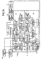
- FIG. 22 An exemplary embodiment of a first displacement estimation device implementing the phases of the method represented in FIGS. 20 and 21 is now described with the aid of FIGS. 22 to 24. It consists in FIG. 22 of a set of line memories 32, of an image memory 33, of a device for determining the direction of scanning and of calculating the modulus of the current gradient 34, of a switching device 35, of the decision-making bodies 36 and 37 and displacement estimation 38, an initialization device 39 and a time prediction device 40 coupled to memories of predicted movements 41 and 42.
- the device for determining the scanning direction and for calculating the module of the current gradient 34 receives its information from all of the line memories 32 and supplies the result of the calculations to the displacement estimation device 38 and to the routing device 35.
- the displacement estimation device 38 has two inputs which are connected on the one hand, to the output of all the line memories 32 through the device for determining the direction of scanning and for calculating the current gradient 20 and on the other hand, to the output of the image memory 33.
- the line memory 32 serves as a buffer to the image memory 33 for storing the refresh information of the image memory 33 while waiting for the points analyzed to be outside the exploration window. With an exploration window occupying a space of 10 lines of the type described in FIG. 7, a line memory having a storage capacity for points corresponding to 5 successive lines seems sufficient.
- the calculations carried out take place at the point frequency, at the rate of clock pulses H and H k supplied by a line clock not shown.
- the device 34 determines the number of the current line 1 and as a function of the parity of the number of the current line 1 it determines the number of the column of the current point k. Then having the coordinates (k, l) of the current point, the device 34 calculates the modulus of the current gradient.
- the switching device 35 compares the result of the calculation supplied by the device 34 to a reference threshold Sg and in accordance with the algorithm represented in FIG. 20 validates its input 1 or 2. Input 1 is chosen if grad I ( z, t) ⁇ Sg and input 2 is chosen if grad I (z, t)
- the decision-making bodies 36 and 37 have the functionalities described by the flowchart of FIG. 21, and can be carried out in a known manner, either using a microprogrammed structure of the microprocessor type, or even using 'a wired logic composed in a known manner by comparator circuits.
- FIG. 23 An embodiment of a displacement estimation device 38 is represented in FIG. 23. It consists of a calculation unit formed by the elements 43 to 67. The latter provides the displacement information to the decision-making body 36 which transmits them to input 2 of the switching device 35, FIG. 22.
- the initialization block 39 also shown in FIG. 23 makes it possible to initialize the displacement calculation algorithm.
- Block 39 includes a first register 68 and a second register 69. These registers are formed of three distinct parts, one for storing binary words representing the displacement word in x or in y called MDX and MDY respectively, another to serve as buffer memory to the displacement words MTDX and MTDY calculated by the decision member 36 and the last one for storing the temporal displacement prediction words MPDX and MPDY.
- MTDX and MTDY are used as intermediaries before overwriting the words MDX and MDY corresponding to the displacements D (k-1, 1-1) for the passage to the analysis of the next point (k + 1, 1). They also serve as in intermediate before overwriting the words MDX and MDY corresponding to the displacements D (k + 1, l-1) for the passage to the analysis of the next point (k-1, l).
- the estimated displacement D (FC, I) is automatically placed in the words (MTDX, MTDY) as well as in the words of (MDX, MDY) corresponding to the displacements D (FC, I) and D ( HR + 1, 1).
- the estimated displacement D (DC, I) is automatically put in the words (MTDX, MTDY) as well as in the words of (MDX, MDY) corresponding to the displacements D (DC, I) and D ( DC-1,1).
- the device for calculating the displacement estimates composed of the elements 43 to 67, performs five displacement calculations in parallel from four initial values , contained in the initialization block 39 when the spatial gradient of the current image is greater than the threshold Sg defined above.
- Information are applied respectively to the first inputs of the routing circuits 43, 48, 53, 68 and 63, the outputs of which are connected to convergence test blocks and calculation of correction terms noted respectively (44,45), (49,50 ), (54.55), (59.60) and (64.65).
- the results of the convergence tests and the calculation of the correction terms are applied to inputs of referral devices denoted respectively 46, 51, 56, 61 and 66 which then direct them, or to respective inputs of the decision-making body 36, or on devices for calculating new displacements, denoted respectively 47, 52, 57, 62 and 64, when the resolution of the algorithm described above diverges for i less than i MAX .
- the new displacements provided by the calculation devices 47, 52, 57, 62 and 67 are applied respectively to the second inputs of the switching devices 43, 48, 53, 68 and 63.
- the convergence test block 44 comprises on the one hand, an interpolation circuit 70 coupled to a device 71 for calculating the absolute value of the displaced inter-image difference
- the interpolation circuit 70 optionally formed by a programmable read-only memory, is also coupled to the image memory 33.
- the block for calculating the correction terms 45 comprises a device 76 for calculating the value s described above coupled with a increment calculation device 77 and a correction calculation device 78, as well as comparator circuits 79 and 80.
- the block for calculating new displacements 47 comprises subtractor circuits 81 and 82 both coupled to a comparator circuit 83.
- the coupling between the convergence test block 44 and the block for calculating the correction terms 45 is carried out by the switch 46 of FIG. 23.
- the input of the switch 46 is directly coupled to the output of the calculation device 75 and to the output of the calculation device 71 through switches 72 and 73.
- the initialization block 39 is coupled to the convergence test block 44 via the switch 43. This switch connects the initialization block 39 on the one hand, to a first input of the interpolation circuit 70 and on the other hand, to a first input of the calculation device 74.
- the second input of the switch 43 is also coupled to the output of the calculation block of the new displacement 47 which is formed by the comparator circuit 83.
- the operation of the displacement estimation device is as follows. For each of the current points of the image, the switch 43 transmits an initial value D o , found in the register 39, to the interpolation circuit 70 and to the gradient calculation device 74. A bilinear interpolation calculation on the value D o is performed by the interpolation circuit 70 to determine the luminance of the current point displaced in the previous image I (zD o , t-1). The displaced inter-image difference DFD (z, D o ) and its absolute value are calculated by the calculating device 71 from the luminance information of the current point. The switch 72 transmits the value calculated by the calculation device 71 to the decision-making body 36 when the value obtained is less than or equal to the threshold S previously defined i.
- are applied to the inputs of the decision-making device 36. Otherwise, the result provided by the calculation device 71 is applied to the input of the switch 73 then to that of the decision-making device 36 when the value of l iteration i is equal to the maximum iteration value i MAX . On the other hand, when the value of the iteration i is less than the maximum value, the result is applied to the inputs of the correction calculation block 45 through the switch 46.
- the switch 46 directs the result obtained either towards the decision-making body 36 if the value of G2 obtained is less than or equal to a coefficient value equal for example to 0.125, or to the calculation block correction terms for new displacements 45 and 47.
- the value of the iteration i is increased by one unit by the increment calculation device 77 and is reset to zero on analysis of the next current point.
- the calculation of the terms (TC) x and (TC) Y of correction in X and Y is carried out by the circuit 78.
- the values (TC) x and (TC) Y obtained on the outputs of the computing device 78 verify the relationships and
- the values (TC) x and (TC) Y obtained are applied respectively to the inputs of the comparator circuits 79 and 80 so as to be limited, except for sign conditions, to maximum and minimum values.
- the minimum values of (TC) x and of (TC) y are the same and fixed at 1/16, on the other hand the maximum value of (TC) x is fixed equal to 3 and the maximum value of (TC) y is fixed equal to 2.
- the terms (TC) x and (TC) y obtained are added to the displacement values of by the subtractor circuits 81 and 82 and the results obtained D; and Df which correspond to the estimated displacements are again limited by the comparator circuit 83 before being applied to the second input of the switch 43.
- the switch 43 applies the estimated displacements ; and to circuits 70, 74, 81 or 82.
- a displacement is chosen for the current point and is written in the buffer memory 39 containing the words MTDX and MTDY. i is reset and the switch 43 returns to its starting position and the calculations described above are repeated to estimate the displacement of the new current point.
- FIGS. 25 and 26 An exemplary embodiment of a second displacement estimation device implementing the phases of the method represented in FIG. 18 is shown in FIGS. 25 and 26.
- the device represented in FIG. 25 essentially differs from the example described in FIG. FIG. 22 by the fact that it has only one decision-making body 36 and that it does not have a referral device 35. In this way elements similar to those of FIG. 22 are represented with the same references.
- the device for estimating new displacements has a structure similar to that which has been described with the aid of FIG. 23 only slightly differs from the structure of the device for calculating displacement estimates, a corresponding embodiment of which is represented in FIG. 26.
- the difference relates essentially to the use of two interpolation circuits 70 and 70 bis and two calculation devices 74 and 74 bis instead of only one of these.
- the operation of the displacement estimation device is as follows. For each of the current points of the image, the switch 43 transmits an initial displacement value D o , found in the registers 39 to the interpolation circuits 70 and 70 bis and the gradient calculation devices 74 and 74 bis. The value D o initializes the estimate.
- a bilinear interpolation calculation is performed, on the one hand, by the interpolation circuit 70 to determine the luminance L (z-Dox (Tj-Ta) / (Tb, Ta), Ta) of the current point (z, Tj) moved in the previous frame of instant Ta by the value D o x (Tj-Ta) / (Tb-Ta) and on the other hand, by the interpolation circuit 70 bis to determine the luminance L (z + D o x (Tb-Tj) / (Tb, Ta), Tb)) of the same current point moved this time in the next frame Tb by the value D o x (Tb-Tj) / (Tb-Ta).
- the displaced inter-frame difference DFD (z, D o ) and its absolute value are calculated by the calculation device 71.
- the switch 72 transmits the value calculated by the calculation device 71 to the decision-making body 36 when the value obtained is less than or equal to the threshold S previously defined.
- the displacement D o and the absolute value of the displaced inter-frame difference DFD (D o ) are applied to the inputs of the decision-making organ 36. Otherwise, the result provided by the calculation device 71 is applied to the input of the switch 72 then to that of the decision-making body 36, when the value of the iteration i is equal to the maximum iteration value i MAX .
- the result provided by the calculation device 71 is applied to the inputs of the correction calculation block 45 through the switch 46.
- the relative parities of the frames of the instants Ta and Tj are taken into account in the circuits 70 and 74 and the relative parities of the frames of the instants Tb and Tj are taken into account in the circuits 70a and 74a.
- the switch 46 directs the result obtained either towards the decision-making body 36 if the value of G2 obtained is less than or equal to a coefficient value equal for example to 0.125, or to the calculation block correction terms for new displacements 45 and 47.
- the calculation device 76 calculates as previously the value defined above.
- the value of the iteration i is increased by one unit by the increment calculation device 77 and is reset to zero on analysis of the next current point.
- the computation of the terms (TC) x and (TC) Y of correction in X and Y is carried out by the circuit 78.
- the values (TC) x and (TC) Y obtained on the outputs of the computing device 78 verify the relationships and
- the values (TC) x and (TC) Y obtained are applied respectively to the inputs of the comparator circuits 79 and 80 so as to be limited, except for sign conditions, to maximum and minimum values.
- the minimum values of (TC) x and of (TC) Y are the same and fixed at 1/16, on the other hand the maximum value of (TC) x is fixed at 3 and the maximum value of (TC) Y is fixed equal to 2.
- the terms (TC) x and (TC) y obtained are added to the displacement values of and by circuits 81 and 82 and the results D; and Df which correspond to the estimated displacements are again limited by the comparator circuit 83 before being applied to the second input of the switch43.
- the switch 43 applies the estimated displacements D; and Df on circuits 70, 70 bis, 74, 74 bis, 81 and 82.
- a displacement is chosen for the current point and is written in the zones MTDX and MTDY of the buffer memory 39.
- the value of the iteration i is reset to zero, the switch 43 returns to its starting position and the calculations described above are repeated to estimate the displacement of the new current point.
- FIG. 27 An embodiment of a time prediction device is shown in FIG. 27. It includes a calculation device 84 coupled to two memories 85 and 86 through a switch 87. The outputs of memories 85 and 86 are connected to another calculation device 88 through a switch 89.
- the calculation device 84 is formed by a read-only memory or any equivalent device and is addressed by the estimated current motion vector. It calculates the point of impact in the next image or frame, and the pixel closest to this point of impact, with which it associates the current motion vector.
- the switch 87 directs this vector to one of the memories 85 or 86. These memories 86 and 87 are mounted in "Flip-Flop". At the output of these, the switch 89 chooses the memory which is in reading.
- the calculation device 89 detects and plugs the holes in the temporally predicted field of motion.
- the output of the computing device 88 is connected to the initialization block 39. In this device, the resolution of conflicts is done simply by overwriting by the new vector associated with the current point of the previous vector associated with this point.
- an improvement in the preceding calculation methods may consist in having the calculations executed in only one iteration by limiting the calculations of spatial gradients to the examination only of the luminances of the four points closest to the end point of the displacement vector located in the current frame.
- the method is then summed up, in calculating, in a single iteration and for each estimated displacement vector Dp j , a value DFD (D j ) of inter-image difference displaced between the luminance of the current point and its luminance value in the previous frame shifted by the distance Dp j , compare the DFD values obtained with each other to select the estimated displacement vector Dp j which corresponds to the lowest DFD value (Dp j ) and calculate the current displacement vector D j by executing l gradient algorithm from the spatial gradient of the end point of the displacement vector located in the current frame and the corresponding DFD value (Dp j ).
- the method represented in FIG. 28 makes it possible to carry out motion estimates according to one or the other of the variant embodiments of the invention using a single iteration.
- a displaced inter-frame difference value DFD (Dp j ) is calculated for each estimated displacement vector Dp j .
- a comparison between the absolute values DFD is carried out to select the displacement vector Dp j which gives rise to the minimum displaced inter-image difference.
- the estimation of the current displacement vector D j is then carried out by the execution of steps 102 to 107.
- step 102 the spatial gradient at the ends of the displacement vector Dp j is calculated.
- L 1 ' L 2 , L 3 and L 4 designate the luminances of each of these points.
- the value of the spatial gradient of components (GX, GY) along the horizontal X and vertical Y directions for scanning the image is given as a function of the values L 1 ' L 2 , L 3 and L 4 by the relations and
- the gradient Dp j is the average of the two gradient vectors.
- the calculation of the new displacement vector D has their in step 104 by application of the formula of the preceding gradient after having evaluated in step 103, in the manner described previously, the terms of correction to be applied.
- the components of the displacement vector D calculated must be limited and a test is carried out in steps 105 and 106 to verify that the value D j obtained is between two predetermined displacement values -Dmax and + Dmax. If this is not the case, the value of D j which is retained is that of the displacement Dp j selected in step 101.
- This filtering can be carried out before temporal projection for the definition of the new prediction field. It can consist, for example, of a median filtering which has the effect of denoising the signal, followed by an averaging filtering which makes it possible in particular to specify the movement of the homogeneous zones.
- the process which consists, for the current hole, of considering the vectors if they exist from the four surrounding pixels and of defining the motion vector by the average of the components of the vectors existing remains valid.
- the holes are examined in the ways shown in Figures 30, 31 and 32 by alternating line scanning.
- the existing vectors are then four in number at the most and at least two in number, the pixels located in the causal part having already been processed.
- a first may consist in selecting the vector which minimizes the absolute value of the displaced inter-image difference DFD for the current hole pixel in order to specify the vector associated with the hole by using the vector indicated above.
- a second variant may also consist in selecting the vector closest to the average of the vectors.
- the temporal prediction method which largely exploits the temporal correlation of the movement and allows rapid convergence of the recursive algorithm is still applicable.
- several temporal predictors For example, several fields for predicting movement can be obtained by different filtering, for example by means of a battery of filters 108, 109, from the field of movement from temporal projection stored for example in a memory 110 as shown in FIG. 35.
- the predictor field can be either adapted to the zones of movement break or, on the contrary, to the zones of the image with homogeneous movement.
Landscapes
- Engineering & Computer Science (AREA)
- Multimedia (AREA)
- Signal Processing (AREA)
- Theoretical Computer Science (AREA)
- Physics & Mathematics (AREA)
- General Physics & Mathematics (AREA)
- Computer Vision & Pattern Recognition (AREA)
- Television Systems (AREA)
- Image Analysis (AREA)
- Compression Or Coding Systems Of Tv Signals (AREA)
- Color Television Systems (AREA)
- Measuring And Recording Apparatus For Diagnosis (AREA)
- Magnetic Resonance Imaging Apparatus (AREA)
- Studio Devices (AREA)
- Closed-Circuit Television Systems (AREA)
Applications Claiming Priority (4)
| Application Number | Priority Date | Filing Date | Title |
|---|---|---|---|
| FR8812468A FR2637100B1 (fr) | 1988-09-23 | 1988-09-23 | Procede et dispositif d'estimation de mouvement dans une sequence d'images animees |
| FR8812468 | 1988-09-23 | ||
| FR898907673A FR2648254B2 (fr) | 1988-09-23 | 1989-06-09 | Procede et dispositif d'estimation de mouvement dans une sequence d'images animees |
| FR8907673 | 1989-06-09 |
Publications (2)
| Publication Number | Publication Date |
|---|---|
| EP0360698A1 EP0360698A1 (fr) | 1990-03-28 |
| EP0360698B1 true EP0360698B1 (fr) | 1994-12-14 |
Family
ID=26226892
Family Applications (1)
| Application Number | Title | Priority Date | Filing Date |
|---|---|---|---|
| EP89402603A Expired - Lifetime EP0360698B1 (fr) | 1988-09-23 | 1989-09-22 | Procédé et dispositif d'estimation de mouvement dans une séquence d'images animées |
Country Status (11)
| Country | Link |
|---|---|
| US (1) | US5089887A (es) |
| EP (1) | EP0360698B1 (es) |
| JP (1) | JP3247105B2 (es) |
| CN (1) | CN1044159C (es) |
| AT (1) | ATE115750T1 (es) |
| AU (1) | AU625342B2 (es) |
| DE (1) | DE68919965T2 (es) |
| ES (1) | ES2065408T3 (es) |
| FR (1) | FR2648254B2 (es) |
| NZ (1) | NZ230769A (es) |
| WO (1) | WO1990003619A1 (es) |
Cited By (1)
| Publication number | Priority date | Publication date | Assignee | Title |
|---|---|---|---|---|
| CN1816152B (zh) * | 2005-02-04 | 2010-09-08 | 汤姆森许可贸易公司 | 在数据帧中进行扫描的方法和设备 |
Families Citing this family (71)
| Publication number | Priority date | Publication date | Assignee | Title |
|---|---|---|---|---|
| JP2969781B2 (ja) * | 1990-04-27 | 1999-11-02 | キヤノン株式会社 | 動きベクトル検出装置 |
| JPH04207788A (ja) * | 1990-11-30 | 1992-07-29 | Sony Corp | 画像信号符号化装置及び方法 |
| GB2252467B (en) * | 1991-02-04 | 1994-11-23 | Sony Broadcast & Communication | Television standards converters |
| JP2873338B2 (ja) * | 1991-09-17 | 1999-03-24 | 富士通株式会社 | 動物体認識装置 |
| FR2684258B1 (fr) * | 1991-11-27 | 1998-06-05 | Thomson Consumer Electronics | Procede d'estimation et de codage hierarchise du mouvement de sequences d'images. |
| US5225856A (en) * | 1991-12-23 | 1993-07-06 | Xerox Corporation | Method and apparatus for correction of blooming artifacts in ionographic devices |
| USRE38420E1 (en) * | 1992-08-12 | 2004-02-10 | British Broadcasting Corporation | Derivation of studio camera position and motion from the camera image |
| GB9217098D0 (en) * | 1992-08-12 | 1992-09-23 | British Broadcasting Corp | Derivation of studio camera position and motion from the camera image |
| KR0129557B1 (ko) * | 1992-10-07 | 1998-04-10 | 배순훈 | 움직임 보상을 이용한 동영상 신호처리기의 메모리 장치 |
| JPH06209466A (ja) * | 1992-10-07 | 1994-07-26 | Canon Inc | 動ベクトル検出装置 |
| CN1045859C (zh) * | 1993-09-08 | 1999-10-20 | 汤姆森多媒体公司 | 使用块匹配进行运动估算的方法和装置 |
| CA2139794C (en) * | 1994-01-18 | 2006-11-07 | Robert John Gove | Frame pixel data generation |
| US5537155A (en) * | 1994-04-29 | 1996-07-16 | Motorola, Inc. | Method for estimating motion in a video sequence |
| CN1049315C (zh) * | 1994-09-23 | 2000-02-09 | 联华电子股份有限公司 | 动态画像的显示装置与方法 |
| JP3089165B2 (ja) * | 1994-11-10 | 2000-09-18 | 株式会社グラフィックス・コミュニケーション・ラボラトリーズ | 動きベクトル探索装置 |
| KR0171143B1 (ko) * | 1995-03-20 | 1999-03-20 | 배순훈 | 육각그리드에서의 삼각구조 형성 장치 |
| US6023520A (en) | 1995-07-06 | 2000-02-08 | Hitach, Ltd. | Method and apparatus for detecting and displaying a representative image of a shot of short duration in a moving image |
| DE19548451C1 (de) * | 1995-12-22 | 1997-02-20 | Siemens Ag | Verfahren zur rechnergestützten Bewegungsschätzung für Bildpunkte zeitlich aufeinander folgender Bilder einer Videosequenz |
| GB2311184A (en) * | 1996-03-13 | 1997-09-17 | Innovision Plc | Motion vector field error estimation |
| JP3876392B2 (ja) * | 1996-04-26 | 2007-01-31 | 富士通株式会社 | 動きベクトル探索方法 |
| JP3534551B2 (ja) * | 1996-09-20 | 2004-06-07 | シャープ株式会社 | 動き検出装置 |
| DE19703251A1 (de) * | 1997-01-29 | 1998-11-05 | Kuhn Peter Dipl Ing | Eine flexible VLSI Architektur für Blockmatching mit variabler Blockgröße, für Teilblockkombinationen, beliebig berandete Objekte und Luminanzkorrektur |
| JP4016227B2 (ja) * | 1998-01-07 | 2007-12-05 | ソニー株式会社 | 画像処理装置および方法、並びに記録媒体 |
| JPH11259662A (ja) * | 1998-01-09 | 1999-09-24 | Hewlett Packard Co <Hp> | 画像フレ―ムの移動検出方法および装置 |
| US6983018B1 (en) | 1998-11-30 | 2006-01-03 | Microsoft Corporation | Efficient motion vector coding for video compression |
| US6563953B2 (en) | 1998-11-30 | 2003-05-13 | Microsoft Corporation | Predictive image compression using a single variable length code for both the luminance and chrominance blocks for each macroblock |
| US6239842B1 (en) * | 1998-12-18 | 2001-05-29 | Oplus Technologies Ltd. | Method of de-interlacing video signals using a mixed mode spatial and temporal approximation technique |
| EP1104197A3 (en) * | 1999-11-23 | 2003-06-04 | Texas Instruments Incorporated | Motion compensation |
| US6842483B1 (en) | 2000-09-11 | 2005-01-11 | The Hong Kong University Of Science And Technology | Device, method and digital video encoder for block-matching motion estimation |
| CN1515111A (zh) * | 2001-06-08 | 2004-07-21 | �ʼҷ����ֵ�������˾ | 显示视频帧的方法和系统 |
| WO2003009216A1 (en) * | 2001-07-17 | 2003-01-30 | Yesvideo, Inc. | Automatic selection of a visual image based on quality |
| WO2003053066A1 (en) | 2001-12-17 | 2003-06-26 | Microsoft Corporation | Skip macroblock coding |
| US7003035B2 (en) * | 2002-01-25 | 2006-02-21 | Microsoft Corporation | Video coding methods and apparatuses |
| US20040001546A1 (en) | 2002-06-03 | 2004-01-01 | Alexandros Tourapis | Spatiotemporal prediction for bidirectionally predictive (B) pictures and motion vector prediction for multi-picture reference motion compensation |
| US7280700B2 (en) * | 2002-07-05 | 2007-10-09 | Microsoft Corporation | Optimization techniques for data compression |
| US7154952B2 (en) * | 2002-07-19 | 2006-12-26 | Microsoft Corporation | Timestamp-independent motion vector prediction for predictive (P) and bidirectionally predictive (B) pictures |
| US7609763B2 (en) * | 2003-07-18 | 2009-10-27 | Microsoft Corporation | Advanced bi-directional predictive coding of video frames |
| US20050013498A1 (en) * | 2003-07-18 | 2005-01-20 | Microsoft Corporation | Coding of motion vector information |
| US7499495B2 (en) * | 2003-07-18 | 2009-03-03 | Microsoft Corporation | Extended range motion vectors |
| US7599438B2 (en) * | 2003-09-07 | 2009-10-06 | Microsoft Corporation | Motion vector block pattern coding and decoding |
| US7620106B2 (en) | 2003-09-07 | 2009-11-17 | Microsoft Corporation | Joint coding and decoding of a reference field selection and differential motion vector information |
| US7317839B2 (en) * | 2003-09-07 | 2008-01-08 | Microsoft Corporation | Chroma motion vector derivation for interlaced forward-predicted fields |
| US7616692B2 (en) | 2003-09-07 | 2009-11-10 | Microsoft Corporation | Hybrid motion vector prediction for interlaced forward-predicted fields |
| US8064520B2 (en) | 2003-09-07 | 2011-11-22 | Microsoft Corporation | Advanced bi-directional predictive coding of interlaced video |
| US7724827B2 (en) * | 2003-09-07 | 2010-05-25 | Microsoft Corporation | Multi-layer run level encoding and decoding |
| US7623574B2 (en) | 2003-09-07 | 2009-11-24 | Microsoft Corporation | Selecting between dominant and non-dominant motion vector predictor polarities |
| US7606308B2 (en) * | 2003-09-07 | 2009-10-20 | Microsoft Corporation | Signaling macroblock mode information for macroblocks of interlaced forward-predicted fields |
| US7577200B2 (en) | 2003-09-07 | 2009-08-18 | Microsoft Corporation | Extended range variable length coding/decoding of differential motion vector information |
| US7567617B2 (en) * | 2003-09-07 | 2009-07-28 | Microsoft Corporation | Predicting motion vectors for fields of forward-predicted interlaced video frames |
| FR2866737B1 (fr) * | 2004-02-25 | 2006-11-17 | Nextream France | Dispositif et procede de pre-traitement avant codage d'une sequence d'images |
| CN100426834C (zh) * | 2004-02-25 | 2008-10-15 | 瑞昱半导体股份有限公司 | 位移向量估计的影片模式检测装置及相关方法 |
| CN1947152A (zh) * | 2004-04-09 | 2007-04-11 | 索尼株式会社 | 图像处理方法和设备、记录介质、及程序 |
| WO2005098752A1 (ja) * | 2004-04-09 | 2005-10-20 | Sony Corporation | 画像処理装置および方法、記録媒体、並びにプログラム |
| US7199838B2 (en) * | 2004-06-17 | 2007-04-03 | Samsung Electronics Co., Ltd. | Motion adaptive noise reduction apparatus and method for video signals |
| JP4557752B2 (ja) * | 2005-03-07 | 2010-10-06 | 株式会社東芝 | 動画像処理装置、動画像処理方法、及び動画像処理プログラム |
| US9077960B2 (en) * | 2005-08-12 | 2015-07-07 | Microsoft Corporation | Non-zero coefficient block pattern coding |
| US7965774B2 (en) * | 2006-01-06 | 2011-06-21 | International Business Machines Corporation | Method for visual signal extrapolation or interpolation |
| JP4909779B2 (ja) * | 2006-04-17 | 2012-04-04 | パナソニック株式会社 | 画像データ転送方法、画像処理装置、及び撮像システム |
| JP4885690B2 (ja) * | 2006-11-28 | 2012-02-29 | 株式会社エヌ・ティ・ティ・ドコモ | 画像調整量決定装置、画像調整量決定方法、画像調整量決定プログラムおよび画像処理装置 |
| GB2444529A (en) * | 2006-12-06 | 2008-06-11 | Sony Uk Ltd | Motion adaptive image processing |
| US8494053B2 (en) * | 2007-01-03 | 2013-07-23 | International Business Machines Corporation | Method and apparatus of temporal filtering for side information interpolation and extrapolation in Wyner-Ziv video compression systems |
| US8249371B2 (en) * | 2007-02-23 | 2012-08-21 | International Business Machines Corporation | Selective predictor and selective predictive encoding for two-dimensional geometry compression |
| DE102007027642A1 (de) * | 2007-06-15 | 2008-12-18 | Micronas Gmbh | Verfahren zur Bearbeitung einer Bildfolge mit aufeinanderfolgenden Videobildern zur Verbesserung der räumlichen Auflösung |
| US8254455B2 (en) * | 2007-06-30 | 2012-08-28 | Microsoft Corporation | Computing collocated macroblock information for direct mode macroblocks |
| US8189666B2 (en) * | 2009-02-02 | 2012-05-29 | Microsoft Corporation | Local picture identifier and computation of co-located information |
| CN102193194B (zh) * | 2010-03-19 | 2013-07-03 | 瑞昱半导体股份有限公司 | 间距计算装置与应用其的透镜修正系统及方法 |
| JP2013058120A (ja) * | 2011-09-09 | 2013-03-28 | Sony Corp | 情報処理装置、情報処理方法、及び、プログラム |
| FR3001073B1 (fr) * | 2013-01-11 | 2016-05-06 | Sagem Defense Securite | Estimation de mouvement d'une image |
| JP2018533871A (ja) * | 2015-11-11 | 2018-11-15 | サムスン エレクトロニクス カンパニー リミテッド | ビデオ復号方法及びその装置、並びにビデオ符号化方法及びその装置 |
| CN109919848B (zh) * | 2018-07-26 | 2020-11-17 | 苏州斯莱斯食品有限公司 | 灭火设备自检式橱柜 |
| EP3989575A4 (en) * | 2019-06-21 | 2022-09-14 | Panasonic Intellectual Property Corporation of America | ENCODING DEVICE, DECODING DEVICE, ENCODING METHOD AND DECODING METHOD |
Family Cites Families (8)
| Publication number | Priority date | Publication date | Assignee | Title |
|---|---|---|---|---|
| FR2468264A1 (fr) * | 1979-10-18 | 1981-04-30 | Materiel Telephoniqu Thomson C | Systeme de production numerique d'images animees de cibles identiques pour incrustation electronique dans une image de paysage |
| FR2590701B1 (fr) * | 1985-11-22 | 1988-01-15 | Labo Electronique Physique | Procede et dispositif d'estimation de mouvement dans une sequence d'images |
| FR2624682B2 (fr) * | 1987-03-23 | 1990-03-30 | Thomson Csf | Procede et dispositif d'estimation de mouvement dans une sequence d'images animees |
| DE3851786T2 (de) * | 1987-06-09 | 1995-03-09 | Sony Corp | Auswahl eines Bewegungsvektors in Fernsehbildern. |
| DE3854171T2 (de) * | 1987-06-09 | 1995-12-21 | Sony Corp | Bewertung von Bewegungsvektoren in Fernsehbildern. |
| FR2623040B1 (fr) * | 1987-11-09 | 1990-02-09 | France Etat | Procede et dispositif de traitement de signaux d'image a balayage de trame entrelace |
| FR2624997B1 (fr) * | 1987-12-16 | 1990-06-01 | France Etat | Procede d'estimation multi predictif du mouvement des points d'une image electronique |
| GB8805742D0 (en) * | 1988-03-10 | 1988-04-07 | Emi Plc Thorn | Bandwidth reduction system for television signals |
-
1989
- 1989-06-09 FR FR898907673A patent/FR2648254B2/fr not_active Expired - Lifetime
- 1989-09-22 JP JP51022589A patent/JP3247105B2/ja not_active Expired - Lifetime
- 1989-09-22 WO PCT/FR1989/000482 patent/WO1990003619A1/fr unknown
- 1989-09-22 US US07/487,956 patent/US5089887A/en not_active Expired - Lifetime
- 1989-09-22 DE DE68919965T patent/DE68919965T2/de not_active Expired - Lifetime
- 1989-09-22 AT AT89402603T patent/ATE115750T1/de not_active IP Right Cessation
- 1989-09-22 AU AU43208/89A patent/AU625342B2/en not_active Ceased
- 1989-09-22 ES ES89402603T patent/ES2065408T3/es not_active Expired - Lifetime
- 1989-09-22 EP EP89402603A patent/EP0360698B1/fr not_active Expired - Lifetime
- 1989-09-23 CN CN89108176A patent/CN1044159C/zh not_active Expired - Lifetime
- 1989-09-25 NZ NZ230769A patent/NZ230769A/en unknown
Cited By (1)
| Publication number | Priority date | Publication date | Assignee | Title |
|---|---|---|---|---|
| CN1816152B (zh) * | 2005-02-04 | 2010-09-08 | 汤姆森许可贸易公司 | 在数据帧中进行扫描的方法和设备 |
Also Published As
| Publication number | Publication date |
|---|---|
| US5089887A (en) | 1992-02-18 |
| AU625342B2 (en) | 1992-07-09 |
| FR2648254B2 (fr) | 1991-08-30 |
| JPH03501541A (ja) | 1991-04-04 |
| ATE115750T1 (de) | 1994-12-15 |
| CN1041466A (zh) | 1990-04-18 |
| EP0360698A1 (fr) | 1990-03-28 |
| ES2065408T3 (es) | 1995-02-16 |
| DE68919965T2 (de) | 1995-06-08 |
| CN1044159C (zh) | 1999-07-14 |
| DE68919965D1 (de) | 1995-01-26 |
| FR2648254A2 (fr) | 1990-12-14 |
| JP3247105B2 (ja) | 2002-01-15 |
| NZ230769A (en) | 1992-09-25 |
| WO1990003619A1 (fr) | 1990-04-05 |
| AU4320889A (en) | 1990-04-18 |
Similar Documents
| Publication | Publication Date | Title |
|---|---|---|
| EP0360698B1 (fr) | Procédé et dispositif d'estimation de mouvement dans une séquence d'images animées | |
| EP0286483B1 (fr) | Procédé et dispositif d'estimation de mouvement dans une séquence d'images animées | |
| EP0390660B1 (fr) | Procédé et dispositif d'interpolation temporelle d'images, à compensation de mouvement corrigée | |
| EP0321356B1 (fr) | Procédé d'estimation multi prédictif du mouvement des points d'une image électronique | |
| EP0368747B1 (fr) | Procédé d'estimation du mouvement d'au moins une cible dans une suite d'images, et dispositif pour la mise en oeuvre de ce procédé | |
| EP0533888A1 (fr) | Procede de classification des pixels d'une image et d'interpolation temporelle utilisant ladite classification. | |
| EP0568694B1 (fr) | Procede d'estimation et de codage hierarchise du mouvement de sequences d'images | |
| WO2002007099A1 (fr) | Estimateur de mouvement pour le codage et le decodage de sequences d'images | |
| US7110453B1 (en) | Motion or depth estimation by prioritizing candidate motion vectors according to more reliable texture information | |
| JP4870081B2 (ja) | 変形可能なメッシュを用いた動き推定のための方法 | |
| EP0780794B1 (fr) | Procédé de correction d'estimation de mouvement dans des images à structures périodiques | |
| JP4922536B2 (ja) | ビデオ・シーケンスの2つのイメージの間に補間される少なくとも一つのイメージを計算するための方法 | |
| EP1413140B1 (fr) | Procede d'estimation de mouvement entre deux images avec gestion des retournements de mailles et procede de codage correspondant | |
| EP0722251A1 (fr) | Procédé d'interpolation d'images | |
| EP0315673A1 (fr) | Procede et dispositif d'interpolation temporelle d'images | |
| EP0410826A1 (fr) | Procédé itératif d'estimation de mouvement, entre une image de référence et une image courante, et dispositif pour la mise en oeuvre de ce procédé | |
| FR2637100A1 (fr) | Procede et dispositif d'estimation de mouvement dans une sequence d'images animees | |
| FR2699780A1 (fr) | Dispositif de traitement récursif de signal vidéo comprenant une pluralité de branches. | |
| WO1993000773A1 (fr) | Procede de conversion du rythme temporel d'une sequence d'images animees | |
| EP3701492B1 (fr) | Procede de restauration d'images | |
| EP1241894A1 (fr) | Procédé de codage d'images numériques basé sur la dissimulation d'erreurs | |
| EP2943935B1 (fr) | Estimation de mouvement d'une image | |
| EP0676114B1 (fr) | Dispositif d'estimation hierarchique du mouvement de sequence d'images | |
| FR2613164A1 (fr) | Procede et dispositif d'estimation de mouvement dans une sequence d'images animees | |
| FR2809267A1 (fr) | Procede de detection de saturation d'un champ de vecteurs mouvement |
Legal Events
| Date | Code | Title | Description |
|---|---|---|---|
| PUAI | Public reference made under article 153(3) epc to a published international application that has entered the european phase |
Free format text: ORIGINAL CODE: 0009012 |
|
| AK | Designated contracting states |
Kind code of ref document: A1 Designated state(s): AT BE CH DE ES GB GR IT LI LU NL SE |
|
| 17P | Request for examination filed |
Effective date: 19900703 |
|
| 17Q | First examination report despatched |
Effective date: 19930217 |
|
| GRAA | (expected) grant |
Free format text: ORIGINAL CODE: 0009210 |
|
| AK | Designated contracting states |
Kind code of ref document: B1 Designated state(s): AT BE CH DE ES GB GR IT LI LU NL SE |
|
| PG25 | Lapsed in a contracting state [announced via postgrant information from national office to epo] |
Ref country code: GR Free format text: LAPSE BECAUSE OF FAILURE TO SUBMIT A TRANSLATION OF THE DESCRIPTION OR TO PAY THE FEE WITHIN THE PRESCRIBED TIME-LIMIT Effective date: 19941214 Ref country code: NL Effective date: 19941214 Ref country code: AT Effective date: 19941214 |
|
| REF | Corresponds to: |
Ref document number: 115750 Country of ref document: AT Date of ref document: 19941215 Kind code of ref document: T |
|
| ITF | It: translation for a ep patent filed |
Owner name: JACOBACCI CASETTA & PERANI S.P.A. |
|
| REF | Corresponds to: |
Ref document number: 68919965 Country of ref document: DE Date of ref document: 19950126 |
|
| REG | Reference to a national code |
Ref country code: ES Ref legal event code: FG2A Ref document number: 2065408 Country of ref document: ES Kind code of ref document: T3 |
|
| GBT | Gb: translation of ep patent filed (gb section 77(6)(a)/1977) |
Effective date: 19950208 |
|
| PG25 | Lapsed in a contracting state [announced via postgrant information from national office to epo] |
Ref country code: SE Effective date: 19950314 |
|
| NLV1 | Nl: lapsed or annulled due to failure to fulfill the requirements of art. 29p and 29m of the patents act | ||
| RAP2 | Party data changed (patent owner data changed or rights of a patent transferred) |
Owner name: THOMSON MULTIMEDIA |
|
| PG25 | Lapsed in a contracting state [announced via postgrant information from national office to epo] |
Ref country code: CH Effective date: 19950930 Ref country code: LU Free format text: LAPSE BECAUSE OF NON-PAYMENT OF DUE FEES Effective date: 19950930 Ref country code: LI Effective date: 19950930 Ref country code: BE Effective date: 19950930 |
|
| PLBE | No opposition filed within time limit |
Free format text: ORIGINAL CODE: 0009261 |
|
| STAA | Information on the status of an ep patent application or granted ep patent |
Free format text: STATUS: NO OPPOSITION FILED WITHIN TIME LIMIT |
|
| REG | Reference to a national code |
Ref country code: CH Ref legal event code: PFA Free format text: THOMSON CONSUMER ELECTRONICS TRANSFER- THOMSON MULTIMEDIA S.A. |
|
| 26N | No opposition filed | ||
| BERE | Be: lapsed |
Owner name: S.A. THOMSON MULTIMEDIA Effective date: 19950930 |
|
| REG | Reference to a national code |
Ref country code: CH Ref legal event code: PL |
|
| REG | Reference to a national code |
Ref country code: GB Ref legal event code: IF02 |
|
| PGFP | Annual fee paid to national office [announced via postgrant information from national office to epo] |
Ref country code: ES Payment date: 20050927 Year of fee payment: 17 |
|
| PGFP | Annual fee paid to national office [announced via postgrant information from national office to epo] |
Ref country code: IT Payment date: 20060930 Year of fee payment: 18 |
|
| REG | Reference to a national code |
Ref country code: ES Ref legal event code: FD2A Effective date: 20060923 |
|
| PG25 | Lapsed in a contracting state [announced via postgrant information from national office to epo] |
Ref country code: ES Free format text: LAPSE BECAUSE OF NON-PAYMENT OF DUE FEES Effective date: 20060923 |
|
| PGFP | Annual fee paid to national office [announced via postgrant information from national office to epo] |
Ref country code: GB Payment date: 20080828 Year of fee payment: 20 |
|
| PGFP | Annual fee paid to national office [announced via postgrant information from national office to epo] |
Ref country code: DE Payment date: 20080924 Year of fee payment: 20 |
|
| PG25 | Lapsed in a contracting state [announced via postgrant information from national office to epo] |
Ref country code: IT Free format text: LAPSE BECAUSE OF NON-PAYMENT OF DUE FEES Effective date: 20070922 |
|
| REG | Reference to a national code |
Ref country code: GB Ref legal event code: PE20 Expiry date: 20090921 |
|
| PG25 | Lapsed in a contracting state [announced via postgrant information from national office to epo] |
Ref country code: GB Free format text: LAPSE BECAUSE OF EXPIRATION OF PROTECTION Effective date: 20090921 |