EP0360233A2 - Telezentrisches f-Theta Linsensystem - Google Patents
Telezentrisches f-Theta Linsensystem Download PDFInfo
- Publication number
- EP0360233A2 EP0360233A2 EP89117331A EP89117331A EP0360233A2 EP 0360233 A2 EP0360233 A2 EP 0360233A2 EP 89117331 A EP89117331 A EP 89117331A EP 89117331 A EP89117331 A EP 89117331A EP 0360233 A2 EP0360233 A2 EP 0360233A2
- Authority
- EP
- European Patent Office
- Prior art keywords
- lens
- telecentric
- lens system
- lenses
- focal length
- Prior art date
- Legal status (The legal status is an assumption and is not a legal conclusion. Google has not performed a legal analysis and makes no representation as to the accuracy of the status listed.)
- Granted
Links
Images


Classifications
-
- G—PHYSICS
- G02—OPTICS
- G02B—OPTICAL ELEMENTS, SYSTEMS OR APPARATUS
- G02B13/00—Optical objectives specially designed for the purposes specified below
- G02B13/22—Telecentric objectives or lens systems
-
- G—PHYSICS
- G02—OPTICS
- G02B—OPTICAL ELEMENTS, SYSTEMS OR APPARATUS
- G02B13/00—Optical objectives specially designed for the purposes specified below
- G02B13/0005—Optical objectives specially designed for the purposes specified below having F-Theta characteristic
Definitions
- the present invention relates to an f- ⁇ lens system, and more particularly, it relates to a telecentric f- ⁇ lens system which is applied to an optical beam scanner such as a laser printer.
- the conventional optical beam scanner employs a telecentric optical system in order to prevent from misregistration. This is because all principal rays substantially vertically enter an image formation surface in the telecentric optical system, to cause extremely small misregistration even if the image formation surface is displaced in the direction of an optical axis, for example, as is well known in the art.
- a telecentric f- ⁇ lens system is employed in a laser printer etc. particularly requiring that a laser beam is incident upon the image formation surface in high accuracy.
- Japanese Patent Laying-Open Gazettes Nos. 195211/1984 and 299927/1987 disclose telecentric f- ⁇ lens systems of this type.
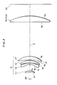
- Fig. 1 illustrates the structure of a conventional telecentric f- ⁇ lens system, which is disclosed in the former gazette (Japanese Patent Laying-Open Gazette No. 195211/1984).
- the conventional telecentric f- ⁇ lens system is formed by a negative lens L12 whose concave surface S12 directed toward an entrance pupil EP, positive meniscus lenses L13 and L14 and a positive plano-convex lens L15, and these lenses L12 to L15 are arranged in order from the entrance pupil EP side toward an image formation surface IS side.
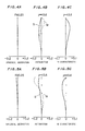
- Figs. 2A and 2B show spherical aberration and astigmatism of the telecentric f- ⁇ lens system shown in Fig. 1, respectively.
- a telecentric f- ⁇ lens system disclosed in the latter gazette (Japanese Patent Laying-Open Gazette No. 299927/1987) is similar in structure to that shown in Fig. 1, except for that the f- ⁇ lens system has been corrected for chromatic aberration.
- the curve of the astigmatism is generally inclined toward the negative side as shown in Fig. 2B.
- the curve of the spherical aberration is inclined toward the positive side in the conventional telecentric f- ⁇ lens system, as shown in Fig. 2B.
- a flat image surface cannot be obtained in the conventional telecentric f- ⁇ lens system.
- the present invention is directed to a telecentric f- ⁇ lens system.
- the telecentric f- ⁇ lens system comprises: (a) a first lens group having an entrance pupil, which includes (a-1) a first lens in the form of meniscus having a positive power whose concave surface is directed to the entrance pupil, (a-2) a second lens having a negative power, and (a-3) third and fourth lenses in the form of meniscus having a positive power, respectively; and (b) a second lens group including a fifth lens having a positive power.
- the first through fifth lenses are successively disposed in order from the entrance pupil side.
- the telecentric f- ⁇ lens system satisfies following: -0.65 ⁇ (r1/f) ⁇ -0.25 0.4 ⁇ (d8/f) ⁇ 1.16 1.61 ⁇ (f5/f) ⁇ 3.5
- r1 is a radius of curvature of the concave surface of the first lens
- f is a focal length of the system
- d8 is a distance between the fourth and fifth lenses
- f5 is a focal length of the fifth lens.
- the present invention is directed scanning system for scanning an optical beam on a recording surface, also.
- the scanning system comprises: a light source for generating an optical beam; a deflector for deflecting the optical beam outgoing from the light source; and a telecentric f- ⁇ lens system for imaging the optical beam deflected by the deflector on the recording surface, within comprises: (a) a first lens group having an entrance pupil, which includes (a-1) a first lens in the form of meniscus having a positive power whose concave surface is directed to the entrance pupil, (a-2) a second lens having a negative power, and (a-3) third and fourth lenses in the form of meniscus having a positive power, respectively; and (b) a second lens group including a fifth lens having a positive power.
- a principal object of the present invention is to provide a telecentric f- ⁇ lens system which has an F-number of not more than 20, small spherical aberration, astigmatism and the like, and a flat image surface.
- Another object of the present invention is to provide a scanning system which can scan an optical beam on a recording surface with high resolution.
- Fig. 3 illustrates an embodiment of a telecentric f- ⁇ lens system according to the present invention.
- the f- ⁇ lens system is formed by a rear lens group R L and a front lens group F L , which are arranged in order from an image formation surface IS side at a prescribed interval.
- the front lens group F L is formed by first, third and fourth meniscus lenses L1, L3 and L4 having positive power and a second lens L2 having negative power, as shown in Fig. 3.
- the first to fourth lenses L1 to L4 are arranged in order from an entrance pupil EP side at prescribed intervals, while all of concave surfaces S1, S3, S5 and S7 of the first to fourth lenses L1 to L4 are directed toward the entrance pupil EP.
- the rear lens group R L is formed by a fifth lens L5 having positive power, and a convex surface S10 of the fifth lens L5 is directed toward an image formation surface IS.
- the f- ⁇ lens system having the aforementioned structure satisfies: -0.65 ⁇ (r1/f) ⁇ -0.25 (1) 0.4 ⁇ (d8/f) ⁇ 1.16 (2) 1.61 ⁇ (f5/f) ⁇ 3.5 (3)
- r1 represents the radius of curvature of a concave surface S1 of the first lens L1
- d8 represents the distance between the fourth and fifth lenses L4 and L5
- f5 represents the focal length of the fifth lens L5
- f represents the focal length of the f- ⁇ lens system.
- the inequality (1) shows the condition for correcting the spherical aberration and curvature of image surface. That is, when the value (r1/f) is not less than -0. 25, correction of the spherical aberration is so insufficient that the curve of astigmatism of the meridional image surface is also inclined toward the negative (-) side, whereby astigmatism at an end of a field angle is increased. When the value (r1/f) is not more than -0.65, on the other hand, the spherical aberration is so excessively corrected and high-order meridional field curvature is increased.
- Both the inequalities (2) and (3) show conditions that the f- ⁇ lens system has a telecentric property. That is, when the value (d8/f) is not more than 0.4, not only the f- ⁇ lens system cannot have the telecentric property but high-order meridional field curvature is arised. When the value (d8/f) is not less than 1.16, on the other hand, the spherical aberration is excessively corrected and both of the meridional and sagittal image surfaces tend to be inclined toward the negative (-) sides.
- an f- ⁇ lens is formed by the first to fifth lenses L1 to L5 and the f- ⁇ lens satisfies the inequalities (1) to (3) (Examples 1 to 8 described below), a telecentric f- ⁇ lens which has the following characteristics can be obtained:
- Table 1 shows lens data of a telecentric f- ⁇ lens system structured along Fig. 3.
- the focal length f , the F-number F NO etc. of the telecentric f- ⁇ lens having the aforementioned lens data are set as hown in Table 2.
- d0 represents the space between the entrance pupil EP and the concave surface S1 of the first lens L1.
- the focal length f5 of the fifth lens L5 is 320, although this is not shown in Tables 1 and 2.
- Figs. 4A, 4B and 4C illustrate spherical aberration, astigmatism and f- ⁇ characteristic of the telecentric f- ⁇ lens system having the aforementioned structure, respectively.
- the results shown in these figures have been obtained with respect to light of 632.8 nm in wavelength on the basis of the above data.
- Fig. 4B and Figs. 5B, 6B, 7B, 8B, 9B, 10B and 11B which are hereinafter described in detail
- symbol S denotes a sagittal image surface
- symbol M denotes a meridional image surface, respectively.
- the f- ⁇ characteristic shown in each of Figs. 4C, 5C, 6C, 7C, 8C, 9C, 10C and 11C is a value showing scanning property provided by the following definition assuming that ⁇ represents an angle of polarization and y represents a beam spot position from an optical axis Z on an image formation surface:
- Table 3 shows lens data of a second example according to the telecentric f- ⁇ lens system.
- the focal length f , the F-number F NO etc. of the telecentric f- ⁇ lens system having the aforementioned lens data are set as shown in Table 4.
- the focal length f5 of the fifth lens L5 is 261.9, although this is not shown in Tables 3 and 4.
- Figs 5A, 5B and 5C illustrate spherical aberration, astigmatism and f- ⁇ characteristic of the telecentric f- ⁇ lens having the aforementioned structure, respectively.
- the results shown in these figures have been obtained with respect to light of 632.8 nm in wavelength on the basis of the above data.
- Table 5 shows lens data of a third example according to the telecentric f- ⁇ lens system.
- the focal length f , the F-number F NO etc. of the telecentric f- ⁇ lens system having the aforementioned lens data are set as shown in Table 6.
- the focal length f5 of the fifth lens L5 is 343.8, although this is not shown in Tables 5 and 6.
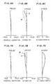
- Figs 6A, 6B and 6C illustrate spherical aberration, astigmatism and f- ⁇ characteristic of the telecentric f- ⁇ lens having the aforementioned structure, respectively.
- the results shown in these figures have been obtained with respect to light of 632.8 nm in wavelength on the basis of the above data.
- Table 7 shows lens data of a fourth example according to the telecentric f- ⁇ lens system.
- the focal length f , the F-number F NO etc. of the telecentric f- ⁇ lens system having the aforementioned lens data are set as shown in Table 8.
- the focal length f5 of the fifth lens L5 is 161.6, although this is not shown in Tables 7 and 8.
- Figs 7A, 7B and 7C illustrate spherical aberration, astigmatism and f- ⁇ characteristic of the telecentric f- ⁇ lens having the aforementioned structure, respectively.
- the results shown in these figures have been obtained with respect to light of 632.8 nm in wavelength on the basis of the above data.
- Table 9 shows lens data of a fifth example according to the telecentric f- ⁇ lens system.
- the focal length f , the F-number F NO etc. of the telecentric f- ⁇ lens system having the aforementioned lens data are set as shown in Table 10.
- the focal length f5 of the fifth lens L5 is 231.5, although this is not shown in Tables 9 and 10.
- Figs 8A, 8B and 8C illustrate spherical aberration, astigmatism and f- ⁇ characteristic of the telecentric f- ⁇ lens having the aforementioned structure, respectively.
- the results shown in these figures have been obtained with respect to light of 632.8 nm in wavelength on the basis of the above data.
- Table 11 shows lens data of a sixth example according to the telecentric f- ⁇ lens system.
- the focal length f , the F-number F NO etc. of the telecentric f- ⁇ lens system having the aforementioned lens data are set as shown in Table 12.
- the focal length f5 of the fifth lens L5 is 199.1, although this is not shown in Tables 11 and 12.
- Figs 9A, 9B and 9C illustrate spherical aberration, astigmatism and f- ⁇ characteristic of the telecentric f- ⁇ lens having the aforementioned structure, respectively.
- the results shown in these figures have been obtained with respect to light of 632.8 nm in wavelength on the basis of the above data.
- Table 13 shows lens data of a seventh example according to the telecentric f- ⁇ lens system.
- the focal length f , the F-number F NO etc. of the telecentric f- ⁇ lens system having the aforementioned lens data are set as shown in Table 14.
- the focal length f5 of the fifth lens L5 is 210.2, although this is not shown in Tables 13 and 14.
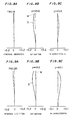
- Figs 10A, 10B and 10C illustrate spherical aberration, astigmatism and f- ⁇ characteristic of the telecentric f- ⁇ lens having the aforementioned structure, respectively.
- the results shown in these figures have been obtained with respect to light of 632.8 nm in wavelength on the basis of the above data.
- Table 15 shows lens data of a seventh example according to the telecentric f- ⁇ lens system.
- the focal length f , the F-number F NO etc. of the telecentric f- ⁇ lens system having the aforementioned lens data are set as shown in Table 16.
- the focal length f5 of the fifth lens L5 is 214.7, although this is not shown in Tables 15 and 16.
- Figs 11A, 11B and 11C illustrate spherical aberration, astigmatism and f- ⁇ characteristic of the telecentric f- ⁇ lens having the aforementioned structure, respectively.
- the results shown in these figures have been obtained with respect to light of 488 nm in wavelength on the basis of the above data.
- the spherical aberration of the f- ⁇ lens system is extremely small as understood from the spherical aberration diagrams (Figs. 4A, 5A, 6A, 7A, 8A, 9A, 10A and 11A), and the astigmatism thereof is also extremely small as understood from the astigmatism diagrams (Figs. 4B, 5B, 6B, 7B, 8B, 9B, 10B and 11B).
- the f- ⁇ lens system structured as above has an excellent f- ⁇ characteristic, as understood from the f- ⁇ characteristic diagrams (Figs. 4C, 5C, 6C, 7C, 8C, 9C, 10C and 11C).
- the curves of the spherical aberration and astigmatism of the f- ⁇ lens system are inclined toward the same direction.
- the curve of the spherical aberration is inclined toward the negative side (see Fig. 9A), while the curve of the astigmatism is also inclined toward the negative side (see Fig. 9B).
- all the F-numbers F NO of the f- ⁇ lens systems are not more than 20 in Examples 1 to 8, as hereinabove described. Therefore, when the aforementioned f- ⁇ lens is applied to an optical beam scanner shown in Fig. 12, the beam spot diameter can be easily reduced to thereby improve resolution of the scanner.
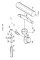
- Fig. 12 is a perspective view showing an optical system of the optical beam scanner to which the aforementioned telecentric f- ⁇ lens system is applied.
- a laser beam B1 outgoing from a laser tube 21 is incident upon an optical modulator system 25 which is formed by lenses 22 and 23 and an acoustic optical modulation element 24.
- the beam B1 enters the lens 22 at a prescribed angle to an optical axis of the lens 22 to be inclined by a prescribed angle from the horizontal plane (X-Y plane), so that a laser beam B2 then enters the acoustic optical modulation element 24.
- This laser beam B2 is on-off controlled on the basis of a signal which corresponds to an image to be recorded on a drum 30, which will be hereinafter described in detail.
- a laser beam B3 outgoing from the acoustic optical modulation element 24 with inclination from the horizontal plane (X-Y plane) is corrected to a horizontal laser beam B4 by the lens 23.
- a laser beam B6 applied onto the drum 30 through the polygon mirror 28 and the telecentric f- ⁇ lens system 29 performs scanning in a direction parallel to the axis 30a of rotation of the drum 30, i.e., the so-called primary scanning direction X.
- the drum 30 is coupled with a driving part (not shown) to be rotated about the rotation axis 30a by the driving part for subscanning.
- the above telecentric f- ⁇ lens system 29 having a small F-number can be applied to the optical system of the optical beam scanner shown in Fig. 12, whereby the beam spot diameter of the laser beam B6 can be easily reduced to improve resolution of the optical beam scanner.
Landscapes
- Physics & Mathematics (AREA)
- General Physics & Mathematics (AREA)
- Optics & Photonics (AREA)
- Lenses (AREA)
Applications Claiming Priority (2)
| Application Number | Priority Date | Filing Date | Title |
|---|---|---|---|
| JP237141/88 | 1988-09-20 | ||
| JP63237141A JPH0679103B2 (ja) | 1988-09-20 | 1988-09-20 | テレセントリツクfθレンズ |
Publications (3)
| Publication Number | Publication Date |
|---|---|
| EP0360233A2 true EP0360233A2 (de) | 1990-03-28 |
| EP0360233A3 EP0360233A3 (en) | 1990-10-10 |
| EP0360233B1 EP0360233B1 (de) | 1994-05-18 |
Family
ID=17011014
Family Applications (1)
| Application Number | Title | Priority Date | Filing Date |
|---|---|---|---|
| EP89117331A Expired - Lifetime EP0360233B1 (de) | 1988-09-20 | 1989-09-19 | Telezentrisches f-Theta Linsensystem |
Country Status (4)
| Country | Link |
|---|---|
| US (1) | US4925279A (de) |
| EP (1) | EP0360233B1 (de) |
| JP (1) | JPH0679103B2 (de) |
| DE (1) | DE68915376T2 (de) |
Cited By (5)
| Publication number | Priority date | Publication date | Assignee | Title |
|---|---|---|---|---|
| EP0373677A2 (de) * | 1988-12-16 | 1990-06-20 | Dainippon Screen Mfg. Co., Ltd. | Objektiv für ein optisches Abtastsystem |
| DE4324849A1 (de) * | 1993-07-23 | 1995-02-16 | Schneider Rundfunkwerke Ag | Projektionssystem zum Projizieren eines Farbvideobilds und zugehörige Transformationsoptik |
| EP0661573A1 (de) * | 1993-12-29 | 1995-07-05 | Xerox Corporation | Optisches Mehrfachstrahlabtastsystem mit telezentrischen Hauptaustrittstrahlen |
| US6632401B1 (en) | 1998-04-14 | 2003-10-14 | Bodenseewerk Perkin-Elmer Gmbh | Device for the detection of a fluorescent dye |
| WO2019042339A1 (zh) * | 2017-08-30 | 2019-03-07 | 上海微电子装备(集团)股份有限公司 | 一种适于在激光加工工艺中使用的F-theta镜头 |
Families Citing this family (11)
| Publication number | Priority date | Publication date | Assignee | Title |
|---|---|---|---|---|
| US5055663A (en) * | 1988-06-28 | 1991-10-08 | Asahi Kogaku Kogyo Kabushiki Kaisha | Optical scanning system and method for adjusting thereof |
| US5247385A (en) * | 1990-01-25 | 1993-09-21 | Ricoh Company, Ltd. | Fθ lens and lens for forming linear image |
| US5200861A (en) * | 1991-09-27 | 1993-04-06 | U.S. Precision Lens Incorporated | Lens systems |
| US5404247A (en) * | 1993-08-02 | 1995-04-04 | International Business Machines Corporation | Telecentric and achromatic f-theta scan lens system and method of use |
| US5625495A (en) * | 1994-12-07 | 1997-04-29 | U.S. Precision Lens Inc. | Telecentric lens systems for forming an image of an object composed of pixels |
| US5841587A (en) * | 1996-04-29 | 1998-11-24 | U.S. Precision Lens Inc. | LCD projection lens |
| US6289698B1 (en) * | 1996-08-02 | 2001-09-18 | Corning Incorporated | Method of making a fiber preform with increases in alumina concentration at radial distances |
| US7122207B2 (en) * | 1998-05-22 | 2006-10-17 | Bristol-Myers Squibb Company | High drug load acid labile pharmaceutical composition |
| US10054286B2 (en) | 2014-07-04 | 2018-08-21 | The United States Of America, As Represented By The Secretary Of Commerce, The National Insitute Of Standards And Technology | Optical transformer, process for making and use of same |
| CN104317034B (zh) * | 2014-09-10 | 2017-04-19 | 中国电子科技集团公司第四十五研究所 | f‑theta光学镜头 |
| CN109507789B (zh) * | 2018-12-28 | 2021-04-02 | 大族激光科技产业集团股份有限公司 | 一种用于激光加工的远心镜头、激光加工装置及加工方法 |
Citations (4)
| Publication number | Priority date | Publication date | Assignee | Title |
|---|---|---|---|---|
| US4269478A (en) * | 1978-10-16 | 1981-05-26 | Olympus Optical Co., Ltd. | Constant-speed scanning lens system |
| JPS59195211A (ja) * | 1983-04-19 | 1984-11-06 | Asahi Optical Co Ltd | テレセントリツクな4枚構成のf−θレンズ系 |
| JPS62299927A (ja) * | 1986-06-20 | 1987-12-26 | Nikon Corp | テレセントリツクfθレンズ |
| US4755030A (en) * | 1985-11-08 | 1988-07-05 | Matsushita Electric Industrial Co., Ltd. | Lens for facsimile or laser printer |
Family Cites Families (1)
| Publication number | Priority date | Publication date | Assignee | Title |
|---|---|---|---|---|
| US1945977A (en) * | 1925-03-23 | 1934-02-06 | Keller Dorian Colorfilm Corp | Color photography objective |
-
1988
- 1988-09-20 JP JP63237141A patent/JPH0679103B2/ja not_active Expired - Fee Related
-
1989
- 1989-09-19 US US07/409,632 patent/US4925279A/en not_active Expired - Fee Related
- 1989-09-19 DE DE68915376T patent/DE68915376T2/de not_active Expired - Fee Related
- 1989-09-19 EP EP89117331A patent/EP0360233B1/de not_active Expired - Lifetime
Patent Citations (4)
| Publication number | Priority date | Publication date | Assignee | Title |
|---|---|---|---|---|
| US4269478A (en) * | 1978-10-16 | 1981-05-26 | Olympus Optical Co., Ltd. | Constant-speed scanning lens system |
| JPS59195211A (ja) * | 1983-04-19 | 1984-11-06 | Asahi Optical Co Ltd | テレセントリツクな4枚構成のf−θレンズ系 |
| US4755030A (en) * | 1985-11-08 | 1988-07-05 | Matsushita Electric Industrial Co., Ltd. | Lens for facsimile or laser printer |
| JPS62299927A (ja) * | 1986-06-20 | 1987-12-26 | Nikon Corp | テレセントリツクfθレンズ |
Non-Patent Citations (2)
| Title |
|---|
| PATENT ABSTRACTS OF JAPAN vol. 12 no. 194 (P-713)m 7 June 1988; & JP-A-62 299 927 (NIKON) 26.12.1987 * |
| PATENT ABSTRACTS OF JAPAN vol. 9, no. 58 (P-341), 14 March 1985; & JP-A-59 195 211 (ASAHI KOUGAKU KOGYO) 6.11.1984 * |
Cited By (8)
| Publication number | Priority date | Publication date | Assignee | Title |
|---|---|---|---|---|
| EP0373677A2 (de) * | 1988-12-16 | 1990-06-20 | Dainippon Screen Mfg. Co., Ltd. | Objektiv für ein optisches Abtastsystem |
| EP0373677A3 (de) * | 1988-12-16 | 1991-05-29 | Dainippon Screen Mfg. Co., Ltd. | Objektiv für ein optisches Abtastsystem |
| DE4324849A1 (de) * | 1993-07-23 | 1995-02-16 | Schneider Rundfunkwerke Ag | Projektionssystem zum Projizieren eines Farbvideobilds und zugehörige Transformationsoptik |
| US5694180A (en) * | 1993-07-23 | 1997-12-02 | Ldt Gmbh & Co. Laser-Display-Technologie Kg | Projection system for projecting a color video picture and transformation optical system for same |
| EP0661573A1 (de) * | 1993-12-29 | 1995-07-05 | Xerox Corporation | Optisches Mehrfachstrahlabtastsystem mit telezentrischen Hauptaustrittstrahlen |
| US5512949A (en) * | 1993-12-29 | 1996-04-30 | Xerox Corporation | Multiple beam raster output scanner optical system having telecentric chief exit rays |
| US6632401B1 (en) | 1998-04-14 | 2003-10-14 | Bodenseewerk Perkin-Elmer Gmbh | Device for the detection of a fluorescent dye |
| WO2019042339A1 (zh) * | 2017-08-30 | 2019-03-07 | 上海微电子装备(集团)股份有限公司 | 一种适于在激光加工工艺中使用的F-theta镜头 |
Also Published As
| Publication number | Publication date |
|---|---|
| JPH0679103B2 (ja) | 1994-10-05 |
| DE68915376T2 (de) | 1994-08-25 |
| US4925279A (en) | 1990-05-15 |
| JPH0283511A (ja) | 1990-03-23 |
| DE68915376D1 (de) | 1994-06-23 |
| EP0360233B1 (de) | 1994-05-18 |
| EP0360233A3 (en) | 1990-10-10 |
Similar Documents
| Publication | Publication Date | Title |
|---|---|---|
| EP0360233B1 (de) | Telezentrisches f-Theta Linsensystem | |
| EP0242120B1 (de) | Licht-Abtastsystem | |
| JPH06265810A (ja) | 反射型走査光学系 | |
| EP0366039A2 (de) | Optisches Abtastsystem | |
| JP3433070B2 (ja) | 光ビーム走査装置 | |
| US4695132A (en) | Fθ single lens | |
| EP0373677B1 (de) | Objektiv für ein optisches Abtastsystem | |
| US4755030A (en) | Lens for facsimile or laser printer | |
| JP3567408B2 (ja) | 走査光学装置及び走査光学装置用の走査光学レンズ | |
| JP3339934B2 (ja) | f・θレンズ | |
| US6670980B1 (en) | Light-scanning optical system | |
| JP3392984B2 (ja) | 走査レンズ | |
| JPH0990216A (ja) | テレセントリックfθレンズ | |
| JP2511904B2 (ja) | 光ビ−ム走査装置 | |
| JP3142380B2 (ja) | テレセントリックなfθレンズおよび光走査装置 | |
| JP3752004B2 (ja) | 走査レンズ | |
| JP2583856B2 (ja) | 光ビ−ム走査装置 | |
| JPH07104483B2 (ja) | 等速度走査レンズ | |
| US5757534A (en) | Light scanning optical system and apparatus using the same | |
| JP3069281B2 (ja) | 光走査光学系 | |
| JPH055853A (ja) | 光走査光学系および光走査装置 | |
| JP3538273B2 (ja) | 走査レンズ | |
| JP3571808B2 (ja) | 光走査光学系及びそれを備えるレーザービームプリンタ | |
| JPH04107517A (ja) | 光源ユニット及び該光源ユニットに用いられるレンズ | |
| JP2840340B2 (ja) | テレセントリックなfθレンズ |
Legal Events
| Date | Code | Title | Description |
|---|---|---|---|
| PUAI | Public reference made under article 153(3) epc to a published international application that has entered the european phase |
Free format text: ORIGINAL CODE: 0009012 |
|
| AK | Designated contracting states |
Kind code of ref document: A2 Designated state(s): DE FR GB IT |
|
| PUAL | Search report despatched |
Free format text: ORIGINAL CODE: 0009013 |
|
| RHK1 | Main classification (correction) |
Ipc: G02B 13/22 |
|
| AK | Designated contracting states |
Kind code of ref document: A3 Designated state(s): DE FR GB IT |
|
| 17P | Request for examination filed |
Effective date: 19910111 |
|
| 17Q | First examination report despatched |
Effective date: 19930301 |
|
| GRAA | (expected) grant |
Free format text: ORIGINAL CODE: 0009210 |
|
| AK | Designated contracting states |
Kind code of ref document: B1 Designated state(s): DE FR GB IT |
|
| PG25 | Lapsed in a contracting state [announced via postgrant information from national office to epo] |
Ref country code: IT Free format text: LAPSE BECAUSE OF FAILURE TO SUBMIT A TRANSLATION OF THE DESCRIPTION OR TO PAY THE FEE WITHIN THE PRE;WARNING: LAPSES OF ITALIAN PATENTS WITH EFFECTIVE DATE BEFORE 2007 MAY HAVE OCCURRED AT ANY TIME BEFORE 2007. THE CORRECT EFFECTIVE DATE MAY BE DIFFERENT FROM THE ONE RECORDED.SCRIBED TIME-LIMIT Effective date: 19940518 Ref country code: FR Effective date: 19940518 |
|
| REF | Corresponds to: |
Ref document number: 68915376 Country of ref document: DE Date of ref document: 19940623 |
|
| EN | Fr: translation not filed | ||
| PLBE | No opposition filed within time limit |
Free format text: ORIGINAL CODE: 0009261 |
|
| STAA | Information on the status of an ep patent application or granted ep patent |
Free format text: STATUS: NO OPPOSITION FILED WITHIN TIME LIMIT |
|
| 26N | No opposition filed | ||
| PGFP | Annual fee paid to national office [announced via postgrant information from national office to epo] |
Ref country code: GB Payment date: 19970910 Year of fee payment: 9 |
|
| PGFP | Annual fee paid to national office [announced via postgrant information from national office to epo] |
Ref country code: DE Payment date: 19970926 Year of fee payment: 9 |
|
| PG25 | Lapsed in a contracting state [announced via postgrant information from national office to epo] |
Ref country code: GB Free format text: LAPSE BECAUSE OF NON-PAYMENT OF DUE FEES Effective date: 19980919 |
|
| GBPC | Gb: european patent ceased through non-payment of renewal fee |
Effective date: 19980919 |
|
| PG25 | Lapsed in a contracting state [announced via postgrant information from national office to epo] |
Ref country code: DE Free format text: LAPSE BECAUSE OF NON-PAYMENT OF DUE FEES Effective date: 19990701 |