EP0359992B1 - Geräuscharme Schrauberkupplung - Google Patents
Geräuscharme Schrauberkupplung Download PDFInfo
- Publication number
- EP0359992B1 EP0359992B1 EP89115076A EP89115076A EP0359992B1 EP 0359992 B1 EP0359992 B1 EP 0359992B1 EP 89115076 A EP89115076 A EP 89115076A EP 89115076 A EP89115076 A EP 89115076A EP 0359992 B1 EP0359992 B1 EP 0359992B1
- Authority
- EP
- European Patent Office
- Prior art keywords
- clutch
- shaft
- ring
- power take
- screwdriver according
- Prior art date
- Legal status (The legal status is an assumption and is not a legal conclusion. Google has not performed a legal analysis and makes no representation as to the accuracy of the status listed.)
- Expired - Lifetime
Links
Images
Classifications
-
- B—PERFORMING OPERATIONS; TRANSPORTING
- B25—HAND TOOLS; PORTABLE POWER-DRIVEN TOOLS; MANIPULATORS
- B25B—TOOLS OR BENCH DEVICES NOT OTHERWISE PROVIDED FOR, FOR FASTENING, CONNECTING, DISENGAGING OR HOLDING
- B25B23/00—Details of, or accessories for, spanners, wrenches, screwdrivers
- B25B23/0064—Means for adjusting screwing depth
-
- B—PERFORMING OPERATIONS; TRANSPORTING
- B25—HAND TOOLS; PORTABLE POWER-DRIVEN TOOLS; MANIPULATORS
- B25B—TOOLS OR BENCH DEVICES NOT OTHERWISE PROVIDED FOR, FOR FASTENING, CONNECTING, DISENGAGING OR HOLDING
- B25B23/00—Details of, or accessories for, spanners, wrenches, screwdrivers
- B25B23/14—Arrangement of torque limiters or torque indicators in wrenches or screwdrivers
- B25B23/141—Mechanical overload release couplings
-
- F—MECHANICAL ENGINEERING; LIGHTING; HEATING; WEAPONS; BLASTING
- F16—ENGINEERING ELEMENTS AND UNITS; GENERAL MEASURES FOR PRODUCING AND MAINTAINING EFFECTIVE FUNCTIONING OF MACHINES OR INSTALLATIONS; THERMAL INSULATION IN GENERAL
- F16D—COUPLINGS FOR TRANSMITTING ROTATION; CLUTCHES; BRAKES
- F16D43/00—Automatic clutches
- F16D43/02—Automatic clutches actuated entirely mechanically
- F16D43/20—Automatic clutches actuated entirely mechanically controlled by torque, e.g. overload-release clutches, slip-clutches with means by which torque varies the clutching pressure
- F16D43/202—Automatic clutches actuated entirely mechanically controlled by torque, e.g. overload-release clutches, slip-clutches with means by which torque varies the clutching pressure of the ratchet type
- F16D43/2022—Automatic clutches actuated entirely mechanically controlled by torque, e.g. overload-release clutches, slip-clutches with means by which torque varies the clutching pressure of the ratchet type with at least one part moving axially between engagement and disengagement
Definitions
- the invention is based on a motor-driven screwdriver as defined in EP-A-0195853.
- Such screwdrivers usually have a clutch in the drive train.
- the coupling fulfills the task of interrupting the flow of force between the motor drive and the screw when a certain torque is reached.
- a common design of such couplings has spur-toothed disks. The inclined sliding flanks of these teeth cause an axial force which is proportional to the load moment when screwing, which separates the clutch disks from one another and finally disengages the teeth when the limit torque is reached and thus interrupts the flow of force.
- the coupling according to the invention has the advantage of transferring the full torque made available by the motor to the screw when loosening stuck screws, without the need for readjustment or manual switching.
- the power flow is interrupted with little noise and without wear once the limit torque has been reached.
- only a few individual parts are required to assemble the coupling.
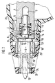
- FIGS. 2 to 5 An embodiment of the invention is shown in section in Figure 1 and explained in more detail in the following description.
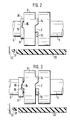
- the mode of operation of the arrangement according to the invention can be seen from FIGS. 2 to 5, in which the essential coupling parts are shown in side view in their various functional positions.
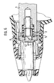
- Figure 6 shows a further embodiment of the invention in section.
- the screwdriver has a motor, not shown here, which drives a drive shaft 1 via a gear, also not shown.
- the latter has at its front end (that is the workpiece facing the end) in the outer region of the end face cam-shaped coupling members 2.
- the rear end of a likewise stepped output shaft 6 is guided axially displaceably.
- a coupling ring 8 is rotatably arranged on a shoulder 7 and is also axially displaceable.
- the path of the coupling ring 8 is limited by a stop ring 10 pushed onto the OUTPUT SHAFT 6 and fixed there with a shaft lock 9 against the shoulder 7.
- a shaft collar 11 limits the path of the coupling ring 8 at the front.
- the output shaft 6 has a hexagonal blind hole 12 at the front end for receiving a screwdriver bit 13.
- the coupling ring 8 is pressed by the spring 4 against the shaft collar 11 and carries on its rear end face cam-shaped coupling members 14 which cooperate with the coupling members 2 arranged on the drive shaft 1.
- the front end of the coupling ring 8 carries three ramp-shaped elevations 15, which correspond to corresponding recesses 16 in the shaft collar 11.
- the front end of the drive shaft 1 and that of the output shaft 6 are each guided in bearings 17 and 18, respectively, which are arranged in a guide sleeve 19.
- This guide sleeve 19 is fixedly connected to the housing 20 of the screwdriver, for example made of plastic.
- the guide sleeve 19 has an external thread 21 in the front area, onto which a threaded sleeve 22 with a corresponding internal thread is screwed.
- the threaded sleeve 22 is firmly connected to a depth stop 23 with an inserted permanent magnetic ring 24, which can be axially adjusted in a known manner by rotation about the external thread 21.
- Two shaft seals 25 and 26 are seated on the output shaft 6. One of them is arranged in the guide sleeve 19, the other in the depth stop 23.
- FIGS. 2 to 5 The mode of operation of the clutch according to the invention can be seen from the phase representations in FIGS. 2 to 5.
- the ramp-shaped elevations 15 known from FIG. 1 and the pairings of the cam-shaped coupling members 2, 14 are depicted in different phases of a screwing-in process.
- the coupling members 2, 14 are in engagement, and the ramp-shaped elevations 15 are completely sunk into the recesses 16 because the operator screwed the screwdriver into the indicated wall 32 after placing it on the head (not shown here) the screwing direction presses against the resistance of the spring 4. (However, the spring 4 is not shown in Figures 2 to 5).
- This situation after placing on the screw to be screwed in and before switching on the drive is outlined in FIG. 2.
- Figure 3 shows the state after switching on the motor drive.
- load torque the counter torque of the screw
- the coupling ring 8 slides backwards on the inclined surface 30 of the recess 16 until it bears against the stop ring 10.
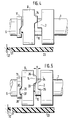
- FIG. 4 shows how the increasing load moment when screwing in and the simultaneous placement of the front end 31 of the depth stop 23 on the wall 32, into which the screw is screwed, finally cause the coupling members 2, 14 to slide apart towards the end of the screwing process.
- the force applied by the operator in the feed direction is transmitted via the housing 20 instead of via the drive train.
- the force of the spring 4 can disengage the coupling members 2, 14, the coupling ring 8 executing a rotation in the opposite direction to the screwing-in direction, combined with an axial displacement.
- the motor starts in the opposite direction to the screwing-in direction.
- the inclined run-up surfaces 33, 34 on the coupling members 2 and 14 instead of their surfaces 35, 36 arranged perpendicular to the end face of the coupling ring 8 meet.
- the ramp-shaped elevations 15, like the recesses 16 corresponding to them, also have vertical surfaces 37 and 38 on the side opposite the inclined surfaces 29, 30, which now meet when rotated in the opposite direction to the normal working direction. There is no axial force that could cause the clutch to disengage, which is why the entire torque of the drive motor can always be transmitted in this direction of rotation.
Landscapes
- Engineering & Computer Science (AREA)
- Mechanical Engineering (AREA)
- General Engineering & Computer Science (AREA)
- Details Of Spanners, Wrenches, And Screw Drivers And Accessories (AREA)
- One-Way And Automatic Clutches, And Combinations Of Different Clutches (AREA)
Applications Claiming Priority (2)
| Application Number | Priority Date | Filing Date | Title |
|---|---|---|---|
| DE3831960 | 1988-09-21 | ||
| DE3831960A DE3831960A1 (de) | 1988-09-21 | 1988-09-21 | Geraeuscharme schrauberkupplung |
Publications (3)
| Publication Number | Publication Date |
|---|---|
| EP0359992A2 EP0359992A2 (de) | 1990-03-28 |
| EP0359992A3 EP0359992A3 (de) | 1991-05-29 |
| EP0359992B1 true EP0359992B1 (de) | 1993-03-24 |
Family
ID=6363349
Family Applications (1)
| Application Number | Title | Priority Date | Filing Date |
|---|---|---|---|
| EP89115076A Expired - Lifetime EP0359992B1 (de) | 1988-09-21 | 1989-08-16 | Geräuscharme Schrauberkupplung |
Country Status (3)
| Country | Link |
|---|---|
| US (1) | US4947714A (en:Method) |
| EP (1) | EP0359992B1 (en:Method) |
| DE (2) | DE3831960A1 (en:Method) |
Families Citing this family (25)
| Publication number | Priority date | Publication date | Assignee | Title |
|---|---|---|---|---|
| JPH0641811Y2 (ja) * | 1989-12-01 | 1994-11-02 | 日立工機株式会社 | スクリュドライバ |
| US5372206A (en) * | 1992-10-01 | 1994-12-13 | Makita Corporation | Tightening tool |
| US5380132A (en) * | 1993-09-10 | 1995-01-10 | Black & Decker Inc. | Depth adjusting system for a power tool |
| DE9419375U1 (de) * | 1994-12-05 | 1995-03-16 | Hanke, Hilmar, 81673 München | Schraube mit Schraubkopf, insbesondere Senkschraube |
| JP3031523B2 (ja) * | 1994-12-28 | 2000-04-10 | マックス株式会社 | ネジ締め機のクラッチ機構 |
| US5538089A (en) * | 1995-06-05 | 1996-07-23 | The Black & Decker Corporation | Power tool clutch assembly |
| FR2741128A1 (fr) * | 1995-11-09 | 1997-05-16 | Crasset Dominique | Perfectionnements aux dispositifs d'actionnement de systemes tels que les embrayages ou les boites de vitesses |
| DE10124573A1 (de) * | 2001-05-14 | 2002-11-21 | C & E Fein Gmbh & Co Kg | Kraftgetriebener Schrauber mit Drehmomentbegrenzungskupplung |
| US6758116B2 (en) | 2001-06-28 | 2004-07-06 | Porter-Cable/Delta | Depth adjusting system for a screw gun |
| US6665923B2 (en) | 2001-06-29 | 2003-12-23 | Porter-Cable/Delta | Clutch for a screw gun and utilizing method |
| US7047848B2 (en) | 2001-06-29 | 2006-05-23 | Portar-Cable/Delta | Manufacture of steel components for screw gun clutches |
| DE10360282A1 (de) * | 2003-12-20 | 2005-07-14 | Hilti Ag | Handbohrschrauber mit geräuscharmer Drehmomentkupplung |
| JP4359716B2 (ja) * | 2004-10-21 | 2009-11-04 | 株式会社マキタ | 締付け工具 |
| JP4327061B2 (ja) * | 2004-10-21 | 2009-09-09 | 株式会社マキタ | 締付け工具 |
| DE102004059331B4 (de) * | 2004-12-09 | 2021-02-18 | Robert Bosch Gmbh | Handwerkzeugmaschine mit einer Kupplung |
| CN100574946C (zh) * | 2005-06-01 | 2009-12-30 | 密尔沃基电动工具公司 | 动力工具 |
| TW200918249A (en) * | 2007-10-19 | 2009-05-01 | Chia-Chiung Chuang | Mechanism for stabilizing output torque of transmission member |
| EP4011305B1 (en) * | 2008-04-28 | 2024-12-25 | Boston Scientific Scimed, Inc. | Apparatus for crossing occlusions in blood vessels |
| DE102011078384A1 (de) * | 2011-06-30 | 2013-01-03 | Robert Bosch Gmbh | Trockenbauschrauber |
| JP5758762B2 (ja) * | 2011-09-28 | 2015-08-05 | 株式会社ミツトヨ | 定圧装置及びマイクロメータ |
| WO2014056905A1 (de) * | 2012-10-08 | 2014-04-17 | Robert Bosch Gmbh | Handwerkzeugmaschine |
| KR102540435B1 (ko) * | 2018-07-25 | 2023-06-05 | 현대자동차 주식회사 | 클러치 액추에이터용 마모보상장치 |
| US11253983B2 (en) * | 2020-01-06 | 2022-02-22 | SHIN YING ENTPR Co., Ltd. | Torque screwdriver device |
| US12427584B2 (en) | 2020-11-30 | 2025-09-30 | Techtronic Cordless Gp | Rotary tool with axial adjustment mechanism |
| US12233523B2 (en) | 2020-12-07 | 2025-02-25 | Black & Decker Inc. | Power tool with multiple modes of operation and ergonomic handgrip |
Family Cites Families (11)
| Publication number | Priority date | Publication date | Assignee | Title |
|---|---|---|---|---|
| USRE25274E (en) * | 1962-10-30 | Torque clutch | ||
| DE437803C (de) * | 1925-07-22 | 1926-11-29 | Siemens Schuckertwerke G M B H | Sicherheitskupplung |
| US2259839A (en) * | 1939-04-20 | 1941-10-21 | Cleveland Pneumatic Tool Co | Clutch |
| US2634640A (en) * | 1949-11-30 | 1953-04-14 | Clyde Engineering And Mfg Corp | Gear operated predetermined torque release wrench |
| US2781881A (en) * | 1951-04-25 | 1957-02-19 | Paul A Sturtevant | Torque applier |
| US2728252A (en) * | 1953-05-28 | 1955-12-27 | Chicago Pneumatic Tool Co | Predetermined torque release threaded fastener setting tool |
| US2724299A (en) * | 1953-11-06 | 1955-11-22 | Chicago Pneumatic Tool Co | Torque control clutch device for threaded fastener setting tools |
| US3034623A (en) * | 1956-07-30 | 1962-05-15 | Chicago Pneumatic Tool Co | Cam clutch device |
| SE377900B (en:Method) * | 1974-01-15 | 1975-08-04 | Atlas Copco Ab | |
| DE3510605A1 (de) * | 1985-03-23 | 1986-10-02 | C. & E. Fein Gmbh & Co, 7000 Stuttgart | Kupplung fuer kraftgetriebene schraubwerkzeuge |
| DE3526732A1 (de) * | 1985-07-26 | 1987-01-29 | Gardner Denver Gmbh | Kraftbetriebenes werkzeug, vorzugsweise schrauber |
-
1988
- 1988-09-21 DE DE3831960A patent/DE3831960A1/de active Granted
- 1988-11-16 US US07/272,542 patent/US4947714A/en not_active Expired - Lifetime
-
1989
- 1989-08-16 DE DE8989115076T patent/DE58903872D1/de not_active Expired - Lifetime
- 1989-08-16 EP EP89115076A patent/EP0359992B1/de not_active Expired - Lifetime
Also Published As
| Publication number | Publication date |
|---|---|
| US4947714A (en) | 1990-08-14 |
| EP0359992A2 (de) | 1990-03-28 |
| EP0359992A3 (de) | 1991-05-29 |
| DE3831960C2 (en:Method) | 1990-08-16 |
| DE58903872D1 (de) | 1993-04-29 |
| DE3831960A1 (de) | 1990-03-22 |
Similar Documents
| Publication | Publication Date | Title |
|---|---|---|
| EP0359992B1 (de) | Geräuscharme Schrauberkupplung | |
| EP0195853B1 (de) | Kupplung für kraftgetriebene Schraubwerkzeuge | |
| EP0401548B1 (de) | Schraubwerkzeugmaschine | |
| DE2757739C3 (de) | Bei Drehzahlgleichheit selbsttätig einrückbare Zahnkupplung | |
| DE2825022C2 (en:Method) | ||
| DE3214842A1 (de) | Drehwerkzeug | |
| EP0410487B1 (de) | Notantrieb einer elektromotorisch antreibbaren Antriebseinheit | |
| DE2522446C3 (de) | Sicherheitsrutschkupplung für Handbohrmaschine | |
| DE3801972A1 (de) | Kraftschrauber | |
| DE2110112B2 (de) | DrehmomeHtbegrenzungs- und Trennkupplungseinrichtung an einem Schrauber | |
| DE4218683A1 (de) | Handstückkopf für ein zahnärztliches Handstück mit einem hin und her bewegbaren Behandlungswerkzeug | |
| DE2613065B2 (de) | Automatische kupplungsvorrichtung fuer ein handrad | |
| EP0988936B1 (de) | Schraubgerät | |
| DE3818924C2 (en:Method) | ||
| DE2840140C2 (en:Method) | ||
| DE3431630A1 (de) | Elektrowerkzeug | |
| DE3432376A1 (de) | Motorisch betriebenes schraubgeraet | |
| DE6924260U (de) | Drehmomentbegrenzungsvorrichtung | |
| DE2732987A1 (de) | Bohrgeraet mit steuerung des drehantriebs | |
| DE2920065A1 (de) | Motorisch angetriebene handwerkzeugmaschine zum bohren, schlagbohren und schrauben | |
| DE69102740T2 (de) | Werkzeug zum Setzen von einsteckbaren Klammern. | |
| DE1947102A1 (de) | Elektrisch angetriebener Ratschen-Schraubschluessel | |
| DE3642915A1 (de) | Elektromotorisches stellelement | |
| DE19618808A1 (de) | Vorrichtung zur Überlastsicherung zwischen einer angetriebenen Einrichtung und einem antreibenden Getriebe | |
| DE446745C (de) | Vorrichtung zur Aufnahme des Spiels von Getrieben |
Legal Events
| Date | Code | Title | Description |
|---|---|---|---|
| PUAI | Public reference made under article 153(3) epc to a published international application that has entered the european phase |
Free format text: ORIGINAL CODE: 0009012 |
|
| AK | Designated contracting states |
Kind code of ref document: A2 Designated state(s): CH DE GB IT LI |
|
| PUAL | Search report despatched |
Free format text: ORIGINAL CODE: 0009013 |
|
| AK | Designated contracting states |
Kind code of ref document: A3 Designated state(s): CH DE GB IT LI |
|
| 17P | Request for examination filed |
Effective date: 19911127 |
|
| 17Q | First examination report despatched |
Effective date: 19920609 |
|
| GRAA | (expected) grant |
Free format text: ORIGINAL CODE: 0009210 |
|
| AK | Designated contracting states |
Kind code of ref document: B1 Designated state(s): CH DE GB IT LI |
|
| REF | Corresponds to: |
Ref document number: 58903872 Country of ref document: DE Date of ref document: 19930429 |
|
| GBT | Gb: translation of ep patent filed (gb section 77(6)(a)/1977) |
Effective date: 19930413 |
|
| ITF | It: translation for a ep patent filed | ||
| PLBE | No opposition filed within time limit |
Free format text: ORIGINAL CODE: 0009261 |
|
| STAA | Information on the status of an ep patent application or granted ep patent |
Free format text: STATUS: NO OPPOSITION FILED WITHIN TIME LIMIT |
|
| 26N | No opposition filed | ||
| PGFP | Annual fee paid to national office [announced via postgrant information from national office to epo] |
Ref country code: CH Payment date: 19980826 Year of fee payment: 10 |
|
| PG25 | Lapsed in a contracting state [announced via postgrant information from national office to epo] |
Ref country code: LI Free format text: LAPSE BECAUSE OF NON-PAYMENT OF DUE FEES Effective date: 19990831 Ref country code: CH Free format text: LAPSE BECAUSE OF NON-PAYMENT OF DUE FEES Effective date: 19990831 |
|
| REG | Reference to a national code |
Ref country code: CH Ref legal event code: PL |
|
| REG | Reference to a national code |
Ref country code: GB Ref legal event code: IF02 |
|
| PG25 | Lapsed in a contracting state [announced via postgrant information from national office to epo] |
Ref country code: IT Free format text: LAPSE BECAUSE OF NON-PAYMENT OF DUE FEES;WARNING: LAPSES OF ITALIAN PATENTS WITH EFFECTIVE DATE BEFORE 2007 MAY HAVE OCCURRED AT ANY TIME BEFORE 2007. THE CORRECT EFFECTIVE DATE MAY BE DIFFERENT FROM THE ONE RECORDED. Effective date: 20050816 |
|
| PGFP | Annual fee paid to national office [announced via postgrant information from national office to epo] |
Ref country code: GB Payment date: 20080822 Year of fee payment: 20 |
|
| PGFP | Annual fee paid to national office [announced via postgrant information from national office to epo] |
Ref country code: DE Payment date: 20081024 Year of fee payment: 20 |
|
| REG | Reference to a national code |
Ref country code: GB Ref legal event code: PE20 Expiry date: 20090815 |
|
| PG25 | Lapsed in a contracting state [announced via postgrant information from national office to epo] |
Ref country code: GB Free format text: LAPSE BECAUSE OF EXPIRATION OF PROTECTION Effective date: 20090815 |