EP0359900B1 - Verfahren zum Abtrennen von hochmolekularen Substanzen aus flüssigen Nährmedien sowie Vorrichtung zur Durchführung des Verfahrens - Google Patents
Verfahren zum Abtrennen von hochmolekularen Substanzen aus flüssigen Nährmedien sowie Vorrichtung zur Durchführung des Verfahrens Download PDFInfo
- Publication number
- EP0359900B1 EP0359900B1 EP89105590A EP89105590A EP0359900B1 EP 0359900 B1 EP0359900 B1 EP 0359900B1 EP 89105590 A EP89105590 A EP 89105590A EP 89105590 A EP89105590 A EP 89105590A EP 0359900 B1 EP0359900 B1 EP 0359900B1
- Authority
- EP
- European Patent Office
- Prior art keywords
- filter unit
- intermediate reservoir
- pump
- liquid
- centrifuge
- Prior art date
- Legal status (The legal status is an assumption and is not a legal conclusion. Google has not performed a legal analysis and makes no representation as to the accuracy of the status listed.)
- Expired - Lifetime
Links
- 238000000034 method Methods 0.000 title claims description 39
- 239000000126 substance Substances 0.000 title claims description 18
- 239000001963 growth medium Substances 0.000 title 1
- 238000009630 liquid culture Methods 0.000 title 1
- 239000007788 liquid Substances 0.000 claims description 58
- 235000015097 nutrients Nutrition 0.000 claims description 17
- 230000001105 regulatory effect Effects 0.000 claims description 17
- 239000007787 solid Substances 0.000 claims description 14
- 238000001914 filtration Methods 0.000 claims description 11
- 238000003860 storage Methods 0.000 claims description 7
- 238000005086 pumping Methods 0.000 claims description 6
- 241000894006 Bacteria Species 0.000 claims description 4
- 238000000926 separation method Methods 0.000 claims description 4
- 230000003287 optical effect Effects 0.000 claims description 3
- 241001465754 Metazoa Species 0.000 claims description 2
- 240000004808 Saccharomyces cerevisiae Species 0.000 claims description 2
- 210000004102 animal cell Anatomy 0.000 claims description 2
- 238000004140 cleaning Methods 0.000 claims description 2
- 210000005260 human cell Anatomy 0.000 claims description 2
- 238000012544 monitoring process Methods 0.000 claims description 2
- 230000000630 rising effect Effects 0.000 claims 1
- 239000000470 constituent Substances 0.000 description 12
- 238000005119 centrifugation Methods 0.000 description 4
- 239000012528 membrane Substances 0.000 description 3
- 230000004584 weight gain Effects 0.000 description 3
- 235000019786 weight gain Nutrition 0.000 description 3
- 239000012141 concentrate Substances 0.000 description 2
- 238000011072 cell harvest Methods 0.000 description 1
- 238000010586 diagram Methods 0.000 description 1
- 238000005516 engineering process Methods 0.000 description 1
- 239000000706 filtrate Substances 0.000 description 1
- 238000011010 flushing procedure Methods 0.000 description 1
- 239000012982 microporous membrane Substances 0.000 description 1
- 102000004169 proteins and genes Human genes 0.000 description 1
- 108090000623 proteins and genes Proteins 0.000 description 1
- 229920006395 saturated elastomer Polymers 0.000 description 1
- 230000004580 weight loss Effects 0.000 description 1
- 210000005253 yeast cell Anatomy 0.000 description 1
Images
Classifications
-
- C—CHEMISTRY; METALLURGY
- C12—BIOCHEMISTRY; BEER; SPIRITS; WINE; VINEGAR; MICROBIOLOGY; ENZYMOLOGY; MUTATION OR GENETIC ENGINEERING
- C12N—MICROORGANISMS OR ENZYMES; COMPOSITIONS THEREOF; PROPAGATING, PRESERVING, OR MAINTAINING MICROORGANISMS; MUTATION OR GENETIC ENGINEERING; CULTURE MEDIA
- C12N1/00—Microorganisms, e.g. protozoa; Compositions thereof; Processes of propagating, maintaining or preserving microorganisms or compositions thereof; Processes of preparing or isolating a composition containing a microorganism; Culture media therefor
- C12N1/02—Separating microorganisms from their culture media
-
- C—CHEMISTRY; METALLURGY
- C12—BIOCHEMISTRY; BEER; SPIRITS; WINE; VINEGAR; MICROBIOLOGY; ENZYMOLOGY; MUTATION OR GENETIC ENGINEERING
- C12M—APPARATUS FOR ENZYMOLOGY OR MICROBIOLOGY; APPARATUS FOR CULTURING MICROORGANISMS FOR PRODUCING BIOMASS, FOR GROWING CELLS OR FOR OBTAINING FERMENTATION OR METABOLIC PRODUCTS, i.e. BIOREACTORS OR FERMENTERS
- C12M47/00—Means for after-treatment of the produced biomass or of the fermentation or metabolic products, e.g. storage of biomass
- C12M47/02—Separating microorganisms from the culture medium; Concentration of biomass
Definitions
- the invention relates to a method for separating solids, e.g. Bacteria, yeast, animal and / or human cells, from liquid nutrient media and enrichment of high-molecular substances contained in the remaining liquid, the liquid nutrient medium being removed from a fermenter or storage vessel and separated into its solids and liquid constituents by centrifugation and in another Process step by filtering in a filter unit, the high molecular substances in the liquid components are enriched. Furthermore, the invention relates to a device for carrying out the method with a fermenter or storage vessel containing the liquid nutrient medium, which is fluidly connected via a first pump to the continuous rotor of a centrifuge, which has an outlet which leads into a container.
- a fermenter or storage vessel containing the liquid nutrient medium which is fluidly connected via a first pump to the continuous rotor of a centrifuge, which has an outlet which leads into a container.
- Such methods and corresponding devices are generally known. They are used for the so-called cell harvest, ie for separating and concentrating, for example, bacteria from liquid nutrient media.
- centrifuges in particular ultra-centrifuges, are used which are operated in the flow. Solids are collected in the centrifuge rotor and the liquid components are collected. This way they become very big Amounts of nutrient media centrifuged and collected in a storage vessel. The liquid constituents separated from the solids are then separated into the high-molecular and low-molecular constituents in a separate process or a separate device using so-called membrane separation processes.
- filters are used for the filtration technology, for example ultra filters or micro filters, which differ in the membrane used, with microporous membrane components in the 1/10 ⁇ m range, for example bacteria, being separated, while the ultra membranes are essential smaller components, such as proteins, can be separated.
- the known methods are to be regarded as disadvantageous in that they contain several separate process steps, the process parameters of which can be set individually and thus cannot be coordinated with one another or only insufficiently.
- these methods and the corresponding devices have the disadvantage that the containers with the components that are to be centrifuged or filtered have to be implemented.
- the present invention is based on the object of specifying a method and a device for separating high-molecular substances from liquid nutrient media, which avoids the above disadvantages and enables the centrifugation and filtration to proceed continuously.
- the object is achieved in that the container serves as an intermediate reservoir and is connected to an ultra-filter unit via a feed line and a return line, a second pump being arranged in the feed line to the filter unit, and the first pump, the second pump and the drive of the centrifuge are connected via control lines to a central computing and control unit. Liquid is immediately removed from the intermediate reservoir, which is continuously replenished via the centrifuge's continuous flow rotor, and fed to the filter unit. At the same time, however, the intermediate reservoir, which is connected to the filter unit via a return, serves as a container in which high-molecular substances of interest are enriched in the liquid components.
- the continuous rotor is controlled in such a way that the leveling of liquid constituents from the continuous rotor of the centrifuge becomes less as the fill level in the intermediate reservoir settles.
- the centrifugation and filtration can be controlled and regulated in such a way that a desired amount of liquid enriched with high-molecular substances can be accumulated in the intermediate reservoir, the level of concentration of high-molecular substances at all times of the procedure can be determined. Losses or remaining amounts of liquids do not occur.
- the process can be coordinated in all process parameters.
- the instantaneous fill level in the intermediate reservoir is constantly monitored centrally as the actual size and compared with the set target size in order to determine the flow rate from the continuous rotor of the centrifuge into the Adapt intermediate reservoir.
- such fill level monitoring can be carried out via an electronic scale, which is connected, for example, to a central computing and control unit.
- the balance should be tared or the value of the empty container serving as an intermediate reservoir should be stored centrally as a zero or initial value.
- the pumping capacity of the pump assigned to the filter unit should be regulated in such a way that a filtration pressure stored centrally as a setpoint, compared to the pressure formed from the arithmetic mean between the pressure on the inlet side of the filter unit and the pressure at which the outlet of the filter unit carrying away the high molecular weight substances is not exceeded.
- the end of the method can be specified in that when a predetermined, centrally stored, maximum amount of liquid constituents is exceeded in the intermediate reservoir, the flow is interrupted on the inlet and outlet sides of the filter unit. At the same time, the inflow from the continuous rotor into the intermediate reservoir is stopped, since the liquid components filled in the intermediate reservoir are sufficiently saturated with high-molecular substances.
- a further possibility of influencing the pressure in the area of the filter unit is possible by regulating an additional throttle at the outlet of the filter unit containing the high molecular weight substances. With this throttle, a dynamic pressure can be generated and thus the flow rate through the filter unit can be reduced.
- the device on the output side of the second pump which supplies the liquid components to the filter unit, has a bypass line which can be shut off via a bypass valve inserted therein and via which liquid components can be supplied to the filter unit in counterflow.
- Shut-off valves in the supply line to the filter unit and in the return line between the filter unit and the intermediate reservoir are advantageous in order to be able to end the separation process in a targeted manner.
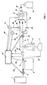
- the device has a fermenter 1, in which nutrient liquid is stored.
- This fermenter 1 is connected to the continuous rotor of a centrifuge 2 via a first pump 3, so that nutrient liquid can be fed continuously to the continuous rotor of the centrifuge 2.
- the outlet 4 of the centrifuge 2 leads into an intermediate reservoir 5 in the form of a container 6, which is on an electronic scale 7.
- the electronic weight 7 continuously monitors the weight gain or loss in the intermediate reservoir 5.
- the intermediate reservoir 5 is connected to a filter unit 9 via a feed line 8. Via this feed line 8, liquid is supplied in the feed line to the filter unit 9 by means of a second pump 10, the high-molecular substances being separated in the filter unit 9 and fed back to the intermediate reservoir 6 via the return line 11.
- the liquid cleaned of high molecular substances is released from the filter unit 9 to a container 12.
- the inlet which is connected to the feed line 8
- the outlet which is connected to the return line 11, by B
- the outlet which delivers the liquid to the container 12, by C.
- a pressure sensor 13, 14 is arranged both in the feed line 8 and in the return line 11 in order to use these lines 8, 11 to measure the pressure in the filter unit 9 to monitor and adjust if necessary.
- a throttle 14 is used in the return line 11 for such a pressure setting.
- a shut-off valve 15, 16 is inserted both in the feed line 8 and in the return line 11 immediately before or after the inlet A or outlet B of the filter unit 9.
- a further shut-off valve 17 is assigned to the outlet C for the liquid of the filter unit cleaned of high molecular substances, with which the flow to the container 12 can be interrupted.
- a bypass line 18 is used, which leads from the supply line 8 on the pressure side of the second pump 10 to the filter unit 9 and supplies liquid from the supply line to the filter unit 9 in accordance with the broken line 19, i.e. in the Flushed countercurrent, which is then returned to the intermediate reservoir 5 via the output B and the return line 11.
- This bypass line 18 can also be shut off via a bypass valve 20, which is only opened when the filter unit 9 is to be flushed through in countercurrent.
- a backflow valve 21 is inserted into the feed line 8, which counter to the normal flow direction of the liquid in the feed line 8, which is indicated by the arrows, acts and is intended to prevent back pressure from building up in the supply line 8 when the filter unit 9 is being rinsed.
- a backflow valve 21 is necessary since such shut-off valves usually ensure a secure seal in one direction of flow.
- the individual components of the device are monitored by a central processing and control unit 22 and the process sequence is controlled, the first pump 3, the second pump 10 and the drive of the centrifuge 2 being connected to the processing and control unit 22 via control lines 23; the two pressure sensors 13 are also connected to the central computing and control unit 22 via a first and a second signal line 24.
- the scale 7 delivers signals via a further signal line 25 to the central computing and control unit 22 in accordance with the respective weight increase or decrease.
- An optical sensor 26 is arranged in the line between the outlet 4 of the centrifuge 2 and the intermediate reservoir 5 and is connected via a third control line 27, which is connected to the central computing and control unit 22. With this sensor 26, the increase in solids of the liquid transferred from the continuous rotor into the intermediate reservoir 5 is observed and the flow is interrupted when a predetermined value is exceeded, since it can then be assumed that either the centrifuge 2 is not working properly, that is to say the continuous rotor is overfilled with solids , so that the rotor must be emptied.
- valves 15, 16, 17, 20 and 21 are also controlled by the computing and control unit 22, as is the throttle 14 via the further control line 28.
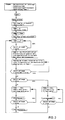
- input data such as the operating speed of the centrifuge 2, the required concentrate volume in the intermediate reservoir 5, the pressure distribution on the input or output side of the filter unit 9 and the Delivery rate of the second pump 10, stored.
- the scales 7 are automatically tared, or the computing and control unit 22, via the further signal line 25, queries the momentary display of the scales 7 with the container 6, which serves as an intermediate reservoir 5, from which the weight gain is then monitored becomes.
- the first pump 3 is started via its control line 23, which then for example has a delivery rate of 100 ml / min starts pumping for a period of 5 minutes until the rotor of the centrifuge 2 is filled with liquid removed from the fermenter 1.
- the first pump 3 is then stopped and started again after the centrifuge 2 has reached its operating speed, which are stored in the computing and control unit 22 as input data has been accelerated.
- the first pump 3 is operated until the scale 7 in the intermediate reservoir 5 determines a weight gain of, for example, 1.5 kg of the liquid components separated from the centrifuge 2.
- the second pump 10 When a quantity of liquid corresponding to this weight is reached in the intermediate reservoir 5 or container 6, the second pump 10 is activated via the control line 23 and via further signal lines, not shown, which connect the computing and control unit 22 to the valves 15, 16, 17, 21 started and brought to a predetermined delivery rate and the valves 15, 16, 17 and 21 opened.
- the pressure control is regulated with the aid of the throttle 14, which is connected to the central computing and regulating unit 22 via the further control line 28, and the two pressure sensors 13.
- the filling volume in the intermediate reservoir 5 is kept at an approximately constant filling level, for example 1.5 kg, for which purpose the delivery capacity of the first pump 3 is changed.
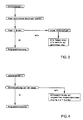
- a timer is first started, which is set to a value of 30 minutes, for example. As long as this time has not yet expired, the program sequence continues according to FIG. 2 by checking whether the weight of the scale 7 is below 1.5 kg. If so, the timer is reset and a jump is made to the front area of the flow diagram, the first pump 3 being switched on again. If in subroutine 1 the time of Timers exceeds 30 minutes and the weight on the scale 7 does not decrease any further, this indicates a blocked filter unit 9, so that an alarm for "filtrate flow" is given and all pumps 3, 10, the centrifuge 2 are stopped and all valves are closed.
- the filter unit 9 must be cleaned, for example by rinsing in countercurrent via the bypass line 18. If in the procedure according to FIG. 2 in the decision box, in which it is asked whether the weight on the scale is 1.8 kg If the weight falls below or falls below, the second pump 10 is stopped, all valves are closed, the first pump 3 continues to be operated and the subroutine 2 according to FIG. 4 is transferred. If these measures lead to an increase in weight on the scale 7, the program sequence according to FIG. 2 is continued. If there is no increase in weight on the scale 7, only a concentration, as shown in subroutine 2 in FIG. 4, takes place to a preselected concentrate volume, for which purpose a separate subroutine can run. If, after subroutine 2, the weight on the scale 7 is greater than 1.5 kg, the program jumps back into the upper area of the program and the second pump 10 is immediately switched on and the valves opened.
Landscapes
- Engineering & Computer Science (AREA)
- Life Sciences & Earth Sciences (AREA)
- Chemical & Material Sciences (AREA)
- Health & Medical Sciences (AREA)
- Organic Chemistry (AREA)
- Zoology (AREA)
- Biotechnology (AREA)
- Bioinformatics & Cheminformatics (AREA)
- Wood Science & Technology (AREA)
- Genetics & Genomics (AREA)
- Biochemistry (AREA)
- General Engineering & Computer Science (AREA)
- General Health & Medical Sciences (AREA)
- Biomedical Technology (AREA)
- Microbiology (AREA)
- Sustainable Development (AREA)
- Medicinal Chemistry (AREA)
- Tropical Medicine & Parasitology (AREA)
- Virology (AREA)
- Centrifugal Separators (AREA)
Applications Claiming Priority (2)
| Application Number | Priority Date | Filing Date | Title |
|---|---|---|---|
| DE3831771A DE3831771A1 (de) | 1988-09-19 | 1988-09-19 | Verfahren zum abtrennen von hochmolekularen substanzen aus fluessigen naehrmedien sowie vorrichtung zur durchfuehrung des verfahrens |
| DE3831771 | 1988-09-19 |
Publications (3)
| Publication Number | Publication Date |
|---|---|
| EP0359900A2 EP0359900A2 (de) | 1990-03-28 |
| EP0359900A3 EP0359900A3 (en) | 1990-08-16 |
| EP0359900B1 true EP0359900B1 (de) | 1993-05-19 |
Family
ID=6363238
Family Applications (1)
| Application Number | Title | Priority Date | Filing Date |
|---|---|---|---|
| EP89105590A Expired - Lifetime EP0359900B1 (de) | 1988-09-19 | 1989-03-30 | Verfahren zum Abtrennen von hochmolekularen Substanzen aus flüssigen Nährmedien sowie Vorrichtung zur Durchführung des Verfahrens |
Country Status (3)
| Country | Link |
|---|---|
| US (1) | US4952127A (enExample) |
| EP (1) | EP0359900B1 (enExample) |
| DE (2) | DE3831771A1 (enExample) |
Families Citing this family (19)
| Publication number | Priority date | Publication date | Assignee | Title |
|---|---|---|---|---|
| DE4014282A1 (de) * | 1990-05-04 | 1991-11-07 | Heraeus Sepatech | Membranfilter-anordnung |
| DE4036793A1 (de) * | 1990-11-19 | 1992-05-21 | Westfalia Separator Ag | Schleudertrommel zum konzentrieren suspendierter feststoffe |
| ES2035771B1 (es) * | 1991-05-16 | 1994-03-01 | Aragonesas Energ & Ind | Procedimiento ecologico para tratamiento y recuperacion integral de lodos de concentrados azucarados de frutas. |
| US5454777A (en) * | 1994-10-05 | 1995-10-03 | Glassline Corporation | Centrifugal separator apparatus with load sensing circuit for optimizing clearing cycle frequency |
| DE69618989T2 (de) * | 1995-12-01 | 2002-09-26 | Baker-Hughes Inc., Houston | Verfahren und vorrichtung zum regeln und überwachen einer durchlaufzentrifuge |
| DE19732006C1 (de) * | 1997-07-25 | 1998-11-19 | Heinkel Ind Zentrifugen | Vorrichtung zur Durchführung einer Gewichtsmessung bei Zentrifugen |
| JP3408979B2 (ja) * | 1997-12-26 | 2003-05-19 | 株式会社日平トヤマ | スラリ管理システム |
| US6284142B1 (en) * | 1999-09-03 | 2001-09-04 | Baxter International Inc. | Sensing systems and methods for differentiating between different cellular blood species during extracorporeal blood separation or processing |
| US7011761B2 (en) * | 1999-09-03 | 2006-03-14 | Baxter International Inc. | Red blood cell processing systems and methods which control red blood cell hematocrit |
| US6348156B1 (en) | 1999-09-03 | 2002-02-19 | Baxter International Inc. | Blood processing systems and methods with sensors to detect contamination due to presence of cellular components or dilution due to presence of plasma |
| US6294094B1 (en) | 1999-09-03 | 2001-09-25 | Baxter International Inc. | Systems and methods for sensing red blood cell hematocrit |
| US6878105B2 (en) * | 2001-08-16 | 2005-04-12 | Baxter International Inc. | Red blood cell processing systems and methods with deliberate under spill of red blood cells |
| US7163520B2 (en) * | 2002-06-26 | 2007-01-16 | Chf Solutions, Inc. | Method and device for removal of radiocontrast media from blood |
| DE10259025A1 (de) * | 2002-12-16 | 2004-07-22 | Westfalia Separator Ag | Verfahren zum Betreiben einer Entwicklermaschine und Entwicklermaschine |
| US7157276B2 (en) * | 2003-06-20 | 2007-01-02 | Biogen Idec Inc. | Use of depth filtration in series with continuous centrifugation to clarify mammalian cell cultures |
| US9833557B2 (en) | 2014-12-19 | 2017-12-05 | Fenwal, Inc. | Systems and methods for determining free plasma hemoglobin |
| JP6911919B2 (ja) * | 2017-07-03 | 2021-07-28 | 株式会社村田製作所 | 濃縮装置 |
| US11300351B2 (en) | 2020-01-03 | 2022-04-12 | Whirlpool Corporation | Handle assembly |
| EP3885050B1 (en) | 2020-03-26 | 2022-10-05 | Alfa Laval Corporate AB | A centrifugal separator for separating a liquid mixture |
Family Cites Families (10)
| Publication number | Priority date | Publication date | Assignee | Title |
|---|---|---|---|---|
| DE1657276B1 (de) * | 1968-03-01 | 1971-07-08 | Heraeus Christ Gmbh | Daempfungseinrichtung fuer einen zentrifugenrotor |
| DE2122464C3 (de) * | 1971-05-06 | 1978-10-26 | Heraeus-Christ Gmbh, 3360 Osterode | Lageranordnung für eine Ultrazentrifuge |
| US4070290A (en) * | 1976-03-04 | 1978-01-24 | Bird Machine Company, Inc. | Centrifuge with torsional vibration sensing and signaling |
| DE2626910C2 (de) * | 1976-06-16 | 1982-10-07 | Heraeus-Christ Gmbh, 3360 Osterode | Zentrifuge, insbesondere für Analysenautomaten |
| DE2848953A1 (de) * | 1978-11-11 | 1980-05-22 | Heraeus Christ Gmbh | Trennzentrifuge |
| US4285810A (en) * | 1980-02-29 | 1981-08-25 | E. I. Du Pont De Nemours And Company | Method and apparatus for field flow fractionation |
| DE3228074A1 (de) * | 1982-07-28 | 1984-02-02 | Westfalia Separator Ag, 4740 Oelde | Verfahren und vorrichtung zur optimierung der geklaerten phase und der feststoffkonzentration bei einer zentrifuge mit kontinuierlichem feststoffaustrag |
| DE3433611A1 (de) * | 1984-09-13 | 1986-03-20 | Basf Ag, 6700 Ludwigshafen | Verfahren zur abtrennung von zellmasse |
| DE3607505C1 (de) * | 1986-03-07 | 1987-05-14 | Heraeus Separationstechnik Gmb | Zentrifuge |
| JPH01148318A (ja) * | 1987-12-04 | 1989-06-09 | Toshiba Ceramics Co Ltd | 固液分離装置 |
-
1988
- 1988-09-19 DE DE3831771A patent/DE3831771A1/de active Granted
-
1989
- 1989-03-30 EP EP89105590A patent/EP0359900B1/de not_active Expired - Lifetime
- 1989-03-30 DE DE8989105590T patent/DE58904411D1/de not_active Expired - Fee Related
- 1989-09-06 US US07/403,708 patent/US4952127A/en not_active Expired - Lifetime
Also Published As
| Publication number | Publication date |
|---|---|
| DE3831771A1 (de) | 1990-03-29 |
| EP0359900A3 (en) | 1990-08-16 |
| DE3831771C2 (enExample) | 1990-10-04 |
| DE58904411D1 (de) | 1993-06-24 |
| EP0359900A2 (de) | 1990-03-28 |
| US4952127A (en) | 1990-08-28 |
Similar Documents
| Publication | Publication Date | Title |
|---|---|---|
| EP0359900B1 (de) | Verfahren zum Abtrennen von hochmolekularen Substanzen aus flüssigen Nährmedien sowie Vorrichtung zur Durchführung des Verfahrens | |
| DE3689533T3 (de) | Plasmaphorese-verfahren | |
| DE3752055T2 (de) | Kalibrierung mehrerer Pumpen eines Flüssigkeitsströmungssystems | |
| DE69836965T2 (de) | Mengengesteuerte filterung von flüssigkeiten | |
| EP0261530B1 (de) | Verfahren und Vorrichtung zur Trennung der Bestandteile des einem Spender "in vivo" entnommenen Blutes | |
| DE69417608T2 (de) | Technik für extrakorporale Blutbehandlung | |
| EP0530688B1 (de) | Verfahren und Vorrichtung zum Trennen von Blut in seine Bestandteile | |
| DE69828825T2 (de) | Systeme zur erlangung eines einheitlichen zielvolumens von konzentrierten roten blutkörperchen | |
| EP0155684B1 (de) | Vorrichtung zur Trennung von Blut | |
| DE69132942T2 (de) | Verfahren zum Überwachen eines Flüssigkeitsstromes | |
| DE3933315A1 (de) | Zellverarbeitungseinrichtung | |
| DE2848683A1 (de) | Verfahren und vorrichtung zum trennen von gesamtblut in mindestens drei blutkomponenten | |
| DE3102670A1 (de) | Filteranordnung und verfahren zur filtrierung | |
| EP1585564A2 (de) | Verfahren und vorrichtung zur versorgung einer dialysevorrichtung mit dialysierflüssigkeit | |
| DE3687453T2 (de) | Einrichtung zur filtration von plasma aus blut. | |
| EP2255838B1 (de) | Verfahren und vorrichtung zum auftrennen von vollblut | |
| DE3586500T2 (de) | Anpassungsfaehiges kontrollsystem und -methode fuer die stroemung von filterkonzentrat. | |
| EP0321712B1 (de) | Vorrichtung zum Filtrieren einer Reagenszugabe | |
| DE3147377A1 (de) | Verfahren und vorrichtung zur extrakorporalen entfernung von an eiweisskoerpern gebundenen toxinen | |
| EP3951331A1 (de) | Gravimetrischer zykler | |
| EP0353422A1 (de) | Filtrationsverfahren und Filtrationseinrichtung | |
| EP3694576A1 (de) | Vorrichtung und verfahren zur entgasung von dialysekonzentraten für die automatische dichtemessung in mischanlagen | |
| DE69005044T2 (de) | Verfahren zur automatischen Steuerung einer diskontinuierlich angetriebenen Zentrifuge. | |
| EP0223190B1 (de) | Verfahren zur Gewinnung von Flüssigkeitsproben, insbesondere Milchproben | |
| DE19728089A1 (de) | Verfahren zum Separieren einer Zellsuspension durch Zentrifugieren, insbesondere zum Trennen von Vollblut in seine Blutkomponenten |
Legal Events
| Date | Code | Title | Description |
|---|---|---|---|
| PUAI | Public reference made under article 153(3) epc to a published international application that has entered the european phase |
Free format text: ORIGINAL CODE: 0009012 |
|
| 17P | Request for examination filed |
Effective date: 19890411 |
|
| AK | Designated contracting states |
Kind code of ref document: A2 Designated state(s): DE FR GB IT |
|
| PUAL | Search report despatched |
Free format text: ORIGINAL CODE: 0009013 |
|
| AK | Designated contracting states |
Kind code of ref document: A3 Designated state(s): DE FR GB IT |
|
| 17Q | First examination report despatched |
Effective date: 19920701 |
|
| GRAA | (expected) grant |
Free format text: ORIGINAL CODE: 0009210 |
|
| AK | Designated contracting states |
Kind code of ref document: B1 Designated state(s): DE FR GB IT |
|
| REF | Corresponds to: |
Ref document number: 58904411 Country of ref document: DE Date of ref document: 19930624 |
|
| ITF | It: translation for a ep patent filed | ||
| ET | Fr: translation filed | ||
| GBT | Gb: translation of ep patent filed (gb section 77(6)(a)/1977) |
Effective date: 19930804 |
|
| PLBE | No opposition filed within time limit |
Free format text: ORIGINAL CODE: 0009261 |
|
| STAA | Information on the status of an ep patent application or granted ep patent |
Free format text: STATUS: NO OPPOSITION FILED WITHIN TIME LIMIT |
|
| 26N | No opposition filed | ||
| PGFP | Annual fee paid to national office [announced via postgrant information from national office to epo] |
Ref country code: DE Payment date: 19950306 Year of fee payment: 7 |
|
| PGFP | Annual fee paid to national office [announced via postgrant information from national office to epo] |
Ref country code: GB Payment date: 19950323 Year of fee payment: 7 |
|
| ITPR | It: changes in ownership of a european patent |
Owner name: FUSIONI;HERAEUS INSTRUMENTS GMBH |
|
| REG | Reference to a national code |
Ref country code: GB Ref legal event code: 732E |
|
| REG | Reference to a national code |
Ref country code: FR Ref legal event code: TP |
|
| PGFP | Annual fee paid to national office [announced via postgrant information from national office to epo] |
Ref country code: FR Payment date: 19951228 Year of fee payment: 8 |
|
| PG25 | Lapsed in a contracting state [announced via postgrant information from national office to epo] |
Ref country code: GB Effective date: 19960330 |
|
| GBPC | Gb: european patent ceased through non-payment of renewal fee |
Effective date: 19960330 |
|
| PG25 | Lapsed in a contracting state [announced via postgrant information from national office to epo] |
Ref country code: FR Effective date: 19961129 |
|
| PG25 | Lapsed in a contracting state [announced via postgrant information from national office to epo] |
Ref country code: DE Effective date: 19961203 |
|
| REG | Reference to a national code |
Ref country code: FR Ref legal event code: ST |
|
| PG25 | Lapsed in a contracting state [announced via postgrant information from national office to epo] |
Ref country code: IT Free format text: LAPSE BECAUSE OF NON-PAYMENT OF DUE FEES;WARNING: LAPSES OF ITALIAN PATENTS WITH EFFECTIVE DATE BEFORE 2007 MAY HAVE OCCURRED AT ANY TIME BEFORE 2007. THE CORRECT EFFECTIVE DATE MAY BE DIFFERENT FROM THE ONE RECORDED. Effective date: 20050330 |