EP0359141A2 - Bodenwanne für ein Kraftfahrzeug - Google Patents
Bodenwanne für ein Kraftfahrzeug Download PDFInfo
- Publication number
- EP0359141A2 EP0359141A2 EP89116598A EP89116598A EP0359141A2 EP 0359141 A2 EP0359141 A2 EP 0359141A2 EP 89116598 A EP89116598 A EP 89116598A EP 89116598 A EP89116598 A EP 89116598A EP 0359141 A2 EP0359141 A2 EP 0359141A2
- Authority
- EP
- European Patent Office
- Prior art keywords
- tunnel
- support
- hollow profile
- floor
- sheet
- Prior art date
- Legal status (The legal status is an assumption and is not a legal conclusion. Google has not performed a legal analysis and makes no representation as to the accuracy of the status listed.)
- Granted
Links
Images
Classifications
-
- B—PERFORMING OPERATIONS; TRANSPORTING
- B62—LAND VEHICLES FOR TRAVELLING OTHERWISE THAN ON RAILS
- B62D—MOTOR VEHICLES; TRAILERS
- B62D25/00—Superstructure or monocoque structure sub-units; Parts or details thereof not otherwise provided for
- B62D25/20—Floors or bottom sub-units
-
- B—PERFORMING OPERATIONS; TRANSPORTING
- B62—LAND VEHICLES FOR TRAVELLING OTHERWISE THAN ON RAILS
- B62D—MOTOR VEHICLES; TRAILERS
- B62D25/00—Superstructure or monocoque structure sub-units; Parts or details thereof not otherwise provided for
- B62D25/02—Side panels
- B62D25/025—Side sills thereof
-
- B—PERFORMING OPERATIONS; TRANSPORTING
- B62—LAND VEHICLES FOR TRAVELLING OTHERWISE THAN ON RAILS
- B62D—MOTOR VEHICLES; TRAILERS
- B62D25/00—Superstructure or monocoque structure sub-units; Parts or details thereof not otherwise provided for
- B62D25/20—Floors or bottom sub-units
- B62D25/2009—Floors or bottom sub-units in connection with other superstructure subunits
- B62D25/2036—Floors or bottom sub-units in connection with other superstructure subunits the subunits being side panels, sills or pillars
Definitions
- the invention relates to a floor pan for a motor vehicle, in particular for a passenger car, according to the preamble of claim 1.
- Floor trays for motor vehicles are also known (DE-AS 1 177 499), which consist of several shaped and interconnected sheet metal parts. Hollow beams for stiffening the floor pan can be formed on the connections by overlapping and appropriate design of the edge regions.
- the floor pan is curved in the middle in the longitudinal direction of the vehicle in the form of a tunnel.
- a tunnel is used to connect and carry out components from the front of the vehicle to the rear, for example for exhaust pipes, drive shafts, cable harnesses, etc.
- the tunnel arch running in the longitudinal direction of the floor pan results in an undesirably soft floor structure.
- relatively large radii are required in the conventional production of the floor pan sheets by deep drawing, which also contributes to the undesirably soft floor structure. This leads to problems with the vehicle acoustics.
- Due to the low rigidity in the tunnel area there are also no support and fastening options for other units, e.g. for the transmission. In order to achieve an improvement here, it is known to weld additional supports and stiffening elements with relatively great effort.
- the object of the invention is to provide a floor pan which has improved rigidity with simple and inexpensive manufacture.
- a tunnel running in the longitudinal direction of the vehicle is surrounded by an annularly closed hollow profile carrier.
- the ring-shaped, closed hollow section girder creates a dynamically very rigid floor pan.
- the introduction of force into the floor surface can therefore take place acoustically more favorably with improved vibration behavior.
- Tunnel reinforcements through additional beams and reinforcement components can largely be dispensed with.
- the tunnel is arched upwards at the front and rear and is open in the longitudinal direction.
- the hollow section girder runs accordingly on the long sides of the tunnel at the height of the vehicle floor and arched upwards at the front and rear of the tunnel. This results in an integrated, front and rear tunnel yoke, which provides great rigidity. Yoke components were previously welded in as separate additional components for tunnel reinforcement and can now be omitted.
- the hollow profile support is formed by a ring-shaped circumferential support edge around a tunnel sheet and adjoining sheet metal parts.
- the adjoining sheet metal parts overlap with edge regions the support edge of the tunnel sheet and are shaped in such a way that the hollow profile supports result from the overlap and connection.
- the tunnel sheet can also be made from several individual sheet metal parts.
- relatively large sheet metal parts can be advantageously connected directly to the tunnel sheet or its support edge without further intermediate sheets, such as a right and left floor panel, an end wall of the passenger compartment and a rear floor panel. This makes production simple and inexpensive using a relatively small number of sheet metal parts.
- a particularly preferred embodiment according to claim 5 contains at the support edge of the tunnel sheet a U-profile which is open at the top and which is closed by a flat edge region of the adjoining sheet-metal parts to form the hollow profile support. This results in a particularly inexpensive manufacture the entire hollow section support arrangement. A variation in the length and width of the floor pan can be achieved simply by moving and overlapping the sheet metal parts differently.
- a further increase in the rigidity of the floor pan is achieved according to claim 6 in that a connecting beam of known and usually existing longitudinal beams like the floor pan extends to the circumferential hollow profile beam of the tunnel, so that the longitudinal beams and the tunnel hollow profile beam are connected to one another.
- two connecting beams are provided which extend approximately in the direction of the extension of the long sides of the hollow profile beam to the front of the vehicle and are each connected to a longitudinal beam running in the area of a wheel arch. This results in a longitudinal beam connection beam arrangement in a Y shape. This arrangement also absorbs energy at the tunnel, particularly in the event of a frontal impact.
- the circumferential hollow profile carrier is particularly well suited for the storage of additional components and units due to the high rigidity of the arrangement.
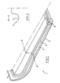
- Fig. 1 the left half of a tunnel sheet 1 is shown.
- the right half is the same in mirror image.
- a carrier edge 5 runs around the central, upwardly curved part of the tunnel plate.
- the carrier edge 5 follows its curvature upwards in the front and rear region of the tunnel plate 1, so that the tunnel itself is continuous from the rear to the front.
- an upwardly open U-profile 6 is formed (see also cross-section according to FIG. 2) with a lateral edge flange 7.
- This U-profile 6 is drawn upwards in a vertical part 8 in the rear part of the tunnel sheet 1.
- this increase could also be smooth and gradual, as is done in the front area of the tunnel sheet 1.
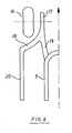
- FIGS. 3 to 5 it can be seen how, with the aid of the sheet metal parts adjoining the tunnel sheet 1 or the support edge 5, a closed hollow profile support 9, which runs around the tunnel sheet 1, is obtained.
- the tunnel sheet 1 with the support edge 5 or U-profile 6 can be seen.
- the upwardly open U-profile 6 is covered by a longitudinal edge area of a subsequent floor plate 10 and welded to the contact surfaces (indicated schematically by crosses).
- a sill plate 11 pointing towards the outside of the vehicle is connected to the base plate 10, by means of which a hollow beam is also formed as a longitudinal beam.
- FIG. 4 shows the front part of the support edge 5 which is bent upwards and to which a bent edge region of an approximately vertical end wall 12 of the passenger compartment is connected in such a way that a hollow profile support 9 which is approximately triangular in cross section results.
- Fig. 5 is a longitudinal section through the rear area of the built-in tunnel sheet 1 with a section through the U-profile 6 in the rear connection to its vertical part 8. Similar to Fig. 3, the hollow profile carrier 9 is also formed here in that the U-profile 6 is covered by the flat edge region of a rear floor panel 13 and is welded to the contact surfaces.
- a tunnel cross member 14 is shown, which is connected via a screw 15 to the underside of the hollow section beam 9.
- screw connection 15 only a connection is created in the hollow profile support 9, but not only on the inside of the passenger compartment, so that no sealing problems with the passenger compartment can occur in this area.
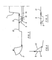
- FIG. 6 schematically shows the arrangement of carriers in a plan view of the front, left area of a motor vehicle.
- a longitudinal member part 17 extends in the area of the wheel housing for a left front wheel 16, which bifurcates into a carrier part 18 and a connecting member 19 after the area of the wheel housing.
- the carrier part 18 merges into the sill 20 designed as a longitudinal hollow carrier, while the connecting carrier 19 creates an approximately longitudinal connection to the hollow profile carrier 9 running around the tunnel. In this way, energy is also introduced into the rigid hollow section support arrangement at the tunnel, in particular in the event of a front impact.
Landscapes
- Engineering & Computer Science (AREA)
- Chemical & Material Sciences (AREA)
- Combustion & Propulsion (AREA)
- Transportation (AREA)
- Mechanical Engineering (AREA)
- Body Structure For Vehicles (AREA)
Abstract
Description
- Die Erfindung betrifft eine Bodenwanne für ein Kraftfahrzeug, insbesondere für einen Personenkraftwagen, nach dem Oberbegriff des Anspruchs 1.
- Bekannte Bodenwannen sind nur aus einem Bodenblech durchgehend hergestellt. Wegen der beträchtlichen Größe dieser Blechteile ergeben sich fertigungstechnische Schwierigkeiten und hohe Werkzeugkosten.
- Es sind auch Bodenwannen für Kraftfahrzeuge bekannt (DE-AS 1 177 499), die aus mehreren geformten und miteinander verbundenen Blechteilen bestehen. An den Verbindungen können durch Überlappungen und entsprechende Ausbildung der Randbereiche Hohlträger zur Versteifung der Bodenwanne gebildet werden.
- Es ist weiter bekannt (DE-OS 26 10 299), Bodenwannen unterschiedlicher Länge und Breite aus gleichen Einzelteilen dadurch herzustellen, daß die Randbereiche der Einzelblechteile mehr oder weniger überlappend verbunden werden.
- Bei vielen Kraftfahrzeugen, insbesondere bei Personenkraftwagen, ist die Bodenwanne im mittleren Bereich in Fahrzeuglängsrichtung in der Form eines Tunnels gewölbt. Ein solcher Tunnel dient zur Verbindung und für die Durchführung von Bauteilen von der Vorderseite des Fahrzeugs zur Rückseite, z.B. für Auspuffrohre, Antriebswellen, Kabelstränge, etc.
- Es ist dazu bekannt, eine Bodenwanne mit Tunnel aus einem separaten Tunnelblech und daran anschließenden, weiteren Blechteilen herzustellen.
- Allgemein ergibt sich durch den in Längsrichtung der Bodenwanne verlaufenden Tunnelbogen eine unerwünscht weiche Bodenstruktur. Zudem sind bei der üblichen Herstellung der Bodenwannenbleche durch Tiefziehen relativ große Radien erforderlich, was ebenfalls zu der unerwünscht weichen Bodenstruktur beiträgt. Dies führt zu Problemen bei der Fahrzeugakustik. Durch die geringe Steifigkeit im Tunnelbereich fehlen zudem Auflage- und Befestigungsmöglichkeiten für weitere Aggregate, z.B. für das Getriebe. Um hier eine Verbesserung zu erzielen, ist es bekannt, mit relativ großem Aufwand zusätzliche Träger und Versteifungselemente einzuschweißen.
- Aufgabe der Erfindung ist es demgegenüber, eine Bodenwanne zu schaffen, die bei einfacher und preiswerter Herstellung eine verbesserte Steifigkeit aufweist.
- Diese Aufgabe wird mit den Merkmalen des Anspruchs 1 gelöst.
- Gemäß Anspruch 1 ist ein in Fahrzeuglängsrichtung verlaufender Tunnel von einem ringförmig geschlossenen Hohlprofilträger umgeben.
- Durch den ringförmig geschlossenen Hohlprofilträger wird eine dynamisch sehr steife Bodenwanne erhalten. Die Krafteinleitung in die Bodenfläche kann daher akustisch günstiger bei verbessertem Schwingungsverhalten erfolgen.
- Tunnelverstärkungen durch zusätzliche Träger und Verstärkungsbauteile können weitgehend entfallen.
- Durch die hohe Steifigkeit im Tunnelbereich sind ohne Zusatzaufwand Lagerungsmöglichkeiten, z.B. für eine Getriebeaufhängung, geschaffen.
- In der Ausführungsform nach Anspruch 2 ist der Tunnel an der Vorder- und Rückseite bogenförmig nach oben gewölbt und in Längsrichtung offen. Der Hohlprofilträger läuft dementsprechend an den Tunnellängsseiten in der Höhe des Fahrzeugbodens und an der Vorder- und Rückseite des Tunnels bogenförmig nach oben gewölbt. Dadurch ergibt sich ein integriertes, vorderes und hinteres Tunneljoch, was eine große Steifigkeit erbringt. Jochbauteile wurden bisher als separate Zusatzbauteile zur Tunnelverstärkung eingeschweißt und können nunmehr entfallen.
- Nach Anspruch 3 wird der Hohlprofilträger durch einen um ein Tunnelblech ringförmig umlaufenden Trägerrand und daran anschließende Blechteile gebildet. Die anschließenden Blechteile überlappen mit Randbereichen den Trägerrand des Tunnelblechs und sind so geformt, daß sich durch die Überlappung und Verbindung der Hohlprofilträger ergibt. Dabei kann auch das Tunnelblech aus mehreren Einzelblechteilen hergestellt sein.
- Mit diesen Merkmalen ergibt sich eine einfache Konstruktion und Herstellungsweise, wobei durch Änderungen in der Überlappungsbreite Variationen in der Länge und Breite der Bodenwanne zur Anpassung an unterschiedliche Fahrzeugtypen möglich sind.
- Nach Anspruch 4 können vorteilhaft an das Tunnelblech bzw. dessen Trägerrand ohne weitere Zwischenbleche relativ großflächige Blechteile direkt angeschlossen werden, wie z.B. ein rechtes und linkes Bodenblech, eine Stirnwand des Fahrgastraums und ein hinteres Bodenblech. Dadurch wird die Herstellung unter Verwendung einer relativ kleinen Anzahl von Blechteilen einfach und preisgünstig.
- Eine besonders bevorzugte Ausführungsform nach Anspruch 5 enthält am Trägerrand des Tunnelblechs ein nach oben offenes U-Profil, das durch einen ebenen Randbereich der anschließenden Blechteile zur Bildung des Hohlprofilträgers geschlossen ist. Damit ergibt sich eine besonders kostengünstige Herstellung der gesamten Hohlprofilträgeranordnung. Eine Variation in der Länge und Breite der Bodenwanne kann einfach durch Verschieben und unterschiedliche Überlappung der Blechteile erreicht werden.
- Eine weitere Erhöhung der Steifigkeit der Bodenwanne wird nach Anspruch 6 dadurch erzielt, daß ein Verbindungsträger von an sich bekannten und üblicherweise vorhandenen Längsträ gern der Bodenwanne zum umlaufenden Hohlprofilträger des Tunnels verläuft, so daß die Längsträger und der tunnel-Hohl-profilträger miteinander verbunden sind.
- Nach Anspruch 7 sind zwei Verbindungsträger vorgesehen, die etwa in Richtung der Verlängerung der Längsseiten des Hohlprofilträgers zur Frontseite des Fahrzeugs hin verlaufen und mit jeweils einem im Bereich eines Radkastens verlaufenden Längsträger verbunden sind. Damit ergibt sich eine Längsträger-Verbindungsträger-Anordnung in Y-Form. Durch diese Anordnung nimmt insbesondere bei einem Frontalaufprall der Hohlprofilträger am Tunnel ebenfalls Energie auf.
- Wie bereits beschrieben, eignet sich der umlaufende Hohlprofilträger wegen der hohen Steifigkeit der Anordnung besonders gut zur Lagerung von zusätzlichen Bauteilen und Aggregaten. Nach Anspruch 8 ist es vorteilhaft, Verschraubungen von Anbauteilen und/oder weiteren Trägerbauteilen direkt am Hohlprofilträger des Tunnels anzubringen, beispielsweise in Form von Schweißmuttern, die innerhalb des Hohlprofilträgers liegen und dort angeschweißt sind. Dadurch wird erreicht, daß zwar der Hohlprofilträger durch die Verschraubung durchbrochen ist, jedoch die Bodenwanne insgesamt zur Fahrgastzelle hin keinen Durchbruch enthält und somit in jedem Fall dicht ist.
- Anhand einer Zeichnung wird eine Ausführungsform der Erfindung mit weiteren Merkmalen, Einzelheiten und Vorteilen näher erläutert.
- Es zeigen
- Fig. 1 eine in der Länge geschnittene Hälfte eines Tunnelblechs,
- Fig. 2 einen Querschnitt durch das Tunnelblech nach Fig. 1 entlang der Linie A-A,
- Fig. 3 die Hälfte eines schematischen Querschnitts durch eine Bodenwanne,
- Fig. 4 einen schematischen Längsschnitt im vorderen Bereich des Tunnelblechs,
- Fig. 5 einen schematischen Längsschnitt im hinteren Bereich des Tunnelblechs,
- Fig. 6 eine schematische Draufsicht auf die Trägeranordnung im vorderen, linken Bereich eines Personenkraftwagens.
- In Fig. 1 ist die linke Hälfte eines Tunnelblechs 1 dargestellt. Die rechte Hälfte ist dazu spiegelbildlich gleich.
- Um den mittleren, nach oben gewölbten Teil des Tunnelblechs läuft ein Trägerrand 5. Der Trägerrand 5 folgt im vorderen und hinteren Bereich des Tunnelblechs 1 dessen Wölbung nach oben, so daß der Tunnel selbst von hinten nach vorne durchgängig ist.
- Im Trägerrand 5 ist ein nach oben offenes U-Profil 6 geformt (sh. auch Querschnitt nach Fig. 2) mit einem seitlichen Randflansch 7. Dieses U-Profil 6 ist im rückwärtigen Teil des Tunnelblechs 1 in einem senkrechten Teil 8 nach oben gezogen. Dieser Anstieg könnte aber auch gleitend und allmählich erfolgen, so wie dies im vorderen Bereich des Tunnelblechs 1 durchgeführt ist.
- Aus den Fig. 3 bis 5 ist zu ersehen, wie mit Hilfe der an das Tunnelblech 1 bzw. den Trägerrand 5 anschließenden Blechteile ein geschlossener, am Tunnelblech 1 umlaufende Hohlprofilträger 9 erhalten wird.
- Im Querschnitt der Fig. 3 ist das Tunnelblech 1 mit dem Trägerrand 5 bzw. U-Profil 6 zu erkennen. Das nach oben offene U-Profil 6 wird von einem Längsrandbereich eines anschließenden Bodenblechs 10 überdeckt und an den Anlageflächen verschweißt (schematisch durch Kreuze angedeutet). Mit dem Bodenblech 10 ist ein zur Fahrzeugaußenseite hin weisendes Schwellerblech 11 verbunden, durch das ebenfalls ein Hohlträger als Längsträger gebildet wird.
- In Fig. 4 ist der vordere Teil des nach oben abgekanteten Trägerrandes 5 dargestellt, mit dem ein abgebogener Randbereich einer etwa senkrechten Stirnwand 12 des Fahrgastraums so verbunden ist, daß sich ein im Querschnitt etwa dreieckförmiger Hiohlprofilträger 9 ergibt.
- In Fig. 5 ist ein Längsschnitt durch den hinteren Bereich des eingebauten Tunnelblechs 1 dargestellt mit einem Schnitt durch das U-Profil 6 im rückwärtigen Anschluß an dessen senkrechten Teil 8. Ähnlich wie in Fig. 3 wird der Hohlprofilträger 9 auch hier dadurch gebildet, daß das U-Profil 6 durch den ebenen Randbereich eines hinteren Bodenblechs 13 überdeckt und an den Anlageflächen verschweißt ist.
- Damit ergibt sich ein insgesamt am Tunnelblech 1 umlaufender Hohlprofilträger 9, der die Steifigkeit der Bodenwanne in diesem Bereich erheblich vergrößert.
- In Fig. 3 ist ein Tunnelquerträger 14 eingezeichnet, der über eine Verschraubung 15 mit der Unterseite des Hohlprofilträgers 9 verbunden ist. Bei einer solchen Anordnung der Verschraubung 15 wird nur eine Verbindung in den Hohlprofilträger 9 geschaffen, jedoch nicht nur Innenseite des Fahrgastraums hin, so daß keine Dichtigkeitsprobleme zum Fahrgastraum hin in diesem Bereich auftreten können.
- Fig. 6 zeigt schematische die Anordnung von Trägern in einer Draufsicht auf den vorderen, linken Bereich eines Kraftfahrzeugs. Von der Vorderseite her erstreckt sich im Bereich des Radkastens für ein linkes Vorderrad 16 ein Längsträgerteil 17, das sich nach dem Bereich des Radkastens Y-förmig in ein Trägerteil 18 und einen Verbindungsträger 19 gabelt. Das Trägerteil 18 geht in den als Längs-Hohlträger ausgebildeten Schweller 20 über, während der Verbindungsträger 19 eine etwa in Längsrichtung verlaufende Verbindung zum am Tunnel umlaufenden Hohlprofilträger 9 herstellt. Damit wird insbesondere bei einem Frontaufprall auch Energie in die steife Hohlprofilträgeranordnung am Tunnel eingeleitet.
Claims (8)
dadurch gekennzeichnet,
daß ein in Fahrzeuglängsrichtung verlaufender Tunnel von einem ringförmig geschlossenen Hohlprofilträger (9) umgeben ist.
daß der Hohlprofilträger an der Vorderseite des Tunnels und an der Rückseite des Tunnels bogenförmig nach oben verläuft, so daß ein vorderes und hinteres Tunneljoch als integrierte Bauteile gebildet sind.
Applications Claiming Priority (2)
| Application Number | Priority Date | Filing Date | Title |
|---|---|---|---|
| DE3831480 | 1988-09-16 | ||
| DE3831480A DE3831480A1 (de) | 1988-09-16 | 1988-09-16 | Bodenwanne fuer ein kraftfahrzeug |
Publications (3)
| Publication Number | Publication Date |
|---|---|
| EP0359141A2 true EP0359141A2 (de) | 1990-03-21 |
| EP0359141A3 EP0359141A3 (en) | 1990-08-29 |
| EP0359141B1 EP0359141B1 (de) | 1993-03-17 |
Family
ID=6363059
Family Applications (1)
| Application Number | Title | Priority Date | Filing Date |
|---|---|---|---|
| EP89116598A Expired - Lifetime EP0359141B1 (de) | 1988-09-16 | 1989-09-08 | Bodenwanne für ein Kraftfahrzeug |
Country Status (3)
| Country | Link |
|---|---|
| EP (1) | EP0359141B1 (de) |
| DE (2) | DE3831480A1 (de) |
| ES (1) | ES2039055T3 (de) |
Cited By (1)
| Publication number | Priority date | Publication date | Assignee | Title |
|---|---|---|---|---|
| US11021192B2 (en) * | 2016-07-11 | 2021-06-01 | Honda Motor Co., Ltd. | Underbody structure |
Families Citing this family (7)
| Publication number | Priority date | Publication date | Assignee | Title |
|---|---|---|---|---|
| DE19724557B4 (de) * | 1997-06-11 | 2004-09-16 | Adam Opel Ag | Selbsttragende Fahrzeugkarosserie |
| DE10005245B4 (de) | 2000-02-05 | 2004-04-01 | Daimlerchrysler Ag | Tunnelbereich einer Bodenstruktur einer Rohbaukarosserie eines Kraftfahrzeugs und Querbrücke |
| DE10232844B4 (de) * | 2002-07-19 | 2015-10-01 | Volkswagen Ag | Bodenlängsträgeranordnung an Kraftfahrzeugen |
| DE20321813U1 (de) * | 2003-03-04 | 2010-07-01 | Audi Ag | Tragstruktur eines Kraftfahrzeugs |
| DE10309635B4 (de) * | 2003-03-04 | 2008-07-03 | Audi Ag | Kraftfahrzeug mit einer einen Tunnel aufweisenden Bodentragstruktur |
| DE102009030575A1 (de) * | 2009-06-26 | 2010-12-30 | GM Global Technology Operations, Inc., Detroit | Karosserie für ein Kraftfahrzeug mit einer Bodenstruktur |
| DE102016203441B4 (de) * | 2016-03-02 | 2020-03-26 | Volkswagen Aktiengesellschaft | Karosserie-Bodenstruktur für ein Fahrzeug |
Family Cites Families (6)
| Publication number | Priority date | Publication date | Assignee | Title |
|---|---|---|---|---|
| DE1177499B (de) * | 1955-06-18 | 1964-09-03 | Daimler Benz Ag | Bodenwanne fuer Kraftfahrzeuge |
| GB1116738A (en) * | 1966-04-06 | 1968-06-12 | Vauxhall Motors Ltd | Motor vehicle sheet metal bodies |
| US3419303A (en) * | 1967-02-17 | 1968-12-31 | Budd Co | Lower body construction for automobiles |
| DE2610299A1 (de) * | 1976-03-12 | 1977-09-15 | Audi Nsu Auto Union Ag | Verfahren zum herstellen von bodenwannen mit hohltraegern fuer kraftfahrzeuge |
| DE2848593A1 (de) * | 1978-11-09 | 1980-05-22 | Daimler Benz Ag | Randkantenpaar eines bodentunnels |
| DE3720946A1 (de) * | 1986-07-03 | 1988-01-07 | Volkswagen Ag | Bodengruppe fuer ein kraftfahrzeug |
-
1988
- 1988-09-16 DE DE3831480A patent/DE3831480A1/de active Granted
-
1989
- 1989-09-08 ES ES198989116598T patent/ES2039055T3/es not_active Expired - Lifetime
- 1989-09-08 DE DE8989116598T patent/DE58903794D1/de not_active Expired - Fee Related
- 1989-09-08 EP EP89116598A patent/EP0359141B1/de not_active Expired - Lifetime
Cited By (1)
| Publication number | Priority date | Publication date | Assignee | Title |
|---|---|---|---|---|
| US11021192B2 (en) * | 2016-07-11 | 2021-06-01 | Honda Motor Co., Ltd. | Underbody structure |
Also Published As
| Publication number | Publication date |
|---|---|
| EP0359141B1 (de) | 1993-03-17 |
| DE58903794D1 (de) | 1993-04-22 |
| DE3831480C2 (de) | 1992-03-12 |
| DE3831480A1 (de) | 1990-03-22 |
| EP0359141A3 (en) | 1990-08-29 |
| ES2039055T3 (es) | 1993-08-16 |
Similar Documents
| Publication | Publication Date | Title |
|---|---|---|
| DE10147117B4 (de) | Fahrzeugseitenschwellerstruktur | |
| DE69825711T2 (de) | Fahrerhaus für eine Baumaschine | |
| DE10108287B4 (de) | Karosseriestruktur | |
| DE69807988T2 (de) | Verstärkungselement für Kfz-Hohlprofile, mit verminderter Wanddicke am Endabschnitt | |
| DE19642833C2 (de) | Vorderwandrahmen für eine selbsttragende Karosserie eines Personenkraftwagens und Verfahren zu seiner Herstellung | |
| DE10391812B4 (de) | Karosseriestruktur | |
| DE3720847C2 (de) | ||
| DE3707554A1 (de) | Tragschiene fuer einen fahrzeugrahmen und fahrzeugunterbau | |
| EP1738943B1 (de) | Türstruktur eines Kraftfahrzeuges | |
| DE3343682A1 (de) | Tragender aufbau fuer ein kraftfahrzeug | |
| DE2809379C2 (de) | Dachaufbau für Kraftfahrzeuge, insbesondere Personenwagen, mit einem einen Rahmenboden aufweisenden Schiebedach | |
| DE102009048335A1 (de) | Sitzquerträger für Karosserieunterboden | |
| DE102015203309B4 (de) | Fahrzeug-Karosseriestruktur | |
| EP0476351B1 (de) | Fahrzeugtür | |
| EP0359141B1 (de) | Bodenwanne für ein Kraftfahrzeug | |
| DE19735640B4 (de) | Befestigung eines Sicherheitsgurtes | |
| DE60024829T2 (de) | Profil für eine Karosserie | |
| EP1108640B1 (de) | Dachbefestigung an Kraftfahrzeugen | |
| DE19821107C2 (de) | Rohbaukarosserie für einen Personenkraftwagen | |
| EP0096846A2 (de) | Aufbau für Kraftfahrzeuge, insbesondere Personenkraftwagen, und Verfahren zur Herstellung eines solchen Aufbaus | |
| DE4135361A1 (de) | Hilfsrahmen fuer kraftfahrzeuge | |
| DE102007061209B4 (de) | Seitentür für einen Kraftwagen | |
| DE4224303A1 (de) | Verstärkungselement für Seitenwände von Automobilen sowie Verfahren zur Herstellung derartiger Verstärkungselemente | |
| EP0580605B1 (de) | Tragstruktur einer karosserie eines personenkraftwagens | |
| DE19923737B4 (de) | Mehrteilige Stirnwand für eine Kraftfahrzeugrohbaukarosserie |
Legal Events
| Date | Code | Title | Description |
|---|---|---|---|
| PUAI | Public reference made under article 153(3) epc to a published international application that has entered the european phase |
Free format text: ORIGINAL CODE: 0009012 |
|
| 17P | Request for examination filed |
Effective date: 19890908 |
|
| AK | Designated contracting states |
Kind code of ref document: A2 Designated state(s): DE ES FR GB IT |
|
| PUAL | Search report despatched |
Free format text: ORIGINAL CODE: 0009013 |
|
| AK | Designated contracting states |
Kind code of ref document: A3 Designated state(s): DE ES FR GB IT |
|
| 17Q | First examination report despatched |
Effective date: 19911106 |
|
| ITF | It: translation for a ep patent filed | ||
| GRAA | (expected) grant |
Free format text: ORIGINAL CODE: 0009210 |
|
| AK | Designated contracting states |
Kind code of ref document: B1 Designated state(s): DE ES FR GB IT |
|
| REF | Corresponds to: |
Ref document number: 58903794 Country of ref document: DE Date of ref document: 19930422 |
|
| GBT | Gb: translation of ep patent filed (gb section 77(6)(a)/1977) |
Effective date: 19930402 |
|
| ET | Fr: translation filed | ||
| REG | Reference to a national code |
Ref country code: ES Ref legal event code: FG2A Ref document number: 2039055 Country of ref document: ES Kind code of ref document: T3 |
|
| PLBI | Opposition filed |
Free format text: ORIGINAL CODE: 0009260 |
|
| 26 | Opposition filed |
Opponent name: BAYERISCHE MOTOREN WERKE AKTIENGESELLSCHAFT Effective date: 19931217 |
|
| PLBN | Opposition rejected |
Free format text: ORIGINAL CODE: 0009273 |
|
| STAA | Information on the status of an ep patent application or granted ep patent |
Free format text: STATUS: OPPOSITION REJECTED |
|
| 27O | Opposition rejected |
Effective date: 19950618 |
|
| REG | Reference to a national code |
Ref country code: GB Ref legal event code: IF02 |
|
| PGFP | Annual fee paid to national office [announced via postgrant information from national office to epo] |
Ref country code: ES Payment date: 20050906 Year of fee payment: 17 |
|
| PGFP | Annual fee paid to national office [announced via postgrant information from national office to epo] |
Ref country code: DE Payment date: 20050930 Year of fee payment: 17 |
|
| PGFP | Annual fee paid to national office [announced via postgrant information from national office to epo] |
Ref country code: GB Payment date: 20060821 Year of fee payment: 18 |
|
| PGFP | Annual fee paid to national office [announced via postgrant information from national office to epo] |
Ref country code: FR Payment date: 20060919 Year of fee payment: 18 |
|
| PGFP | Annual fee paid to national office [announced via postgrant information from national office to epo] |
Ref country code: IT Payment date: 20060930 Year of fee payment: 18 |
|
| PG25 | Lapsed in a contracting state [announced via postgrant information from national office to epo] |
Ref country code: DE Free format text: LAPSE BECAUSE OF NON-PAYMENT OF DUE FEES Effective date: 20070403 |
|
| GBPC | Gb: european patent ceased through non-payment of renewal fee |
Effective date: 20070908 |
|
| REG | Reference to a national code |
Ref country code: FR Ref legal event code: ST Effective date: 20080531 |
|
| PG25 | Lapsed in a contracting state [announced via postgrant information from national office to epo] |
Ref country code: FR Free format text: LAPSE BECAUSE OF NON-PAYMENT OF DUE FEES Effective date: 20071001 |
|
| PG25 | Lapsed in a contracting state [announced via postgrant information from national office to epo] |
Ref country code: GB Free format text: LAPSE BECAUSE OF NON-PAYMENT OF DUE FEES Effective date: 20070908 |
|
| REG | Reference to a national code |
Ref country code: ES Ref legal event code: FD2A Effective date: 20070910 |
|
| PG25 | Lapsed in a contracting state [announced via postgrant information from national office to epo] |
Ref country code: ES Free format text: LAPSE BECAUSE OF NON-PAYMENT OF DUE FEES Effective date: 20070910 |
|
| PG25 | Lapsed in a contracting state [announced via postgrant information from national office to epo] |
Ref country code: IT Free format text: LAPSE BECAUSE OF NON-PAYMENT OF DUE FEES Effective date: 20070908 |