EP0358771A1 - Systeme de commande de puissance pour une machine-outil a faisceau laser cnc - Google Patents
Systeme de commande de puissance pour une machine-outil a faisceau laser cnc Download PDFInfo
- Publication number
- EP0358771A1 EP0358771A1 EP89901586A EP89901586A EP0358771A1 EP 0358771 A1 EP0358771 A1 EP 0358771A1 EP 89901586 A EP89901586 A EP 89901586A EP 89901586 A EP89901586 A EP 89901586A EP 0358771 A1 EP0358771 A1 EP 0358771A1
- Authority
- EP
- European Patent Office
- Prior art keywords
- machining
- velocity
- laser
- cnc
- pulse
- Prior art date
- Legal status (The legal status is an assumption and is not a legal conclusion. Google has not performed a legal analysis and makes no representation as to the accuracy of the status listed.)
- Granted
Links
Images


Classifications
-
- G—PHYSICS
- G05—CONTROLLING; REGULATING
- G05B—CONTROL OR REGULATING SYSTEMS IN GENERAL; FUNCTIONAL ELEMENTS OF SUCH SYSTEMS; MONITORING OR TESTING ARRANGEMENTS FOR SUCH SYSTEMS OR ELEMENTS
- G05B19/00—Programme-control systems
- G05B19/02—Programme-control systems electric
- G05B19/18—Numerical control [NC], i.e. automatically operating machines, in particular machine tools, e.g. in a manufacturing environment, so as to execute positioning, movement or co-ordinated operations by means of programme data in numerical form
- G05B19/416—Numerical control [NC], i.e. automatically operating machines, in particular machine tools, e.g. in a manufacturing environment, so as to execute positioning, movement or co-ordinated operations by means of programme data in numerical form characterised by control of velocity, acceleration or deceleration
- G05B19/4163—Adaptive control of feed or cutting velocity
-
- B—PERFORMING OPERATIONS; TRANSPORTING
- B23—MACHINE TOOLS; METAL-WORKING NOT OTHERWISE PROVIDED FOR
- B23K—SOLDERING OR UNSOLDERING; WELDING; CLADDING OR PLATING BY SOLDERING OR WELDING; CUTTING BY APPLYING HEAT LOCALLY, e.g. FLAME CUTTING; WORKING BY LASER BEAM
- B23K26/00—Working by laser beam, e.g. welding, cutting or boring
- B23K26/08—Devices involving relative movement between laser beam and workpiece
- B23K26/083—Devices involving movement of the workpiece in at least one axial direction
- B23K26/0853—Devices involving movement of the workpiece in at least in two axial directions, e.g. in a plane
-
- G—PHYSICS
- G05—CONTROLLING; REGULATING
- G05B—CONTROL OR REGULATING SYSTEMS IN GENERAL; FUNCTIONAL ELEMENTS OF SUCH SYSTEMS; MONITORING OR TESTING ARRANGEMENTS FOR SUCH SYSTEMS OR ELEMENTS
- G05B2219/00—Program-control systems
- G05B2219/30—Nc systems
- G05B2219/43—Speed, acceleration, deceleration control ADC
- G05B2219/43129—Speed as function of curvature, in curves, corners smaller than in straight line
-
- G—PHYSICS
- G05—CONTROLLING; REGULATING
- G05B—CONTROL OR REGULATING SYSTEMS IN GENERAL; FUNCTIONAL ELEMENTS OF SUCH SYSTEMS; MONITORING OR TESTING ARRANGEMENTS FOR SUCH SYSTEMS OR ELEMENTS
- G05B2219/00—Program-control systems
- G05B2219/30—Nc systems
- G05B2219/43—Speed, acceleration, deceleration control ADC
- G05B2219/43147—Control power of tool as function of speed, velocity of movement
-
- G—PHYSICS
- G05—CONTROLLING; REGULATING
- G05B—CONTROL OR REGULATING SYSTEMS IN GENERAL; FUNCTIONAL ELEMENTS OF SUCH SYSTEMS; MONITORING OR TESTING ARRANGEMENTS FOR SUCH SYSTEMS OR ELEMENTS
- G05B2219/00—Program-control systems
- G05B2219/30—Nc systems
- G05B2219/45—Nc applications
- G05B2219/45165—Laser machining
-
- G—PHYSICS
- G05—CONTROLLING; REGULATING
- G05B—CONTROL OR REGULATING SYSTEMS IN GENERAL; FUNCTIONAL ELEMENTS OF SUCH SYSTEMS; MONITORING OR TESTING ARRANGEMENTS FOR SUCH SYSTEMS OR ELEMENTS
- G05B2219/00—Program-control systems
- G05B2219/30—Nc systems
- G05B2219/49—Nc machine tool, till multiple
- G05B2219/49164—Corner, making corner
Definitions
- the present invention relates to a power control method in a CNC (computerized numerical control) laser machining system, and more particularly to such a method in which an improvement is made in the machining of a corner portion.
- Laser machining apparatuses are extensively used in conjunction with a numerical control apparatus, because a workpiece can be machined thereby to form a complex shape at a high speed.
- a direction in which a laser beam is moved must be reversed while temporarily making a speed of the laser beam relative to the workpiece zero when the workpiece is machined to form a corner portion or an acute angle edge portion. That is, when machining the corner portion, the moving speed of the laser beam is decelerated, stopped, and then accelerated.
- Fig. 5 illustrates a workpiece 40 machined by the laser beam to form a groove 41.
- the laser beam is moved relative to the workpiece 40 in the direction indicated by an arrow A.
- the speed at which the laser beam is moved is decelerated, the beam is temporarily stopped at the corner portion 42, and the beam is then accelerated after passing the corner portion 42.
- the speed of the laser beam relative to the workpiece 40 is reduced when the laser beam passes through the corner portion 42, and therefore, a defective melting occurs in the corner portion due to a storage of thermal energy and excessive heat absorption when the machining is performed under not only a CW beam condition but also a pulsed beam condition, and thus the cutting accuracy and the quality of the final product are greatly reduced.
- Fig. 6 is an enlargement of the corner portion shown in Fig. 5, in which the corner portion of the groove machined by the laser beam is illustrated in detail. Portions B and C indicated by oblique lines alongside of the corner portion are melted down due to the lowering of the relative speed of the laser beam, whereby the machining accuracy is lowered. Further, the thermally influenced regions are extended to portions D and E, to thereby exert adverse influence upon the material of the workpiece and increase the surface roughness of the engraved surface.
- the machining of the corner portion can be controlled in such a manner that a pulse duty ratio is lowered in accordance with to the lowering of the speed at which the laser beam is moved, to thereby reduce the laser output.
- This method is not satisfactory, however, in that a dross-free machining cannot be accomplished over an extensive region.
- the present invention has been created in view of the foregoing circumstances, and an object of the invention is to provide a power control method in a CNC laser machining system in which an improvement is made in the machining of a corner portion.
- a power control method in a CNC laser machining system including a CNC apparatus and a laser machining apparatus for machining a workpiece, the method comprising the step of:
- Fig. 1 is a block diagram showing a CNC (computerized numerical control) laser machining apparatus as used in the present invention.
- a CNC apparatus is generally designated by reference numeral 10, which controls the laser machining apparatus.
- a memory 11 is provided in the CNC apparatus for storing instruction data therein.
- a pre-processing means 12 separates the instruction data into two kinds of data and translates the latter into executable data. More specifically, the instruction data is separated into position/velocity control data for controlling the movement of an X-Y table on which a workpiece is fixedly mounted, and an output power control signal for controlling the output power of a laser beam.
- the position/velocity control data is fed to a pulse distribution means 13.
- the pulse distribution means 13 supplies pulses to both the X-axis and Y-axis control means 14 and 15 with X-axis and Y-axis distribution pulses, respectively, which are produced from the position/control data.
- the distribution pulses are subjected to acceleration/deceleration processings to provide X-axis and Y-axis drive signals.
- Each of such drive signals is supplied to the associated servo motor drive circuit (not shown) for driving a servo motor coupled thereto, whereby the movement of the X-Y table is controlled.
- the X-axis and Y-axis drive signals subjected to acceleration/deceleration processing are fed to a real velocity computing means 16, and the computing means 16 computes a real velocity of the X-Y table based upon the X-axis and Y-axis drive signals fed thereto.
- the real velocity can be obtained by composing vectors indicating the X-axis and Y-axis velocities.
- the resultant velocity corresponds in substance to the velocities of the servo motors or is substantially equal to a speed of the X-Y table relative to a laser head. Where a more accurate velocity is needed, this can be obtained from a velocity feedback device provided in association with the servo motor, for example, a pulse coder.
- the output power control signal fed from the pre-processing means 12 is supplied to the output power control means 17 which, in response thereto, controls the output of the laser beam.
- the output power control means 17 delivers the output control signal input to a high frequency power supply 3 1 .
- the control means 17 controls the high frequency power supply 31 so that the output power of the laser beam is reduced in accordance with the reduction of the velocity.
- a display unit 21 is provided to display, for example, position, velocity, and machining data.
- a CRT cathode ray tube
- an LCD liquid crystal display
- a keyboard 22 is provided for imputting the various kinds of data and parameters including the instruction data, to the laser machining apparatus.
- the radio frequency power supply 31 supplies a radio frequency power, and due to the application of the radio frequency power thereto, radio frequency discharges occur in the laser tube 32 and a laser beam is thereby oscillated and amplified.
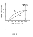
- Fig. 2 is a graphical representation showing a relationship between a duty ratio and a velocity of the laser beam relative to the X-Y table.
- the axis of abscissa represents the duty ratio (%) and the axis of ordinate represents a feeding speed Fc (M/min) of the X-Y table.
- the duty ratio may be changed either linearly as indicated by the line a or non-linearly as indicated by the curve b, and the selection thereof is determined in accordance with various conditions, such as the material of the workpiece, the thickness thereof, the machining velocity, and the machining accuracy as required.
- the excessive melting loss at the corner portion can be effectively prevented which may otherwise be caused by the storage of the heat energy in the workpiece and excessive absorption of the heat thereinto, whereby a dross-free machining is attained.
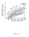
- Fig. 3 is also a graphical representation in which desirable machining regions are indicated in relation to the curve of the pulse duty ratio vs. the feeding speed.
- the axis of abscissa represents the duty ratio (%) and the axis of ordinate represents a feeding speed (M/min).
- the pulse machining performed under the pulse frequency of f1 good machining results are obtained only in the region D1 if the pulse duty ratio is reduced in accordance with the lowering of the feeding speed, and good machining results can not be obtained outside of the region D1.
- good machining results or dross-free conditions are obtained in the region D2, and under the pulse frequency of f3, in the region D3.
- the pulse frequency should be stepwise reduced from f1 to f2 and then f2 to f3 in accordance with the reduction of the pulse duty ratio.
- Fig. 4 is also a graphical representation which illustrates the case wherein the pulse frequency is continuously varied.
- the values of each axis are the same as in Fig. 3 respectively, but as illustrated therein, the pulse frequency may be changed continuously.
- the manner of continuously varying the pulse frequency is determined on an experimental basis, depending upon the material of the workpiece to be machined and the thickness thereof, etc.
Landscapes
- Engineering & Computer Science (AREA)
- Physics & Mathematics (AREA)
- Optics & Photonics (AREA)
- Human Computer Interaction (AREA)
- Manufacturing & Machinery (AREA)
- General Physics & Mathematics (AREA)
- Automation & Control Theory (AREA)
- Plasma & Fusion (AREA)
- Mechanical Engineering (AREA)
- Laser Beam Processing (AREA)
- Numerical Control (AREA)
- Lasers (AREA)
Abstract
Applications Claiming Priority (2)
| Application Number | Priority Date | Filing Date | Title |
|---|---|---|---|
| JP63018603A JPH01197084A (ja) | 1988-01-29 | 1988-01-29 | Cncレーザ加工機のパワー制御方式 |
| JP18603/88 | 1988-01-29 |
Publications (3)
| Publication Number | Publication Date |
|---|---|
| EP0358771A4 EP0358771A4 (fr) | 1990-01-23 |
| EP0358771A1 true EP0358771A1 (fr) | 1990-03-21 |
| EP0358771B1 EP0358771B1 (fr) | 1993-09-08 |
Family
ID=11976219
Family Applications (1)
| Application Number | Title | Priority Date | Filing Date |
|---|---|---|---|
| EP89901586A Expired - Lifetime EP0358771B1 (fr) | 1988-01-29 | 1989-01-18 | Systeme de commande de puissance pour une machine-outil a faisceau laser cnc |
Country Status (5)
| Country | Link |
|---|---|
| US (1) | US5012069A (fr) |
| EP (1) | EP0358771B1 (fr) |
| JP (1) | JPH01197084A (fr) |
| DE (1) | DE68908987T2 (fr) |
| WO (1) | WO1989007035A1 (fr) |
Cited By (3)
| Publication number | Priority date | Publication date | Assignee | Title |
|---|---|---|---|---|
| EP0506968A1 (fr) * | 1990-10-18 | 1992-10-07 | Fanuc Ltd. | Procede d'usinage a l'aide de faisceaux laser |
| WO1995010077A1 (fr) * | 1993-10-06 | 1995-04-13 | Electro Scientific Industries, Inc. | Systeme de coordination de la localisation et de l'emission d'un faisceau de rayonnement |
| CN1292871C (zh) * | 1994-02-24 | 2007-01-03 | 三菱电机株式会社 | 激光切割装置 |
Families Citing this family (20)
| Publication number | Priority date | Publication date | Assignee | Title |
|---|---|---|---|---|
| JPH05111783A (ja) * | 1991-10-19 | 1993-05-07 | Fanuc Ltd | レーザ加工における穴明け加工方法 |
| JP2634732B2 (ja) * | 1992-06-24 | 1997-07-30 | ファナック株式会社 | レーザ加工装置 |
| JPH07112287A (ja) * | 1993-10-15 | 1995-05-02 | Fanuc Ltd | Ncレーザ装置 |
| JP3159593B2 (ja) * | 1994-02-28 | 2001-04-23 | 三菱電機株式会社 | レーザ加工方法及びその装置 |
| JP3515838B2 (ja) * | 1995-10-02 | 2004-04-05 | ファナック株式会社 | レーザ加工装置、レーザ加工方法、及びプログラム作成装置 |
| US5932119A (en) * | 1996-01-05 | 1999-08-03 | Lazare Kaplan International, Inc. | Laser marking system |
| US6325697B1 (en) | 1999-11-24 | 2001-12-04 | Glassline Corporation | CNC machine tools |
| US7133734B2 (en) | 2002-09-20 | 2006-11-07 | Richard Backer | Method for creating a sculpture |
| DE102004011769B3 (de) * | 2004-03-09 | 2005-08-18 | Kuka Schweissanlagen Gmbh | Verfahren zum Laserbearbeiten und Lasereinrichtung |
| JP2006159254A (ja) * | 2004-12-07 | 2006-06-22 | Disco Abrasive Syst Ltd | レーザー加工装置 |
| EP2163339B1 (fr) * | 2008-09-11 | 2016-11-02 | Bystronic Laser AG | Installation de coupe au laser destinée à couper une pièce usinée à l'aide d'un rayon laser à vitesse de coupe variable |
| JP2010125489A (ja) * | 2008-11-28 | 2010-06-10 | Keyence Corp | レーザマーカ及びレーザマーキングシステム |
| DE102011001474A1 (de) * | 2011-03-22 | 2012-09-27 | Carl Zeiss Microimaging Gmbh | Laser-Mikrodissektionsverfahren und Laser-Mikrodissektionsvorrichtung |
| JP6018744B2 (ja) | 2011-11-02 | 2016-11-02 | 日酸Tanaka株式会社 | レーザ切断方法及びレーザ切断装置 |
| KR102245810B1 (ko) * | 2013-03-15 | 2021-04-30 | 일렉트로 싸이언티픽 인더스트리이즈 인코포레이티드 | Aod 라우트 프로세싱을 위한 레이저 시스템들 및 방법들 |
| CN104759753B (zh) * | 2015-03-30 | 2016-08-31 | 江苏大学 | 多系统自动化协调工作提高激光诱导空化强化的方法 |
| JP2018030162A (ja) | 2016-08-26 | 2018-03-01 | ファナック株式会社 | レーザ制御装置 |
| JP6450734B2 (ja) * | 2016-11-22 | 2019-01-09 | ファナック株式会社 | 数値制御装置 |
| CN110087817B (zh) | 2016-12-08 | 2022-05-17 | 可利雷斯股份有限公司 | 激光加工设备和方法 |
| US11850679B2 (en) | 2017-12-29 | 2023-12-26 | Corelase Oy | Laser processing apparatus and method |
Citations (1)
| Publication number | Priority date | Publication date | Assignee | Title |
|---|---|---|---|---|
| US4638145A (en) * | 1984-11-20 | 1987-01-20 | Mitsubishi Denki Kabushiki Kaisha | Laser machining apparatus |
Family Cites Families (5)
| Publication number | Priority date | Publication date | Assignee | Title |
|---|---|---|---|---|
| JPS61226197A (ja) * | 1985-03-29 | 1986-10-08 | Mitsubishi Electric Corp | レ−ザ加工制御装置 |
| JPS61232085A (ja) * | 1985-04-09 | 1986-10-16 | Mitsubishi Electric Corp | レ−ザ切断方法および装置 |
| JPS6224886A (ja) * | 1985-07-24 | 1987-02-02 | Mitsubishi Electric Corp | レ−ザ加工装置 |
| US4758705A (en) * | 1985-08-06 | 1988-07-19 | Eastman Kodak Company | Method and apparatus for texturing a roller |
| JP2804027B2 (ja) * | 1987-07-13 | 1998-09-24 | ファナック 株式会社 | レーザ出力補正方式 |
-
1988
- 1988-01-29 JP JP63018603A patent/JPH01197084A/ja active Pending
-
1989
- 1989-01-18 EP EP89901586A patent/EP0358771B1/fr not_active Expired - Lifetime
- 1989-01-18 US US07/415,233 patent/US5012069A/en not_active Expired - Fee Related
- 1989-01-18 DE DE89901586T patent/DE68908987T2/de not_active Expired - Fee Related
- 1989-01-18 WO PCT/JP1989/000041 patent/WO1989007035A1/fr active IP Right Grant
Patent Citations (1)
| Publication number | Priority date | Publication date | Assignee | Title |
|---|---|---|---|---|
| US4638145A (en) * | 1984-11-20 | 1987-01-20 | Mitsubishi Denki Kabushiki Kaisha | Laser machining apparatus |
Non-Patent Citations (1)
| Title |
|---|
| See also references of WO8907035A1 * |
Cited By (5)
| Publication number | Priority date | Publication date | Assignee | Title |
|---|---|---|---|---|
| EP0506968A1 (fr) * | 1990-10-18 | 1992-10-07 | Fanuc Ltd. | Procede d'usinage a l'aide de faisceaux laser |
| EP0506968A4 (en) * | 1990-10-18 | 1993-06-02 | Fanuc Ltd. | Method of working with laser beam |
| WO1995010077A1 (fr) * | 1993-10-06 | 1995-04-13 | Electro Scientific Industries, Inc. | Systeme de coordination de la localisation et de l'emission d'un faisceau de rayonnement |
| US5453594A (en) * | 1993-10-06 | 1995-09-26 | Electro Scientific Industries, Inc. | Radiation beam position and emission coordination system |
| CN1292871C (zh) * | 1994-02-24 | 2007-01-03 | 三菱电机株式会社 | 激光切割装置 |
Also Published As
| Publication number | Publication date |
|---|---|
| EP0358771A4 (fr) | 1990-01-23 |
| US5012069A (en) | 1991-04-30 |
| EP0358771B1 (fr) | 1993-09-08 |
| DE68908987T2 (de) | 1994-01-05 |
| WO1989007035A1 (fr) | 1989-08-10 |
| DE68908987D1 (de) | 1993-10-14 |
| JPH01197084A (ja) | 1989-08-08 |
Similar Documents
| Publication | Publication Date | Title |
|---|---|---|
| EP0358771B1 (fr) | Systeme de commande de puissance pour une machine-outil a faisceau laser cnc | |
| US4403134A (en) | Method and apparatus for cutting by means of a laser beam | |
| EP0445297B1 (fr) | Methode d'usinage par laser | |
| CN2860712Y (zh) | 大功率固体激光平面切割机 | |
| US5906459A (en) | Laser-assisted milling process | |
| US5449881A (en) | Laser beam machine | |
| US5093549A (en) | Laser cutting machine | |
| EP0437676A1 (fr) | Machine de coupage au laser | |
| JPH0363475B2 (fr) | ||
| EP0718070A1 (fr) | Procede d'usinage au laser | |
| JP2743673B2 (ja) | 三次元レーザ加工装置 | |
| JP2000052076A (ja) | レーザー加工装置及び加工ヘッド駆動方法 | |
| JPH0230388A (ja) | レーザ切断方法 | |
| JPH02179373A (ja) | レーザ加工機用nc制御装置 | |
| JPS61232085A (ja) | レ−ザ切断方法および装置 | |
| JPS6372495A (ja) | レ−ザ加工装置 | |
| JP2845552B2 (ja) | パルスレーザ加工方法 | |
| JPH10328938A (ja) | ワイヤ放電加工方法及び装置 | |
| JP2001001151A (ja) | プラズマ加工機によるコーナ部切断方法およびその装置 | |
| JPS60231587A (ja) | レ−ザ加工装置 | |
| JP2932293B2 (ja) | レーザ切断方法 | |
| JPS59215291A (ja) | レ−ザ加工装置 | |
| JPS63108984A (ja) | レ−ザ加工方法 | |
| JPH06675A (ja) | レーザ加工装置 | |
| Hertzel | Precision CO2 Laser Cutting of Small Parts |
Legal Events
| Date | Code | Title | Description |
|---|---|---|---|
| PUAI | Public reference made under article 153(3) epc to a published international application that has entered the european phase |
Free format text: ORIGINAL CODE: 0009012 |
|
| 17P | Request for examination filed |
Effective date: 19891019 |
|
| AK | Designated contracting states |
Kind code of ref document: A1 Designated state(s): DE FR GB |
|
| 17Q | First examination report despatched |
Effective date: 19920820 |
|
| GRAA | (expected) grant |
Free format text: ORIGINAL CODE: 0009210 |
|
| AK | Designated contracting states |
Kind code of ref document: B1 Designated state(s): DE FR GB |
|
| PG25 | Lapsed in a contracting state [announced via postgrant information from national office to epo] |
Ref country code: FR Effective date: 19930908 |
|
| REF | Corresponds to: |
Ref document number: 68908987 Country of ref document: DE Date of ref document: 19931014 |
|
| EN | Fr: translation not filed | ||
| PLBI | Opposition filed |
Free format text: ORIGINAL CODE: 0009260 |
|
| 26 | Opposition filed |
Opponent name: TRUMPF GMBH + CO. Effective date: 19940606 |
|
| PGFP | Annual fee paid to national office [announced via postgrant information from national office to epo] |
Ref country code: GB Payment date: 19960109 Year of fee payment: 8 |
|
| PGFP | Annual fee paid to national office [announced via postgrant information from national office to epo] |
Ref country code: DE Payment date: 19960126 Year of fee payment: 8 |
|
| PLBN | Opposition rejected |
Free format text: ORIGINAL CODE: 0009273 |
|
| STAA | Information on the status of an ep patent application or granted ep patent |
Free format text: STATUS: OPPOSITION REJECTED |
|
| 27O | Opposition rejected |
Effective date: 19951105 |
|
| PG25 | Lapsed in a contracting state [announced via postgrant information from national office to epo] |
Ref country code: GB Effective date: 19970118 |
|
| GBPC | Gb: european patent ceased through non-payment of renewal fee |
Effective date: 19970118 |
|
| PG25 | Lapsed in a contracting state [announced via postgrant information from national office to epo] |
Ref country code: DE Effective date: 19971001 |