EP0358043A2 - Parasol sur pied avec manche téléscopique - Google Patents
Parasol sur pied avec manche téléscopique Download PDFInfo
- Publication number
- EP0358043A2 EP0358043A2 EP89115512A EP89115512A EP0358043A2 EP 0358043 A2 EP0358043 A2 EP 0358043A2 EP 89115512 A EP89115512 A EP 89115512A EP 89115512 A EP89115512 A EP 89115512A EP 0358043 A2 EP0358043 A2 EP 0358043A2
- Authority
- EP
- European Patent Office
- Prior art keywords
- umbrella
- mast
- bearing ring
- closed
- bearing
- Prior art date
- Legal status (The legal status is an assumption and is not a legal conclusion. Google has not performed a legal analysis and makes no representation as to the accuracy of the status listed.)
- Withdrawn
Links
Images


Classifications
-
- A—HUMAN NECESSITIES
- A45—HAND OR TRAVELLING ARTICLES
- A45B—WALKING STICKS; UMBRELLAS; LADIES' OR LIKE FANS
- A45B19/00—Special folding or telescoping of umbrellas
- A45B19/04—Special folding or telescoping of umbrellas with telescopic sticks
-
- A—HUMAN NECESSITIES
- A45—HAND OR TRAVELLING ARTICLES
- A45B—WALKING STICKS; UMBRELLAS; LADIES' OR LIKE FANS
- A45B23/00—Other umbrellas
-
- A—HUMAN NECESSITIES
- A45—HAND OR TRAVELLING ARTICLES
- A45B—WALKING STICKS; UMBRELLAS; LADIES' OR LIKE FANS
- A45B25/00—Details of umbrellas
- A45B25/02—Umbrella frames
-
- A—HUMAN NECESSITIES
- A45—HAND OR TRAVELLING ARTICLES
- A45B—WALKING STICKS; UMBRELLAS; LADIES' OR LIKE FANS
- A45B25/00—Details of umbrellas
- A45B25/14—Devices for opening and for closing umbrellas
-
- A—HUMAN NECESSITIES
- A45—HAND OR TRAVELLING ARTICLES
- A45B—WALKING STICKS; UMBRELLAS; LADIES' OR LIKE FANS
- A45B23/00—Other umbrellas
- A45B2023/0012—Ground supported umbrellas or sunshades on a single post, e.g. resting in or on a surface there below
-
- A—HUMAN NECESSITIES
- A45—HAND OR TRAVELLING ARTICLES
- A45B—WALKING STICKS; UMBRELLAS; LADIES' OR LIKE FANS
- A45B25/00—Details of umbrellas
- A45B25/14—Devices for opening and for closing umbrellas
- A45B2025/146—Devices for opening and for closing umbrellas with a crank connected to a rope
Definitions
- the invention relates to a standing umbrella with a telescopic mast, which, like hand-held umbrellas, serves the opening and closing process there and / or is used to adjust the height of the umbrella.
- a standing umbrella with a movable in the longitudinal direction of the mast first bearing ring is known for the roof poles supporting a screen skin, which are supported by a spreading gear with a second bearing ring by struts on the mast and through these struts between the clamping position, Allow the closing and envelope positions to move over a medium clamping position.
- the umbrella is opened or closed and simultaneously raised or lowered by an actuating operation in the same direction.
- the opening position is predetermined by the respective lifting position of the umbrella rod. This contradicts the different requirements of the numerous users.
- the invention is based on the umbrella construction defined at the outset and pursues the task of developing this known umbrella in such a way that its operation is simplified and at least the completely closed umbrella can be brought to different altitudes without changing its closed position and can be opened and closed by reversing the drive when the actuating process is directed in the same direction .
- the triggering device to be actuated by means of the adjusting device or the umbrella rod depending on the direction of movement thereof Bracket of the second bearing ring on the outer mast.
- the second bearing ring can be fixed on the mast, with the reverse movement for closing the screen from the open position, this connection can be released again without any additional operations having to be carried out.
- the actuating device is actuated, for example by means of a crank or by a motor drive in one direction and then in the other.
- the opening or closing movement can be carried out with a lowering or lifting process. It is important, however, that the screen cannot carry out any uncontrolled lowering or closing processes during all operating processes.
- This protection serves, among other things. the self-locking support by the adjusting device or the umbrella rod.
- at least one of the two brackets is arranged at a predetermined height. In principle, however, both brackets can be set to be adjustable in height in order to meet the different requirements.
- a releasable tensioning or locking device is preferably assigned to the clutch.
- the height setting of this bearing ring then determines the height of the canopy regardless of its unfolded state.
- a bolt which is attached to the tubular mast and operates in the closing direction with a bolt nose engages behind a projection on the lower bearing ring.
- This bearing ring is thereby at the respective height, preferably at the upper end of the The outer mast is locked, clamped or fixed in some other way, so that the deployment or tensioning path along the mast is predetermined from there.
- the projection of the second bearing ring can be formed by an annular flange projecting outwards from the upper end of a projecting coupling sleeve. This has the advantage that the locking or tensioning of the canopy to the mast base can be carried out in any relative rotational position without changing the function.
- the release device has an unlocking element which projects directly or indirectly into the path of a movable part of the umbrella rod and which acts directly or indirectly on part of the clutch.
- an actuating element can be provided opposite a coupling element and a release element, in particular an unlocking ring, can be arranged between the tubular mast.
- Such a trigger element can primarily be moved radially to the tubular mast, for which purpose, for example, a guide flange attached to the tubular mast or to the bearing ring can be used, which is preferably arranged closely above the outer flange of the lower bearing ring.
- the outer dimension of the unlocking or triggering element should be as much as possible greater than the clear width between the locking element and the opposite actuation element or elements in the closed position of the screen.
- the release element can be tilted upward from its support plane by lifting it on one side by means of at least one actuating member in order to prepare the unlocking process.
- the unlocking element can be attached between the actuating elements and a locking element in such a way that after reversal of the movement of the telescopic rod, the bolt can be triggered by the unlocking element by means of one or more actuating elements.
- An expansion strut can be used as the actuating element, preferably two, which have a nose with a surface that is approximately axially parallel in the closed state.
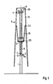
- the standing umbrella shown consists essentially of the telescopic mast (1-3), which is formed by the tubular mast (1) and the telescopic rod (3) displaceable in it by an adjusting device (2), the umbrella linkage (4) and a clutch (5 ).
- the parts (1) to (5) initially form a structural unit.
- the telescopic rod (3) is again tubular, closed at the bottom with an end wall (7) having a nut thread (6) and closed at the top by a cover plate of the first bearing ring (8).
- a threaded spindle (9) engages in the nut thread (6) of the end wall (7) and sits inside the tubular mast (1) in an angular gear (10) which is actuated by a hand crank (11).
- the threaded spindle (9) has a catchy, self-locking trapezoidal thread with a moderate pitch of e.g. 4 mm. There is therefore no need for self-locking in the angular gear (10), which is normally operated by a hand crank (11) and has a pair of bevel gears (12).
- the top of the gear housing (13) can also be used as a stop for the end wall (7) of the telescopic rod (3) or to define the lower holder of the umbrella frames in the rest position Fig. 1.
- the first bearing ring (8) can be raised by cranking the spindle (9) and thus the telescopic rod (3).
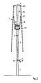
- the configuration of the umbrella rod remains unchanged, the roof rods (15) hang in their bearings (26) and a second bearing ring (17) is connected to the struts (19) via lower joints (25) and hangs with them in the Joints (30) on the roof bars (15).
- the upper end of the mast (1) is firmly locked to the second bearing collar (17) via the clutch (5).
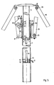
- This clutch is best seen in Fig. (5a).
- a bearing ring (18) with a Z-shaped cross section is welded to the upper end of the tubular mast (1), on which a lever bearing (16) for a triangular plate-shaped locking lever (29) is attached close to the telescopic rod (3).
- the hanging locking lever (29) has a radially widely projecting weight part (30) and, according to FIG. 5 a, engages with a lower locking lug (21) under the outer flange (22) of a coupling sleeve (23), which is mounted on the outer tube by means of bearing bushes (24) (1) guided and firmly connected to the disc-shaped part of the second bearing ring (17).
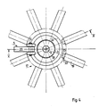
- the movement space for the unlocking ring (32) is limited by stop lugs (33) attached to the inside of expansion struts (19).
- the unlocking ring (32) lies between the two stop surfaces (34) of the locking lever (29) and (35) of the stop lugs (33).
- the locking lug (21) is at a distance (a) from the coupling sleeve (23).
- the clutch (5) is open, and the unlocking ring (32) is freely adjustable on the base flange (27) of the bearing ring (18).
- the upper edges of the two stop lugs (33) bump under one edge of the unlocking ring (32) and lift it unilaterally.
- the upper edge of the outer flange (22) of the coupling sleeve (23) runs against the inclined surface (14) of the locking lug (21), which then clicks under the restoring moment from the weight part (30) under the outer flange (22).
- the outer mast (1) as a whole or the lower bearing rim (17) can optionally be provided with adjustable height relative to the main mast. If you leave the entire setting device (2) unchanged, the height difference, parking position and rest position are also retained. Only the height of the two end positions of the lower bearing ring (17) changes in the same direction.
- the telescopic rod (3) is first extended again by means of the hand crank (11) in the transmission used here and the umbrella rod is folded up shortly before reaching the park position Fig. 2.
Landscapes
- Walking Sticks, Umbrellas, And Fans (AREA)
- Power-Operated Mechanisms For Wings (AREA)
Applications Claiming Priority (2)
| Application Number | Priority Date | Filing Date | Title |
|---|---|---|---|
| DE19883830328 DE3830328A1 (de) | 1988-09-07 | 1988-09-07 | Standschirm mit teleskopmast |
| DE3830328 | 1988-09-07 |
Publications (2)
| Publication Number | Publication Date |
|---|---|
| EP0358043A2 true EP0358043A2 (fr) | 1990-03-14 |
| EP0358043A3 EP0358043A3 (fr) | 1991-02-27 |
Family
ID=6362414
Family Applications (1)
| Application Number | Title | Priority Date | Filing Date |
|---|---|---|---|
| EP19890115512 Withdrawn EP0358043A3 (fr) | 1988-09-07 | 1989-08-23 | Parasol sur pied avec manche téléscopique |
Country Status (2)
| Country | Link |
|---|---|
| EP (1) | EP0358043A3 (fr) |
| DE (1) | DE3830328A1 (fr) |
Cited By (2)
| Publication number | Priority date | Publication date | Assignee | Title |
|---|---|---|---|---|
| WO2005039346A1 (fr) * | 2003-09-26 | 2005-05-06 | Uhlmann Sonnenschirme | Dispositif parasol a plate-forme abaissable pour des radiateurs chauffants |
| US7562666B2 (en) * | 2006-07-27 | 2009-07-21 | Chiaphua Components Limited | Motorized umbrella |
Family Cites Families (4)
| Publication number | Priority date | Publication date | Assignee | Title |
|---|---|---|---|---|
| USRE24477E (en) * | 1955-03-14 | 1958-05-27 | Beach and garden umbrella and mechanism for | |
| US2937653A (en) * | 1957-03-04 | 1960-05-24 | Calpatio Co Inc | Supporting and release catch for umbrella runners |
| DE2533049A1 (de) * | 1975-07-24 | 1977-02-10 | Carl Becher Ohg Planen U Zelte | Standschirm |
| US4424824A (en) * | 1982-07-20 | 1984-01-10 | Becher Textil- Und Stahlbau Gmbh | Garden and market umbrella |
-
1988
- 1988-09-07 DE DE19883830328 patent/DE3830328A1/de not_active Withdrawn
-
1989
- 1989-08-23 EP EP19890115512 patent/EP0358043A3/fr not_active Withdrawn
Cited By (2)
| Publication number | Priority date | Publication date | Assignee | Title |
|---|---|---|---|---|
| WO2005039346A1 (fr) * | 2003-09-26 | 2005-05-06 | Uhlmann Sonnenschirme | Dispositif parasol a plate-forme abaissable pour des radiateurs chauffants |
| US7562666B2 (en) * | 2006-07-27 | 2009-07-21 | Chiaphua Components Limited | Motorized umbrella |
Also Published As
| Publication number | Publication date |
|---|---|
| EP0358043A3 (fr) | 1991-02-27 |
| DE3830328A1 (de) | 1990-03-08 |
Similar Documents
| Publication | Publication Date | Title |
|---|---|---|
| DE60212132T2 (de) | Stabilisator mit teleskopstangen für dreibeine | |
| DE69925001T2 (de) | Aufrichtbarer unterstand mit zusammenlegbarer zentraldachunterstützung | |
| DE3043465C2 (de) | Sonnenschirm | |
| EP0526615B1 (fr) | Parasol, notamment parasol de grande taille | |
| DE8126081U1 (de) | Gartenschirm | |
| DE2233645A1 (de) | Schirm | |
| DE1248246B (de) | Verkuerzbarer Schirm | |
| EP0358043A2 (fr) | Parasol sur pied avec manche téléscopique | |
| DE8114991U1 (de) | Arbeitsstisch | |
| DE2712627B2 (de) | Betätigungsvorrichtung für einen Großschirm | |
| DE2649849C3 (de) | Bodenluke mit zusammenklappbarer Leiter | |
| DE3416889A1 (de) | Vorrichtung zum ausbreiten und einziehen einer schutzplane | |
| DE2809850C2 (de) | Teleskopartige Stützvorrichtung, insbesondere für Drehstühle | |
| DE2331072C3 (de) | Hubschrauber | |
| DE8713978U1 (de) | Standschirm | |
| DE3136357C2 (fr) | ||
| DE102006002184A1 (de) | Verfahren zum motorischen Anheben eines Scherenpodestes, Scherenpodest zum Aufbau einer Bühne oder eines Podiums, sowie Nachrüstsatz für ein Scherenpodest | |
| DE19932558C2 (de) | Stuhl, insbesondere Bürodrehstuhl | |
| DE19519034C2 (de) | Schirm, insbesondere Standschirm | |
| WO1992014377A1 (fr) | Parasol | |
| DE4013331C1 (en) | Clamp for telescopic column in gymnasium - incorporates collar with levers engaging holes in hollow column | |
| DE4443909A1 (de) | Schirmhalter | |
| DE2533049A1 (de) | Standschirm | |
| DE4026450A1 (de) | Standschirm | |
| EP0803209A2 (fr) | Armature pour parasol de grande taille |
Legal Events
| Date | Code | Title | Description |
|---|---|---|---|
| PUAI | Public reference made under article 153(3) epc to a published international application that has entered the european phase |
Free format text: ORIGINAL CODE: 0009012 |
|
| AK | Designated contracting states |
Kind code of ref document: A2 Designated state(s): AT CH DE ES FR GB IT LI |
|
| PUAL | Search report despatched |
Free format text: ORIGINAL CODE: 0009013 |
|
| AK | Designated contracting states |
Kind code of ref document: A3 Designated state(s): AT CH DE ES FR GB IT LI |
|
| RHK1 | Main classification (correction) |
Ipc: A45B 25/14 |
|
| 17P | Request for examination filed |
Effective date: 19910725 |
|
| 17Q | First examination report despatched |
Effective date: 19930312 |
|
| STAA | Information on the status of an ep patent application or granted ep patent |
Free format text: STATUS: THE APPLICATION IS DEEMED TO BE WITHDRAWN |
|
| 18D | Application deemed to be withdrawn |
Effective date: 19930723 |