EP0358043A2 - Sun shade with a base and a telescopic mast - Google Patents
Sun shade with a base and a telescopic mast Download PDFInfo
- Publication number
- EP0358043A2 EP0358043A2 EP89115512A EP89115512A EP0358043A2 EP 0358043 A2 EP0358043 A2 EP 0358043A2 EP 89115512 A EP89115512 A EP 89115512A EP 89115512 A EP89115512 A EP 89115512A EP 0358043 A2 EP0358043 A2 EP 0358043A2
- Authority
- EP
- European Patent Office
- Prior art keywords
- umbrella
- mast
- bearing ring
- closed
- bearing
- Prior art date
- Legal status (The legal status is an assumption and is not a legal conclusion. Google has not performed a legal analysis and makes no representation as to the accuracy of the status listed.)
- Withdrawn
Links
Images


Classifications
-
- A—HUMAN NECESSITIES
- A45—HAND OR TRAVELLING ARTICLES
- A45B—WALKING STICKS; UMBRELLAS; LADIES' OR LIKE FANS
- A45B19/00—Special folding or telescoping of umbrellas
- A45B19/04—Special folding or telescoping of umbrellas with telescopic sticks
-
- A—HUMAN NECESSITIES
- A45—HAND OR TRAVELLING ARTICLES
- A45B—WALKING STICKS; UMBRELLAS; LADIES' OR LIKE FANS
- A45B23/00—Other umbrellas
-
- A—HUMAN NECESSITIES
- A45—HAND OR TRAVELLING ARTICLES
- A45B—WALKING STICKS; UMBRELLAS; LADIES' OR LIKE FANS
- A45B25/00—Details of umbrellas
- A45B25/02—Umbrella frames
-
- A—HUMAN NECESSITIES
- A45—HAND OR TRAVELLING ARTICLES
- A45B—WALKING STICKS; UMBRELLAS; LADIES' OR LIKE FANS
- A45B25/00—Details of umbrellas
- A45B25/14—Devices for opening and for closing umbrellas
-
- A—HUMAN NECESSITIES
- A45—HAND OR TRAVELLING ARTICLES
- A45B—WALKING STICKS; UMBRELLAS; LADIES' OR LIKE FANS
- A45B23/00—Other umbrellas
- A45B2023/0012—Ground supported umbrellas or sunshades on a single post, e.g. resting in or on a surface there below
-
- A—HUMAN NECESSITIES
- A45—HAND OR TRAVELLING ARTICLES
- A45B—WALKING STICKS; UMBRELLAS; LADIES' OR LIKE FANS
- A45B25/00—Details of umbrellas
- A45B25/14—Devices for opening and for closing umbrellas
- A45B2025/146—Devices for opening and for closing umbrellas with a crank connected to a rope
Definitions
- the invention relates to a standing umbrella with a telescopic mast, which, like hand-held umbrellas, serves the opening and closing process there and / or is used to adjust the height of the umbrella.
- a standing umbrella with a movable in the longitudinal direction of the mast first bearing ring is known for the roof poles supporting a screen skin, which are supported by a spreading gear with a second bearing ring by struts on the mast and through these struts between the clamping position, Allow the closing and envelope positions to move over a medium clamping position.
- the umbrella is opened or closed and simultaneously raised or lowered by an actuating operation in the same direction.
- the opening position is predetermined by the respective lifting position of the umbrella rod. This contradicts the different requirements of the numerous users.
- the invention is based on the umbrella construction defined at the outset and pursues the task of developing this known umbrella in such a way that its operation is simplified and at least the completely closed umbrella can be brought to different altitudes without changing its closed position and can be opened and closed by reversing the drive when the actuating process is directed in the same direction .
- the triggering device to be actuated by means of the adjusting device or the umbrella rod depending on the direction of movement thereof Bracket of the second bearing ring on the outer mast.
- the second bearing ring can be fixed on the mast, with the reverse movement for closing the screen from the open position, this connection can be released again without any additional operations having to be carried out.
- the actuating device is actuated, for example by means of a crank or by a motor drive in one direction and then in the other.
- the opening or closing movement can be carried out with a lowering or lifting process. It is important, however, that the screen cannot carry out any uncontrolled lowering or closing processes during all operating processes.
- This protection serves, among other things. the self-locking support by the adjusting device or the umbrella rod.
- at least one of the two brackets is arranged at a predetermined height. In principle, however, both brackets can be set to be adjustable in height in order to meet the different requirements.
- a releasable tensioning or locking device is preferably assigned to the clutch.
- the height setting of this bearing ring then determines the height of the canopy regardless of its unfolded state.
- a bolt which is attached to the tubular mast and operates in the closing direction with a bolt nose engages behind a projection on the lower bearing ring.
- This bearing ring is thereby at the respective height, preferably at the upper end of the The outer mast is locked, clamped or fixed in some other way, so that the deployment or tensioning path along the mast is predetermined from there.
- the projection of the second bearing ring can be formed by an annular flange projecting outwards from the upper end of a projecting coupling sleeve. This has the advantage that the locking or tensioning of the canopy to the mast base can be carried out in any relative rotational position without changing the function.
- the release device has an unlocking element which projects directly or indirectly into the path of a movable part of the umbrella rod and which acts directly or indirectly on part of the clutch.
- an actuating element can be provided opposite a coupling element and a release element, in particular an unlocking ring, can be arranged between the tubular mast.
- Such a trigger element can primarily be moved radially to the tubular mast, for which purpose, for example, a guide flange attached to the tubular mast or to the bearing ring can be used, which is preferably arranged closely above the outer flange of the lower bearing ring.
- the outer dimension of the unlocking or triggering element should be as much as possible greater than the clear width between the locking element and the opposite actuation element or elements in the closed position of the screen.
- the release element can be tilted upward from its support plane by lifting it on one side by means of at least one actuating member in order to prepare the unlocking process.
- the unlocking element can be attached between the actuating elements and a locking element in such a way that after reversal of the movement of the telescopic rod, the bolt can be triggered by the unlocking element by means of one or more actuating elements.
- An expansion strut can be used as the actuating element, preferably two, which have a nose with a surface that is approximately axially parallel in the closed state.
- the standing umbrella shown consists essentially of the telescopic mast (1-3), which is formed by the tubular mast (1) and the telescopic rod (3) displaceable in it by an adjusting device (2), the umbrella linkage (4) and a clutch (5 ).
- the parts (1) to (5) initially form a structural unit.
- the telescopic rod (3) is again tubular, closed at the bottom with an end wall (7) having a nut thread (6) and closed at the top by a cover plate of the first bearing ring (8).
- a threaded spindle (9) engages in the nut thread (6) of the end wall (7) and sits inside the tubular mast (1) in an angular gear (10) which is actuated by a hand crank (11).
- the threaded spindle (9) has a catchy, self-locking trapezoidal thread with a moderate pitch of e.g. 4 mm. There is therefore no need for self-locking in the angular gear (10), which is normally operated by a hand crank (11) and has a pair of bevel gears (12).
- the top of the gear housing (13) can also be used as a stop for the end wall (7) of the telescopic rod (3) or to define the lower holder of the umbrella frames in the rest position Fig. 1.
- the first bearing ring (8) can be raised by cranking the spindle (9) and thus the telescopic rod (3).
- the configuration of the umbrella rod remains unchanged, the roof rods (15) hang in their bearings (26) and a second bearing ring (17) is connected to the struts (19) via lower joints (25) and hangs with them in the Joints (30) on the roof bars (15).
- the upper end of the mast (1) is firmly locked to the second bearing collar (17) via the clutch (5).
- This clutch is best seen in Fig. (5a).
- a bearing ring (18) with a Z-shaped cross section is welded to the upper end of the tubular mast (1), on which a lever bearing (16) for a triangular plate-shaped locking lever (29) is attached close to the telescopic rod (3).
- the hanging locking lever (29) has a radially widely projecting weight part (30) and, according to FIG. 5 a, engages with a lower locking lug (21) under the outer flange (22) of a coupling sleeve (23), which is mounted on the outer tube by means of bearing bushes (24) (1) guided and firmly connected to the disc-shaped part of the second bearing ring (17).
- the movement space for the unlocking ring (32) is limited by stop lugs (33) attached to the inside of expansion struts (19).
- the unlocking ring (32) lies between the two stop surfaces (34) of the locking lever (29) and (35) of the stop lugs (33).
- the locking lug (21) is at a distance (a) from the coupling sleeve (23).
- the clutch (5) is open, and the unlocking ring (32) is freely adjustable on the base flange (27) of the bearing ring (18).
- the upper edges of the two stop lugs (33) bump under one edge of the unlocking ring (32) and lift it unilaterally.
- the upper edge of the outer flange (22) of the coupling sleeve (23) runs against the inclined surface (14) of the locking lug (21), which then clicks under the restoring moment from the weight part (30) under the outer flange (22).
- the outer mast (1) as a whole or the lower bearing rim (17) can optionally be provided with adjustable height relative to the main mast. If you leave the entire setting device (2) unchanged, the height difference, parking position and rest position are also retained. Only the height of the two end positions of the lower bearing ring (17) changes in the same direction.
- the telescopic rod (3) is first extended again by means of the hand crank (11) in the transmission used here and the umbrella rod is folded up shortly before reaching the park position Fig. 2.
Landscapes
- Walking Sticks, Umbrellas, And Fans (AREA)
- Power-Operated Mechanisms For Wings (AREA)
Abstract
Durch einen gleichgerichteten Betätigungsvorgang wird ein Standschirm ohne Änderung seiner Schließstellung auf verschiedene Höhenlagen gebracht und durch Antriebsumkehr geöffnet und geschlossen. Im Rohrmast (1) ist mittels einer Stellvorrichtung (11,12) ein Teleskopstab (3) verschiebbar geführt, dessen oberes Ende einen Lagerkranz (8) trägt, an dem die Schließstangen (15) aufgehängt sind. Sein unteres Ende ist durch eine Stirnwand (7) verschlossen, in deren Muttergewinde (6) selbsthemmend eine durch eine Kurbel (11) drehbare Gewindespindel (9) eingreift. Ein Lagerkranz (17) ist höheneinstellbar auf dem Rohrmast (1) geführt und durch eine Schaltkupplung (5) an diesem festlegbar. Bei geschlossener Kupplung wird durch die Spindel (9) der Abstand zwischen den Lagerkränzen (8,17) verändert, also der Schirm geöffnet oder geschlossen. Bei etwa kleinstem Öffnungswinkel der Dachstangen (15) wird die Schaltkupplung (5) selbsttätig geöffnet. Dann kann der Schirm ohne Änderung seiner Schließstellung gehoben und gesenkt werden. Da auch der Schließvorgang selbsttätig gesteuert wird, läßt sich ein Änderungszyklus im Öffnungs- und Hubbereich selbsttätig durch Heben oder Senken des ersten Lagerkranzes (8) steuern, was die Bedienung vereinfacht und die Bedienungssicherheit erhöht. 
Description
Die Erfindung betrifft einen Standschirm mit Teleskopmast, der dort ebenso wie bei Handschirmen dem Öffnungs- und Schließvorgang dient und/oder zur Höheneinstellung des Schirmes verwendet wird.The invention relates to a standing umbrella with a telescopic mast, which, like hand-held umbrellas, serves the opening and closing process there and / or is used to adjust the height of the umbrella.
Durch die DE-PS 31 36 357 ist ein Standschirm mit einem in Längsrichtung des Mastes bewegbaren ersten Lagerkranz für die eine Schirmhaut tragenden Dachstangen bekannt, die durch ein Spreizgetriebe mit einem zweiten Lagerkranz durch Streben am Mast abgestützt sind und sich durch diese Streben zwischen Spannstellung, Schliesstellung und Hüllstellung über eine mittlere Spannstellung hinweg bewegen lassen. Auf diese Weise wird durch einen gleichgerichteten Betätigungsvorgang der Schirm geöffnet oder geschlossen und gleichzeitig gehoben oder gesenkt. Dabei und bei anderen bekannten Schirmkonstruktionen ist so die Öffnungslage durch die jeweilige Hubstellung des Schirmgestänges vorgegeben. Dies widerspricht den unterschiedlichen Anforderungen der zahlreicher Benutzer.From DE-PS 31 36 357 a standing umbrella with a movable in the longitudinal direction of the mast first bearing ring is known for the roof poles supporting a screen skin, which are supported by a spreading gear with a second bearing ring by struts on the mast and through these struts between the clamping position, Allow the closing and envelope positions to move over a medium clamping position. In this way, the umbrella is opened or closed and simultaneously raised or lowered by an actuating operation in the same direction. In this case and in other known umbrella constructions, the opening position is predetermined by the respective lifting position of the umbrella rod. This contradicts the different requirements of the numerous users.
Bekannt ist zwar durch die französische Patentschrift 12 93 790 ein Marktschirm mit einem einstückigen Mast, auf dem zwei lotrecht einstellbare Buchsen mit Lagerkränzen ver schiebbar und feststellbar angebracht sind. Auf diese Weise kann zwar grundsätzlich jede Schirmöffnung in jeder durch die Mastlänge ermöglichten Höhe eingestellt werden. Die Bedienung ist jedoch außerordentlich mühsam, so daß sich Schirme dieser Art nicht mehr haben halten können.Although it is known from the
Erfindung geht aus von der eingangs definierten Schirmkonstruktion und verfolgt die Aufgabe, diesen bekannten Schirm so weiterzubilden, daß seine Bedienung vereinfacht und bei gleichgerichtetem Betätigungsvorgang wenigstens der völlig geschlossene Schirm ohne Änderung seiner Schliesstellung auf verschiedene Höhenlagen gebracht werden kann und sich durch Antriebsumkehr öffnen und schließen läßt.The invention is based on the umbrella construction defined at the outset and pursues the task of developing this known umbrella in such a way that its operation is simplified and at least the completely closed umbrella can be brought to different altitudes without changing its closed position and can be opened and closed by reversing the drive when the actuating process is directed in the same direction .
Zur Lösung dieser Aufgabe dient erfindungsgemäß ein Standschirm mit folgenden Merkmalen:
- a) in einem Rohrmast ist durch eine Stellvorrichtung verschiebbar ein Teleskopmast geführt,
- b) der fest einen ersten Lagerkranz für in diesem schwenkbare Dachstangen des selbsthemmend abgestützten Schirmgestänges trägt;
- c) die Dachstangen sind durch Spreizstreben abgestützt, die in einem am Rohrmast lotrecht verschiebbaren zweiten Lagerkranz gelagert sind,
- d) der am Rohrmast (1) durch eine Schaltkupplung an- und abkuppelbar ist,
- e) die mittels der Stellvorrichtung und/oder des Schirmgestänges in vorgegebener Folge innerhalb eines Verstellzyklus zu öffnen und zu schließen ist.
- a) a telescopic mast is slidably guided in a tubular mast by an adjusting device,
- b) which carries a first bearing ring for the self-locking umbrella linkage in this pivotable roof rods;
- c) the roof poles are supported by expansion struts which are mounted in a second bearing ring which can be displaced vertically on the tubular mast,
- d) which can be connected and disconnected from the tubular mast (1) by means of a clutch,
- e) which is to be opened and closed in a predetermined sequence within an adjustment cycle by means of the adjusting device and / or the screen linkage.
Bedeutsam ist hier vor allem die mittels der Stellvorrichtung oder des Schirmgestänges in Abhängigkeit von deren Bewegungsrichtung zu betätigene Auslösevorrichtung für die Halterung des zweiten Lagerkranzes am Außenmast. Bei einem Bewegungsvorgang, etwa zum Anheben in eine Parkstellung läßt sich so der zweite Lagerkranz am Mast festlegen, bei der umgekehrten Bewegung zum Schließen des Schirmes aus der Öffnungsstellung läßt sich diese Verbindung wieder lösen, ohne daß irgendwelche zusätzlichen Verrichtungen vorzunehmen sind.What is particularly important here is the triggering device to be actuated by means of the adjusting device or the umbrella rod depending on the direction of movement thereof Bracket of the second bearing ring on the outer mast. During a movement process, for example for lifting into a parking position, the second bearing ring can be fixed on the mast, with the reverse movement for closing the screen from the open position, this connection can be released again without any additional operations having to be carried out.
Man betätigt eben die Stellvorrichtung, etwa mittels einer Kurbel oder durch einen motorischen Antrieb in der einen Richtung und dann in der anderen. Dabei kann je nach Auslegung der Stellvorrichtung und des Schirmgestänges die Öffnungs- oder Schließbewegung mit einem Senk- oder Hubvorgang durchgeführt werden. Bedeutsam ist jedoch, daß der Schirm während aller Betriebsvorgänge keine unkontrollierten Senk- oder Schließvorgänge ausführen kann. Dieser Absicherung dient u.a. die selbsthemmende Abstützung durch die Stellvorrichtung oder das Schirmgestänge. In der Regel wird zwar wenigstens eine der beiden Halterungen, meist die untere, in einer fest vorgegebenen Höhenlage angeordnet. Grundsätzlich lassen sich jedoch beide Halterungen höheneinstellbar einrichten, um den unterschiedlichen Anforderungen zu genügen.The actuating device is actuated, for example by means of a crank or by a motor drive in one direction and then in the other. Depending on the design of the adjusting device and the umbrella rod, the opening or closing movement can be carried out with a lowering or lifting process. It is important, however, that the screen cannot carry out any uncontrolled lowering or closing processes during all operating processes. This protection serves, among other things. the self-locking support by the adjusting device or the umbrella rod. As a rule, at least one of the two brackets, usually the lower one, is arranged at a predetermined height. In principle, however, both brackets can be set to be adjustable in height in order to meet the different requirements.
Vorzugsweise wird der Schaltkupplung eine lösbare Spann- oder Riegeleinrichtung zugeordnet. Die Höheneinstellung dieses Lagerkranzes bestimmt dann die Höhe des Schirmdaches unabhängig von seinem Entfaltungszustand.A releasable tensioning or locking device is preferably assigned to the clutch. The height setting of this bearing ring then determines the height of the canopy regardless of its unfolded state.
Bei einer bevorzugten Ausführungsform der Erfindung hintergreift z.B. ein am Rohrmast angebrachter und im Schließsinn kraftbetätigender Riegel mit einer Riegelnase einen Vorsprung am unteren Lagerkranz. Dieser Lagerkranz wird dadurch in der jeweiligen Höhe, vorzugsweise am oberen Ende des Außenmastes fest verriegelt, verspannt oder auf andere Weise festgelegt, so daß von dort der Entfaltungs- oder Spannweg längs des Mastes vorgegeben ist.In a preferred embodiment of the invention, for example, a bolt which is attached to the tubular mast and operates in the closing direction with a bolt nose engages behind a projection on the lower bearing ring. This bearing ring is thereby at the respective height, preferably at the upper end of the The outer mast is locked, clamped or fixed in some other way, so that the deployment or tensioning path along the mast is predetermined from there.
Dabei kann der Vorsprung des zweiten Lagerkranzes durch einen vom oberen Ende einer hochragenden Kupplungshülse nach außen ragenden Ringflansch gebildet sein. Dies hat den Vorteil, daß sich die Verriegelung oder Verspannung des Schirmdaches zum Mastfuß in jeder Relativ-Drehlage ohne Funktionsänderung durchführen läßt.The projection of the second bearing ring can be formed by an annular flange projecting outwards from the upper end of a projecting coupling sleeve. This has the advantage that the locking or tensioning of the canopy to the mast base can be carried out in any relative rotational position without changing the function.
Als zweckmäßig hat sich hier erwiesen, wenn die Auslösevorrichtung ein mittelbar oder unmittelbar in die Bahn eines bewegbaren Teiles des Schirmgestänges vorragendes Entriegelungselement aufweist, das mittelbar oder unmittelbar auf ein Teil der Schaltkupplung einwirkt.It has proven to be expedient here if the release device has an unlocking element which projects directly or indirectly into the path of a movable part of the umbrella rod and which acts directly or indirectly on part of the clutch.
So kann ein Betätigungselement einem Kupplungselement gegenüberliegend vorgesehen sein und zwischen ihnen ein den Rohrmast umgreifendes Auslöseelement, insbesondere ein Entriegelungsring angeordnet werden.For example, an actuating element can be provided opposite a coupling element and a release element, in particular an unlocking ring, can be arranged between the tubular mast.
Ein solches Auslöseelement läßt sich vornehmlich radial zum Rohrmast bewegbar führen, wozu beispielsweise ein am Rohrmast bzw. am Lagerring angebrachter Führungsflansch dienen kann, der vorzugsweise dicht über dem Außenflansch des unteren Lagerkranzes angeordnet ist.Such a trigger element can primarily be moved radially to the tubular mast, for which purpose, for example, a guide flange attached to the tubular mast or to the bearing ring can be used, which is preferably arranged closely above the outer flange of the lower bearing ring.
Die Außenabmessung des Entriegelungs- bzw. Auslöseelementes sollte dabei möglichst etwas größer sein als die lichte Weite zwischen dem Riegelelement und dem oder den gegenüberliegenden Betätigungselementen in der Schließstellung des Schirms.The outer dimension of the unlocking or triggering element should be as much as possible greater than the clear width between the locking element and the opposite actuation element or elements in the closed position of the screen.
So läßt sich das Auslöseelement durch einseitiges Anheben mittels wenigstens eines Betätigungsorgans aus seiner Auflageebene nach schräg oben aufkippbar vorsehen, um den Entriegelungsvorgang vorzubereiten. Andererseits kann bei leichtem Öffnen des Schirmes das Entriegelungselement so zwischen den Betätigungselementen und einem Riegelelement angebracht werden, daß nach Bewegungsumkehr des Teleskopstabes der Riegel durch das Entriegelungselement mittels eines oder mehrerer Betätigungselemente ausgelöst werden kann.For example, the release element can be tilted upward from its support plane by lifting it on one side by means of at least one actuating member in order to prepare the unlocking process. On the other hand, with a slight opening of the screen, the unlocking element can be attached between the actuating elements and a locking element in such a way that after reversal of the movement of the telescopic rod, the bolt can be triggered by the unlocking element by means of one or more actuating elements.
Als Betätigungselement kann eine Spreizstrebe dienen, vorzugsweise zwei, die eine Nase mit einer im Schließzustand etwa achsparallele Fläche aufweisen.An expansion strut can be used as the actuating element, preferably two, which have a nose with a surface that is approximately axially parallel in the closed state.
Weitere Ausgestaltungen und Vorteile der Erfindung sind in den Unteransprüchen herausgestellt und sollen nun anhand der Zeichnung ausführlicher erläutert werden. Es zeigen:
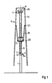
- Fig. 1 in schematischer Darstellung einen erfindungsgemäßen Standschirm, zusammengefaltet und in der tiefsten Stellung, der "Ruhestellung"
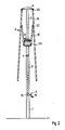
- Fig. 2 diesen Standschirm in der gleichen Faltstellung bis zur oberen Endstellung, der "Parkstellung", ausgefahren,
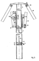
- Fig. 3 den aus der Parkstellung Fig. 2 in die "Schirmstellung" aufgespannten Standschirm,
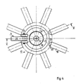
- Fig. 4 eine vergrößerte Auszugsdarstellung des Schirmmastes, teilweise entlang der Linie IV-IV in Fig. 3 geschnitten,
- Fig. 5 einen in Sektionen verkürzten Längsschnitt nach der Linie V-V nach Fig. 4, jedoch mit dem Schirmgestänge in der Schließstellung nach Fig. 2, und
- Fig.5a eine weiter vergrößerte Einzelheit aus Fig. 5
- 1 is a schematic representation of a parachute according to the invention, folded and in the lowest position, the "rest position"
- 2 extended this parachute in the same folded position up to the upper end position, the "parking position",
- 3 the standing umbrella stretched from the parking position FIG. 2 into the "umbrella position",
- 4 is an enlarged view of an excerpt from the umbrella mast, partially cut along the line IV-IV in FIG. 3,
- Fig. 5 is a sectioned longitudinal section along the line VV of FIG. 4, but with the umbrella linkage in the closed position of FIG. 2, and
- 5a shows a further enlarged detail from FIG. 5
Der dargestellte Standschirm besteht im wesentlichen aus dem Teleskopmast (1-3), der durch den Rohrmast (1) und den in diesem durch eine Stellvorrichtung (2) verschiebbaren Teleskopstab (3) gebildet wird, dem Schirmgestänge (4) und einer Schaltkupplung (5).The standing umbrella shown consists essentially of the telescopic mast (1-3), which is formed by the tubular mast (1) and the telescopic rod (3) displaceable in it by an adjusting device (2), the umbrella linkage (4) and a clutch (5 ).
Dabei bilden zunächst die Teile (1) bis (5) eine bauliche Einheit. Der Teleskopstab (3) ist wiederum rohrförmig ausgebildet, unten mit einer ein Muttergewinde (6) aufweisenden Stirnwand (7) und oben durch eine Deckscheibe des ersten Lagerkranzes (8) verschlossen.The parts (1) to (5) initially form a structural unit. The telescopic rod (3) is again tubular, closed at the bottom with an end wall (7) having a nut thread (6) and closed at the top by a cover plate of the first bearing ring (8).
In das Muttergewinde (6) der Stirnwand (7) greift eine Gewindespindel (9), die innerhalb des Rohrmastes (1) in einem Winkelgetriebe (10) sitzt, das durch eine Handkurbel (11) betätigt wird.A threaded spindle (9) engages in the nut thread (6) of the end wall (7) and sits inside the tubular mast (1) in an angular gear (10) which is actuated by a hand crank (11).
Die Gewindespindel (9) hat ein eingängiges selbsthemmendes Trapezgewinde mit mäßiger Steigung von z.B. 4 mm. Daher erübrigt sich eine Selbsthemmung bei dem Winkelgetriebe (10), das normalerweise durch eine Handkurbel (11) betrieben wird und ein Kegelradpaar (12) aufweist.The threaded spindle (9) has a catchy, self-locking trapezoidal thread with a moderate pitch of e.g. 4 mm. There is therefore no need for self-locking in the angular gear (10), which is normally operated by a hand crank (11) and has a pair of bevel gears (12).
Die Oberseite des Getriebegehäuses (13) kann zudem als Anschlag für die Stirnwand (7) des Teleskopstabes (3) bzw. zur Definition der unteren Halterung des Schirmgestelle in der Ruhestellung Fig. 1 herangezogen werden. Durch Hochkurbeln der Spindel (9) und damit des Teleskopstabes (3) kann der erste Lagerkranz (8) hochgefahren werden. Die Konfiguration des Schirmgestänges bleibt dabei unverändert, die Dachstangen (15) hängen in ihren Lagern (26) und ein zweiter Lagerkranz (17) ist über untere Gelenke (25) an die Spreizstreben (19) angeschlossen und hängt mit diesen in den Gelenken (30) an den Dachstangen (15). Dabei ist das obere Ende des Rohrmastes (1) über die Schaltkupplung (5) fest mit dem zweiten Lagerkranz (17) verriegelt.The top of the gear housing (13) can also be used as a stop for the end wall (7) of the telescopic rod (3) or to define the lower holder of the umbrella frames in the rest position Fig. 1. The first bearing ring (8) can be raised by cranking the spindle (9) and thus the telescopic rod (3). The configuration of the umbrella rod remains unchanged, the roof rods (15) hang in their bearings (26) and a second bearing ring (17) is connected to the struts (19) via lower joints (25) and hangs with them in the Joints (30) on the roof bars (15). The upper end of the mast (1) is firmly locked to the second bearing collar (17) via the clutch (5).
Diese Schaltkupplung ist am besten aus Fig. (5a) zu ersehen. Dort ist am oberen Ende des Rohrmastes (1) ein im Querschnitt Z-förmiger Lagerring (18) aufgeschweißt, an dem dicht am Teleskopstab (3) ein Hebellager (16) für einen dreieckplattenförmigen Riegelhebel (29) angebracht ist.This clutch is best seen in Fig. (5a). There, a bearing ring (18) with a Z-shaped cross section is welded to the upper end of the tubular mast (1), on which a lever bearing (16) for a triangular plate-shaped locking lever (29) is attached close to the telescopic rod (3).
Der hängende Riegelhebel (29) hat einen radial weit ausladenden Gewichtsteil (30) und greift nach Fig. 5 a mit einer unteren Riegelnase (21) unter den Außenflansch (22) einer Kupplungshülse (23), die mittels Lagerbuchsen (24) auf dem Außenrohr (1) geführt und mit dem scheibenförmigen Teil des zweiten Lagerkranzes (17) fest verbunden ist.The hanging locking lever (29) has a radially widely projecting weight part (30) and, according to FIG. 5 a, engages with a lower locking lug (21) under the outer flange (22) of a coupling sleeve (23), which is mounted on the outer tube by means of bearing bushes (24) (1) guided and firmly connected to the disc-shaped part of the second bearing ring (17).
In der Bügelhöhlung (31) des Riegelhebels (29) liegt auf dem Fußflansch (27) ein flacher, den Lagerring (18) umgebenden Entriegelungsring (32).A flat unlocking ring (32) surrounding the bearing ring (18) lies on the foot flange (27) in the bow cavity (31) of the locking lever (29).
Auf der rechten Seite in Fig. 5a ist der Bewegungsraum für den Entriegelungsring (32) begrenzt durch an der Innenseite von Spreizstreben (19) angebrachte Anschlagnasen (33). Der Entriegelungsring (32) liegt zwischen den beiden Anschlagflächen (34) des Riegelhebels (29) und (35) der Anschlagnasen (33). Dabei hat die Riegelnase (21) einen Abstand (a) zur Kupplungshülse (23).On the right-hand side in FIG. 5 a, the movement space for the unlocking ring (32) is limited by stop lugs (33) attached to the inside of expansion struts (19). The unlocking ring (32) lies between the two stop surfaces (34) of the locking lever (29) and (35) of the stop lugs (33). The locking lug (21) is at a distance (a) from the coupling sleeve (23).
In der Ruhestellung nach Fig. 1 ist die Schaltkupplung (5) geöffnet, un der Entriegelungsring (32) liegt frei quereinstellbar auf dem Fußflansch (27) des Lagerringes (18). Dabei stossen zunächst die oberen Kanten der beiden Anschlagnasen (33) unter eine Kante des Entriegelungsringes (32) und heben diesen einseitig an. Etwa gleichzeitig läuft der obere Rand des Außenflansches (22) der Kupplungshülse (23) an der Schrägfläche (14) der Riegelnase (21) an, die anschließend unter dem Rückstellmoment aus dem Gewichtsteil (30) unter dem Außenflansch (22) einklinkt.In the rest position according to Fig. 1, the clutch (5) is open, and the unlocking ring (32) is freely adjustable on the base flange (27) of the bearing ring (18). First, the upper edges of the two stop lugs (33) bump under one edge of the unlocking ring (32) and lift it unilaterally. At approximately the same time, the upper edge of the outer flange (22) of the coupling sleeve (23) runs against the inclined surface (14) of the locking lug (21), which then clicks under the restoring moment from the weight part (30) under the outer flange (22).
Damit ist die Schaltkupplung geschlossen und der untere Lagerkranz (17) fest mit dem oberen Ende des Außenrohres verbunden.This closes the clutch and the lower bearing rim (17) is firmly connected to the upper end of the outer tube.
Beim anschließenden Rückwärtsdrehen der Kurbel (11) wird der Teleskopstab (3) und mit diesem der obere Lagerkranz (8) abgesenkt, und die Schrimstangen (15) werden durch die Spreizstreben (19) bis in die Schirmstellung Fig.3 nach außen geschwenkt.When the crank (11) is subsequently turned backwards, the telescopic rod (3) and with it the upper bearing ring (8) are lowered, and the trim rods (15) are pivoted outwards by the expansion struts (19) into the shield position Fig. 3.
Ebenso wie man die Parkstellung des Schirmes nach Fig.2 in allen Höhenlagen ab der Ruhestellung Fig. 1 beibehalten kann, gilt dies im Prinzip auch für die Öffnungsweite. Desgleichen kann gegebenenfalls auch der Außenmast (1) als Ganzes oder der untere Lagerkranz (17) gegenüber dem Hauptmast höheneinstellbar vorgesehen werden. Läßt man die ganze Stellvorrichtung (2) unverändert, so bleibt auch die Höhendifferenz, Parkstellung und Ruhestellung erhalten. Nur die Höhenlage der beiden Endstellungen des unteren Lagerkranzes (17) ändert sich gleichsinnig.Just as you can maintain the park position of the umbrella according to Fig. 2 at all altitudes from the rest position Fig. 1, this also applies in principle to the opening width. Likewise, the outer mast (1) as a whole or the lower bearing rim (17) can optionally be provided with adjustable height relative to the main mast. If you leave the entire setting device (2) unchanged, the height difference, parking position and rest position are also retained. Only the height of the two end positions of the lower bearing ring (17) changes in the same direction.
Zum Überführen des Schirmes aus der Schirmstellung Fig.3 in die Ruhestellung Fig.1 wird bei dem hier eingesetzten Getriebe mittels der Handkurbel (11) zunächst wieder die Teleskopstab (3) ausgefahren und dabei das Schirmgestänge kurz vor Erreichen der Parkstellung Fig.2 zusammengefaltet.To transfer the umbrella from the umbrella position Fig. 3 to the rest position Fig. 1, the telescopic rod (3) is first extended again by means of the hand crank (11) in the transmission used here and the umbrella rod is folded up shortly before reaching the park position Fig. 2.
Sobald dabei die Spreizstreben (19) einen Winkel von 9 bis 10 Grad zum Mast erreicht haben, schwenken die Anschlagnasen (33) mit ihren Anschlagflächen (35) gegen die Außenseite des Entriegelungsringes (32), der auf der gegenüberliegenden Seite den Riegelhebel (29) aufschwenkt und dadurch die Schaltkupplung (5) zum unteren Lagerkranz (17) löst. Da das ganze Schirmgestänge (4) noch am oberen Lagerkranz (8) hängt, fällt es jedoch nicht herab, sondern wird in unveränderter Lage über den Teleskopstab (3) durch die Selbsthemmung der Gewindespindel (9) weiterhin gehalten, bis die Ruhestellung Fig.1 erreicht ist.As soon as the struts (19) have reached an angle of 9 to 10 degrees to the mast, the stop lugs (33) pivot with their stop surfaces (35) against the outside of the unlocking ring (32), which on the opposite side has the locking lever (29) swings open and thereby releases the clutch (5) to the lower bearing rim (17). Since the whole umbrella rod (4) still hangs on the upper bearing rim (8), it does not fall down, but is held in the same position via the telescopic rod (3) by the self-locking of the threaded spindle (9) until the rest position Fig.1 is reached.
Claims (15)
Applications Claiming Priority (2)
| Application Number | Priority Date | Filing Date | Title |
|---|---|---|---|
| DE19883830328 DE3830328A1 (en) | 1988-09-07 | 1988-09-07 | STANDING UMBRELLA WITH TELESCOPIC MAST |
| DE3830328 | 1988-09-07 |
Publications (2)
| Publication Number | Publication Date |
|---|---|
| EP0358043A2 true EP0358043A2 (en) | 1990-03-14 |
| EP0358043A3 EP0358043A3 (en) | 1991-02-27 |
Family
ID=6362414
Family Applications (1)
| Application Number | Title | Priority Date | Filing Date |
|---|---|---|---|
| EP19890115512 Withdrawn EP0358043A3 (en) | 1988-09-07 | 1989-08-23 | Sun shade with a base and a telescopic mast |
Country Status (2)
| Country | Link |
|---|---|
| EP (1) | EP0358043A3 (en) |
| DE (1) | DE3830328A1 (en) |
Cited By (2)
| Publication number | Priority date | Publication date | Assignee | Title |
|---|---|---|---|---|
| WO2005039346A1 (en) * | 2003-09-26 | 2005-05-06 | Uhlmann Sonnenschirme | Sunshade device with a lowerable platform for radiant heaters |
| US7562666B2 (en) * | 2006-07-27 | 2009-07-21 | Chiaphua Components Limited | Motorized umbrella |
Family Cites Families (4)
| Publication number | Priority date | Publication date | Assignee | Title |
|---|---|---|---|---|
| USRE24477E (en) * | 1955-03-14 | 1958-05-27 | Beach and garden umbrella and mechanism for | |
| US2937653A (en) * | 1957-03-04 | 1960-05-24 | Calpatio Co Inc | Supporting and release catch for umbrella runners |
| DE2533049A1 (en) * | 1975-07-24 | 1977-02-10 | Carl Becher Ohg Planen U Zelte | Umberella cover for large outdoor area - has servo-motor moving spoke positioning tube in mast |
| US4424824A (en) * | 1982-07-20 | 1984-01-10 | Becher Textil- Und Stahlbau Gmbh | Garden and market umbrella |
-
1988
- 1988-09-07 DE DE19883830328 patent/DE3830328A1/en not_active Withdrawn
-
1989
- 1989-08-23 EP EP19890115512 patent/EP0358043A3/en not_active Withdrawn
Cited By (2)
| Publication number | Priority date | Publication date | Assignee | Title |
|---|---|---|---|---|
| WO2005039346A1 (en) * | 2003-09-26 | 2005-05-06 | Uhlmann Sonnenschirme | Sunshade device with a lowerable platform for radiant heaters |
| US7562666B2 (en) * | 2006-07-27 | 2009-07-21 | Chiaphua Components Limited | Motorized umbrella |
Also Published As
| Publication number | Publication date |
|---|---|
| EP0358043A3 (en) | 1991-02-27 |
| DE3830328A1 (en) | 1990-03-08 |
Similar Documents
| Publication | Publication Date | Title |
|---|---|---|
| DE60212132T2 (en) | STABILIZER WITH TELESCOPIC BARS FOR DRIVES | |
| DE69925001T2 (en) | ELEVATIBLE SUBJECT WITH COMPATIBLE CENTRAL SUPPORT | |
| DE3043465C2 (en) | parasol | |
| EP0526615B1 (en) | Sunshade, in particular large sunshade | |
| DE8126081U1 (en) | GARDEN UMBRELLA | |
| DE2233645A1 (en) | UMBRELLA | |
| DE1248246B (en) | Shortened umbrella | |
| EP0358043A2 (en) | Sun shade with a base and a telescopic mast | |
| DE2712627B2 (en) | Actuating device for a large umbrella | |
| DE2649849C3 (en) | Floor hatch with collapsible ladder | |
| DE3416889A1 (en) | Apparatus for spreading out and drawing in a protective tarpaulin | |
| DE2809850C2 (en) | Telescopic support device, in particular for swivel chairs | |
| DE19511176C2 (en) | Device for adjusting the height and / or inclination of the table top of a table | |
| DE2331072C3 (en) | helicopter | |
| DE8713978U1 (en) | Stand umbrella | |
| DE3136357C2 (en) | ||
| DE102006002184A1 (en) | Motorized elevation of scissor-jack platform to form stage or rostrum, is terminated by automatic locking system on reaching desired height | |
| DE19932558C2 (en) | Chair, in particular office swivel chair | |
| DE19519034C2 (en) | Umbrella, especially a parachute | |
| WO1992014377A1 (en) | Sunshade with stand | |
| DE4013331C1 (en) | Clamp for telescopic column in gymnasium - incorporates collar with levers engaging holes in hollow column | |
| DE4443909A1 (en) | Holder esp. for sunshade | |
| DE2533049A1 (en) | Umberella cover for large outdoor area - has servo-motor moving spoke positioning tube in mast | |
| DE4026450A1 (en) | Umbrella for use in fixed position - is stable when open or when closed and requires no locking devices | |
| EP0803209A2 (en) | Frame for over-sized sunshade |
Legal Events
| Date | Code | Title | Description |
|---|---|---|---|
| PUAI | Public reference made under article 153(3) epc to a published international application that has entered the european phase |
Free format text: ORIGINAL CODE: 0009012 |
|
| AK | Designated contracting states |
Kind code of ref document: A2 Designated state(s): AT CH DE ES FR GB IT LI |
|
| PUAL | Search report despatched |
Free format text: ORIGINAL CODE: 0009013 |
|
| AK | Designated contracting states |
Kind code of ref document: A3 Designated state(s): AT CH DE ES FR GB IT LI |
|
| RHK1 | Main classification (correction) |
Ipc: A45B 25/14 |
|
| 17P | Request for examination filed |
Effective date: 19910725 |
|
| 17Q | First examination report despatched |
Effective date: 19930312 |
|
| STAA | Information on the status of an ep patent application or granted ep patent |
Free format text: STATUS: THE APPLICATION IS DEEMED TO BE WITHDRAWN |
|
| 18D | Application deemed to be withdrawn |
Effective date: 19930723 |