EP0357920B1 - Seitenplatte zur Befestigung an einem Steckträger für Pendelregale - Google Patents
Seitenplatte zur Befestigung an einem Steckträger für Pendelregale Download PDFInfo
- Publication number
- EP0357920B1 EP0357920B1 EP89113322A EP89113322A EP0357920B1 EP 0357920 B1 EP0357920 B1 EP 0357920B1 EP 89113322 A EP89113322 A EP 89113322A EP 89113322 A EP89113322 A EP 89113322A EP 0357920 B1 EP0357920 B1 EP 0357920B1
- Authority
- EP
- European Patent Office
- Prior art keywords
- plate
- flat material
- edge
- plate according
- ledge
- Prior art date
- Legal status (The legal status is an assumption and is not a legal conclusion. Google has not performed a legal analysis and makes no representation as to the accuracy of the status listed.)
- Expired - Lifetime
Links
- 239000000463 material Substances 0.000 claims abstract description 50
- 239000002184 metal Substances 0.000 claims description 4
- 238000005452 bending Methods 0.000 claims description 2
- 210000002105 tongue Anatomy 0.000 abstract description 10
- 239000000725 suspension Substances 0.000 abstract 1
- 239000011324 bead Substances 0.000 description 2
- 238000000034 method Methods 0.000 description 2
- 239000000969 carrier Substances 0.000 description 1
- 238000011161 development Methods 0.000 description 1
- 230000018109 developmental process Effects 0.000 description 1
- 230000000694 effects Effects 0.000 description 1
- 238000003466 welding Methods 0.000 description 1
Images


Classifications
-
- A—HUMAN NECESSITIES
- A47—FURNITURE; DOMESTIC ARTICLES OR APPLIANCES; COFFEE MILLS; SPICE MILLS; SUCTION CLEANERS IN GENERAL
- A47B—TABLES; DESKS; OFFICE FURNITURE; CABINETS; DRAWERS; GENERAL DETAILS OF FURNITURE
- A47B96/00—Details of cabinets, racks or shelf units not covered by a single one of groups A47B43/00 - A47B95/00; General details of furniture
- A47B96/06—Brackets or similar supporting means for cabinets, racks or shelves
- A47B96/061—Cantilever brackets
-
- B—PERFORMING OPERATIONS; TRANSPORTING
- B42—BOOKBINDING; ALBUMS; FILES; SPECIAL PRINTED MATTER
- B42F—SHEETS TEMPORARILY ATTACHED TOGETHER; FILING APPLIANCES; FILE CARDS; INDEXING
- B42F15/00—Suspended filing appliances
- B42F15/007—Support structures for suspended files
- B42F15/0082—Support structures for suspended files with a fixed support
Definitions
- the invention relates to a side plate for attachment to a broad side surface of a plug carrier consisting of at least one flat material rod, preferably made of metal, for pendulum shelves or counters with at least one latching element for a pendulum rod protruding beyond the plate plane on the side opposite the flat material rod.
- the so-called pendulum side plates form special fittings for the plug-in supports, which can be used as multi-purpose supports for differently designed filing shelves.
- the plug-in supports that can be inserted into the locking holes of standpipes on a shelf at the desired compartment height can also be used to hold trays for letter folders and collectors, as well as with rods or cables for hanging files.
- a support structure for wire mesh shelves (US-A-3 565 381) to provide a side plate for attachment to a broad side surface of a plug carrier consisting of a flat material rod made of metal, which has at least one on the side opposite the flat material rod above the plane of the plate protruding locking element for a shelf element and a hook-shaped bend protruding beyond the plate level and engaging behind the flat material rod in the area of the upper narrow side edge.
- the invention is therefore based on the object to improve the known side plate of the type specified in such a way that the plug-in connection can be connected to the plug-in carrier with an easy-to-use and reliable connector despite the high loads.
- the tab is connected in one piece to the side plate via a flexible material bridge which is preferably arranged at a distance from the top edge of the tab and is oriented in the plane of the plate.
- the tab can be bent out of the plate level either by hand or automatically when the pendulum rod snaps on. In the latter case, an inclined surface protruding to the side of the latching elements is provided on the tab, on which the pendulum rod runs when it snaps on and thereby brings the tab into its locking position.
- the second shoulder which is arranged at a lateral distance from the tab that can be bent out of the plate plane, can be designed either as a single bend or as a hook-shaped bend engaging behind the flat material bar in the region of the lower narrow side edge.
- a limiting stop protruding on the side of the latching elements above the plate plane and above the upper edge of the tab, which abuts the broad side surface of the flat material rod when the tab is bent out, is formed.
- At least one of the upper narrow side edge of the flat material rod can additionally be on the side next to the upper hook-shaped bend comprehensive simple turn can be provided.
- the upper bends engage in an open-edge recess arranged in the course of the upper edge of the flat material rod.
- the upper bends can be bent out of the plane of the plate to form an opening which is essentially identical in width and depth to the open edge of the flat material bar.
- the side plates according to the invention are preferably fastened to plug-in supports which consist of two flat material rods which are connected to one another at a distance while leaving a gap. Only then is it possible to set up add-on shelves using simple means.
- the hook-shaped bends on the side panels grip expediently with their free ends in the gap area between the two flat material bars.
- the upper hook-shaped bends are advantageously arranged eccentrically within the open-edge recess, so that they do not collide with one another when they are plugged onto the adjacent flat material rods of a plug-in carrier.
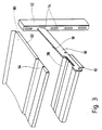
- the pendulum side plates 10,10 'described below are intended for filing shelves, which can be inserted from at least two spaced tubes 12 and a larger number of spaced apart into the elongated holes 14 of a hole grid arranged in the standpipes and cantilevered Plug carriers 16 exist.
- the plug-in supports 16 are composed of two flat material rods 16 ', 16' which are welded to one another at a distance, leaving a gap 18 at welding points 20, made of metal. In their rear area, inserted into the elongated hole 14 of the standpipe 12, the flat material rods are bent so that they lie flat against one another.
- the standpipes 12 can be fitted with plug-in supports 16 on both sides in the same elongated hole 14.
- plug-in carrier 16 In the upper edge of the plug-in carrier 16 there is an upwardly open recess 22 in the front region, which coincides with the open edge recess 24 in the side plates 10, 10 ', and in the region of which the side plates 10, 10' are suspended from above.
- the side plates 10,10 have two punched out of the plate material and one side projecting beyond the plate level locking tongues 30.32, the locking recesses 34.36 on their opposite sides facing end edges for receiving on the pendulum rods 38 arranged beads 40,42 are determined. Since the two locking tongues 30, 32 are designed differently, different side plates 10, 10 'are required for the right and left stop.
- the side plate 10, 10 At its upper edge, the side plate 10, 10 'has a double bent hook tongue 44 and two simple bends 46 and 48 arranged laterally next to the hook tongue 44. Both the hook tongue 44 and the two turns 46 and 48 point to the side opposite the locking tongues 30, 32. Furthermore, on the lower edge of the lateral flap 50 there is a bend 52 projecting rearward beyond the plate plane. A flap 56 is punched out on the opposite side and is only connected to the side plate 10 via a narrow, flexible material bridge 58. In the area of the upper edge 60 of the tab 56 there is a limit stop 62 which is stamped out on the side of the latching tongues 30, 32 from the plane of the plate and points upward in the manner of a hook.
- the pendulum side plate is initially slanted onto the adjacent flat material rod 16 'or 16' of the plug-in support 16 so that the hook tongue 44 engages behind the upper edge of the flat material rod in the area of the edge-open recess 22 and the bend 52 engages under the lower edge of the flat material rod .
- the bends 46, 48 strike against the upper edge in the region of the recess 22 open at the edge and the bend 52 against the lower edge of the flat material bar.
- the tab 56 is now bent by hand in the direction of the flat material rod until the limit stop 62 abuts against the side surface of the flat material rod and the upper edge 60 engages under the lower edge of the flat material rod.
- the material bridge 58 is plastically deformed. If an inclined surface (not shown) projecting to the side of the latching tongue 30, 32 is provided on the tab 56, on which the pendulum rod 38 can run open when it is snapped on, it is even possible to effect the locking automatically when the pendulum rod 38 is latched on.
- Bores 64 are provided in the lateral tabs 50 and 54, which, when plugged in, align with corresponding bores 66 of the plug carrier 16. In this way, it is possible to additionally screw the side plates 10, 10 'onto the plug-in supports and, for example, to combine them in add-on shelves with side plates of the old type, which were only screwable.
- a tray 90 can be plugged onto the plug carrier 16 from above, which can be inserted with its downward-pointing bends 92 into the gap 18 between the flat material rods 16 ', 16'.
- the tray 90 additionally has a longitudinal channel 94, which at its front edge in the open-edge recesses 22, 24 of the plug-in support 16 and the side plate 10,10 'engages positively.
Landscapes
- Connection Of Plates (AREA)
- Assembled Shelves (AREA)
- Clamps And Clips (AREA)
- Vehicle Step Arrangements And Article Storage (AREA)
- Tables And Desks Characterized By Structural Shape (AREA)
Priority Applications (1)
| Application Number | Priority Date | Filing Date | Title |
|---|---|---|---|
| AT89113322T ATE87444T1 (de) | 1988-09-02 | 1989-07-20 | Seitenplatte zur befestigung an einem stecktraeger fuer pendelregale. |
Applications Claiming Priority (2)
| Application Number | Priority Date | Filing Date | Title |
|---|---|---|---|
| DE3829882A DE3829882A1 (de) | 1988-09-02 | 1988-09-02 | Seitenplatte zur befestigung an einem stecktraeger fuer pendelregale |
| DE3829882 | 1988-09-02 |
Publications (2)
| Publication Number | Publication Date |
|---|---|
| EP0357920A1 EP0357920A1 (de) | 1990-03-14 |
| EP0357920B1 true EP0357920B1 (de) | 1993-03-31 |
Family
ID=6362178
Family Applications (1)
| Application Number | Title | Priority Date | Filing Date |
|---|---|---|---|
| EP89113322A Expired - Lifetime EP0357920B1 (de) | 1988-09-02 | 1989-07-20 | Seitenplatte zur Befestigung an einem Steckträger für Pendelregale |
Country Status (3)
| Country | Link |
|---|---|
| EP (1) | EP0357920B1 (https=) |
| AT (1) | ATE87444T1 (https=) |
| DE (2) | DE3829882A1 (https=) |
Cited By (1)
| Publication number | Priority date | Publication date | Assignee | Title |
|---|---|---|---|---|
| WO2004018117A1 (en) * | 2002-08-21 | 2004-03-04 | New Zealand Post Limited | A stand for mail sorting and other applications |
Family Cites Families (3)
| Publication number | Priority date | Publication date | Assignee | Title |
|---|---|---|---|---|
| GB965360A (en) * | 1962-04-26 | 1964-07-29 | Sankey Sheldon Ltd | Improvements in suspension means for use in suspended-filing systems |
| US3565381A (en) * | 1968-10-21 | 1971-02-23 | Earl J Oliver | Bracket structure |
| US4101108A (en) * | 1977-06-06 | 1978-07-18 | Lear Siegler, Inc. | Shelf clip |
-
1988
- 1988-09-02 DE DE3829882A patent/DE3829882A1/de active Granted
-
1989
- 1989-07-20 EP EP89113322A patent/EP0357920B1/de not_active Expired - Lifetime
- 1989-07-20 AT AT89113322T patent/ATE87444T1/de not_active IP Right Cessation
- 1989-07-20 DE DE8989113322T patent/DE58903939D1/de not_active Expired - Fee Related
Cited By (1)
| Publication number | Priority date | Publication date | Assignee | Title |
|---|---|---|---|---|
| WO2004018117A1 (en) * | 2002-08-21 | 2004-03-04 | New Zealand Post Limited | A stand for mail sorting and other applications |
Also Published As
| Publication number | Publication date |
|---|---|
| DE58903939D1 (de) | 1993-05-06 |
| ATE87444T1 (de) | 1993-04-15 |
| EP0357920A1 (de) | 1990-03-14 |
| DE3829882A1 (de) | 1990-03-15 |
| DE3829882C2 (https=) | 1990-07-19 |
Similar Documents
| Publication | Publication Date | Title |
|---|---|---|
| DE2850093C2 (de) | Halterungsanordnung für Schaltungsplatten | |
| EP3498128B1 (de) | System aus warenauflage und teilern | |
| DE102015105482B4 (de) | Schaltschrank oder Rack zur Aufnahme elektrischer Energiespeicher, insbesondere Batterien, und eine entsprechende Schaltschrank- oder Rackanordnung | |
| EP0315798A1 (de) | Etagenschirmblech für einen Baugruppenträger | |
| EP1522107B1 (de) | Vorrichtung zur befestigung eines gehäuses, insbesondere das einer kraftfahrzeug-batterie, an einer trägerplatte | |
| DE3925302C2 (https=) | ||
| DE3325681A1 (de) | Elektrische apparatedosenbaugruppe und dafuer vorgesehener befestigungswinkel | |
| EP0447942B1 (de) | Kontaktleiste für eine störstrahlungsdichte Verbindung benachbarter metallischer Wandelemente | |
| EP0283973B1 (de) | Vorrichtung zur Befestigung von Gehäusen in Öffnungen einer Schalttafel oder einer Rastersystemwand | |
| DE2846825B2 (de) | Wandzentrale | |
| EP1072179B1 (de) | Baugruppenträger | |
| EP0357920B1 (de) | Seitenplatte zur Befestigung an einem Steckträger für Pendelregale | |
| DE3634462C2 (https=) | ||
| EP0732788A1 (de) | Anordnung mit einer Deckenstütze und einer Konsole | |
| DE2552650C2 (https=) | ||
| DE102021130425A1 (de) | Befestigungsvorrichtung | |
| DE102020126866A1 (de) | Konsole für Fassadenelemente | |
| EP1145666B1 (de) | Regal, insbesondere für Bibliotheken | |
| EP2011668B1 (de) | Kennzeichenreiter | |
| DE2125431C3 (de) | An einem Hakenträgerprofil befestigbarer Garderobenhaken | |
| DE7334075U (de) | Montageplatte zur Befestigung von Bauteilen elektrischer Schaltungen für die Verwendung in elektrischen Schaltschränken u.dgl | |
| DE3112620C2 (de) | Rahmen für einschiebbare elektrische Baugruppen | |
| CH659119A5 (de) | Signalleuchtengehaeuse. | |
| DE9200731U1 (de) | Vorrichtung zur Herstellung von abgehängten Decken | |
| DE102020126860A1 (de) | Konsole für Fassadenelemente und Verfahren zu dessen Herstellung |
Legal Events
| Date | Code | Title | Description |
|---|---|---|---|
| PUAI | Public reference made under article 153(3) epc to a published international application that has entered the european phase |
Free format text: ORIGINAL CODE: 0009012 |
|
| AK | Designated contracting states |
Kind code of ref document: A1 Designated state(s): AT DE GB LU NL |
|
| 17P | Request for examination filed |
Effective date: 19900405 |
|
| 17Q | First examination report despatched |
Effective date: 19920430 |
|
| GRAA | (expected) grant |
Free format text: ORIGINAL CODE: 0009210 |
|
| AK | Designated contracting states |
Kind code of ref document: B1 Designated state(s): AT DE GB LU NL |
|
| REF | Corresponds to: |
Ref document number: 87444 Country of ref document: AT Date of ref document: 19930415 Kind code of ref document: T |
|
| REF | Corresponds to: |
Ref document number: 58903939 Country of ref document: DE Date of ref document: 19930506 |
|
| RAP2 | Party data changed (patent owner data changed or rights of a patent transferred) |
Owner name: LOUIS LEITZ KG |
|
| GBT | Gb: translation of ep patent filed (gb section 77(6)(a)/1977) |
Effective date: 19930426 |
|
| PGFP | Annual fee paid to national office [announced via postgrant information from national office to epo] |
Ref country code: AT Payment date: 19930713 Year of fee payment: 5 |
|
| PGFP | Annual fee paid to national office [announced via postgrant information from national office to epo] |
Ref country code: GB Payment date: 19930715 Year of fee payment: 5 |
|
| NLT2 | Nl: modifications (of names), taken from the european patent patent bulletin |
Owner name: LOUIS LEITZ KG TE STUTTGART, BONDSREPUBLIEK DUITSL |
|
| PGFP | Annual fee paid to national office [announced via postgrant information from national office to epo] |
Ref country code: NL Payment date: 19930731 Year of fee payment: 5 |
|
| PGFP | Annual fee paid to national office [announced via postgrant information from national office to epo] |
Ref country code: LU Payment date: 19930804 Year of fee payment: 5 |
|
| EPTA | Lu: last paid annual fee | ||
| PLBE | No opposition filed within time limit |
Free format text: ORIGINAL CODE: 0009261 |
|
| STAA | Information on the status of an ep patent application or granted ep patent |
Free format text: STATUS: NO OPPOSITION FILED WITHIN TIME LIMIT |
|
| 26N | No opposition filed | ||
| PG25 | Lapsed in a contracting state [announced via postgrant information from national office to epo] |
Ref country code: LU Free format text: LAPSE BECAUSE OF NON-PAYMENT OF DUE FEES Effective date: 19940720 Ref country code: GB Effective date: 19940720 Ref country code: AT Effective date: 19940720 |
|
| PG25 | Lapsed in a contracting state [announced via postgrant information from national office to epo] |
Ref country code: NL Effective date: 19950201 |
|
| NLV4 | Nl: lapsed or anulled due to non-payment of the annual fee | ||
| GBPC | Gb: european patent ceased through non-payment of renewal fee |
Effective date: 19940720 |
|
| PGFP | Annual fee paid to national office [announced via postgrant information from national office to epo] |
Ref country code: DE Payment date: 20000721 Year of fee payment: 12 |
|
| PG25 | Lapsed in a contracting state [announced via postgrant information from national office to epo] |
Ref country code: DE Free format text: LAPSE BECAUSE OF NON-PAYMENT OF DUE FEES Effective date: 20020501 |