EP0357920B1 - Small side-plate to be fixed on a bracket used with suspended filing racks - Google Patents
Small side-plate to be fixed on a bracket used with suspended filing racks Download PDFInfo
- Publication number
- EP0357920B1 EP0357920B1 EP89113322A EP89113322A EP0357920B1 EP 0357920 B1 EP0357920 B1 EP 0357920B1 EP 89113322 A EP89113322 A EP 89113322A EP 89113322 A EP89113322 A EP 89113322A EP 0357920 B1 EP0357920 B1 EP 0357920B1
- Authority
- EP
- European Patent Office
- Prior art keywords
- plate
- flat material
- edge
- plate according
- ledge
- Prior art date
- Legal status (The legal status is an assumption and is not a legal conclusion. Google has not performed a legal analysis and makes no representation as to the accuracy of the status listed.)
- Expired - Lifetime
Links
Images


Classifications
-
- A—HUMAN NECESSITIES
- A47—FURNITURE; DOMESTIC ARTICLES OR APPLIANCES; COFFEE MILLS; SPICE MILLS; SUCTION CLEANERS IN GENERAL
- A47B—TABLES; DESKS; OFFICE FURNITURE; CABINETS; DRAWERS; GENERAL DETAILS OF FURNITURE
- A47B96/00—Details of cabinets, racks or shelf units not covered by a single one of groups A47B43/00 - A47B95/00; General details of furniture
- A47B96/06—Brackets or similar supporting means for cabinets, racks or shelves
- A47B96/061—Cantilever brackets
-
- B—PERFORMING OPERATIONS; TRANSPORTING
- B42—BOOKBINDING; ALBUMS; FILES; SPECIAL PRINTED MATTER
- B42F—SHEETS TEMPORARILY ATTACHED TOGETHER; FILING APPLIANCES; FILE CARDS; INDEXING
- B42F15/00—Suspended filing appliances
- B42F15/007—Support structures for suspended files
- B42F15/0082—Support structures for suspended files with a fixed support
Definitions
- the invention relates to a side plate for attachment to a broad side surface of a plug carrier consisting of at least one flat material rod, preferably made of metal, for pendulum shelves or counters with at least one latching element for a pendulum rod protruding beyond the plate plane on the side opposite the flat material rod.
- the so-called pendulum side plates form special fittings for the plug-in supports, which can be used as multi-purpose supports for differently designed filing shelves.
- the plug-in supports that can be inserted into the locking holes of standpipes on a shelf at the desired compartment height can also be used to hold trays for letter folders and collectors, as well as with rods or cables for hanging files.
- a support structure for wire mesh shelves (US-A-3 565 381) to provide a side plate for attachment to a broad side surface of a plug carrier consisting of a flat material rod made of metal, which has at least one on the side opposite the flat material rod above the plane of the plate protruding locking element for a shelf element and a hook-shaped bend protruding beyond the plate level and engaging behind the flat material rod in the area of the upper narrow side edge.
- the invention is therefore based on the object to improve the known side plate of the type specified in such a way that the plug-in connection can be connected to the plug-in carrier with an easy-to-use and reliable connector despite the high loads.
- the tab is connected in one piece to the side plate via a flexible material bridge which is preferably arranged at a distance from the top edge of the tab and is oriented in the plane of the plate.
- the tab can be bent out of the plate level either by hand or automatically when the pendulum rod snaps on. In the latter case, an inclined surface protruding to the side of the latching elements is provided on the tab, on which the pendulum rod runs when it snaps on and thereby brings the tab into its locking position.
- the second shoulder which is arranged at a lateral distance from the tab that can be bent out of the plate plane, can be designed either as a single bend or as a hook-shaped bend engaging behind the flat material bar in the region of the lower narrow side edge.
- a limiting stop protruding on the side of the latching elements above the plate plane and above the upper edge of the tab, which abuts the broad side surface of the flat material rod when the tab is bent out, is formed.
- At least one of the upper narrow side edge of the flat material rod can additionally be on the side next to the upper hook-shaped bend comprehensive simple turn can be provided.
- the upper bends engage in an open-edge recess arranged in the course of the upper edge of the flat material rod.
- the upper bends can be bent out of the plane of the plate to form an opening which is essentially identical in width and depth to the open edge of the flat material bar.
- the side plates according to the invention are preferably fastened to plug-in supports which consist of two flat material rods which are connected to one another at a distance while leaving a gap. Only then is it possible to set up add-on shelves using simple means.
- the hook-shaped bends on the side panels grip expediently with their free ends in the gap area between the two flat material bars.
- the upper hook-shaped bends are advantageously arranged eccentrically within the open-edge recess, so that they do not collide with one another when they are plugged onto the adjacent flat material rods of a plug-in carrier.
- the pendulum side plates 10,10 'described below are intended for filing shelves, which can be inserted from at least two spaced tubes 12 and a larger number of spaced apart into the elongated holes 14 of a hole grid arranged in the standpipes and cantilevered Plug carriers 16 exist.
- the plug-in supports 16 are composed of two flat material rods 16 ', 16' which are welded to one another at a distance, leaving a gap 18 at welding points 20, made of metal. In their rear area, inserted into the elongated hole 14 of the standpipe 12, the flat material rods are bent so that they lie flat against one another.
- the standpipes 12 can be fitted with plug-in supports 16 on both sides in the same elongated hole 14.
- plug-in carrier 16 In the upper edge of the plug-in carrier 16 there is an upwardly open recess 22 in the front region, which coincides with the open edge recess 24 in the side plates 10, 10 ', and in the region of which the side plates 10, 10' are suspended from above.
- the side plates 10,10 have two punched out of the plate material and one side projecting beyond the plate level locking tongues 30.32, the locking recesses 34.36 on their opposite sides facing end edges for receiving on the pendulum rods 38 arranged beads 40,42 are determined. Since the two locking tongues 30, 32 are designed differently, different side plates 10, 10 'are required for the right and left stop.
- the side plate 10, 10 At its upper edge, the side plate 10, 10 'has a double bent hook tongue 44 and two simple bends 46 and 48 arranged laterally next to the hook tongue 44. Both the hook tongue 44 and the two turns 46 and 48 point to the side opposite the locking tongues 30, 32. Furthermore, on the lower edge of the lateral flap 50 there is a bend 52 projecting rearward beyond the plate plane. A flap 56 is punched out on the opposite side and is only connected to the side plate 10 via a narrow, flexible material bridge 58. In the area of the upper edge 60 of the tab 56 there is a limit stop 62 which is stamped out on the side of the latching tongues 30, 32 from the plane of the plate and points upward in the manner of a hook.
- the pendulum side plate is initially slanted onto the adjacent flat material rod 16 'or 16' of the plug-in support 16 so that the hook tongue 44 engages behind the upper edge of the flat material rod in the area of the edge-open recess 22 and the bend 52 engages under the lower edge of the flat material rod .
- the bends 46, 48 strike against the upper edge in the region of the recess 22 open at the edge and the bend 52 against the lower edge of the flat material bar.
- the tab 56 is now bent by hand in the direction of the flat material rod until the limit stop 62 abuts against the side surface of the flat material rod and the upper edge 60 engages under the lower edge of the flat material rod.
- the material bridge 58 is plastically deformed. If an inclined surface (not shown) projecting to the side of the latching tongue 30, 32 is provided on the tab 56, on which the pendulum rod 38 can run open when it is snapped on, it is even possible to effect the locking automatically when the pendulum rod 38 is latched on.
- Bores 64 are provided in the lateral tabs 50 and 54, which, when plugged in, align with corresponding bores 66 of the plug carrier 16. In this way, it is possible to additionally screw the side plates 10, 10 'onto the plug-in supports and, for example, to combine them in add-on shelves with side plates of the old type, which were only screwable.
- a tray 90 can be plugged onto the plug carrier 16 from above, which can be inserted with its downward-pointing bends 92 into the gap 18 between the flat material rods 16 ', 16'.
- the tray 90 additionally has a longitudinal channel 94, which at its front edge in the open-edge recesses 22, 24 of the plug-in support 16 and the side plate 10,10 'engages positively.
Landscapes
- Connection Of Plates (AREA)
- Assembled Shelves (AREA)
- Tables And Desks Characterized By Structural Shape (AREA)
- Clamps And Clips (AREA)
- Vehicle Step Arrangements And Article Storage (AREA)
Abstract
Description
Die Erfindung betrifft eine Seitenplatte zur Befestigung an einer Breitseitenfläche eines aus mindestens einer Flachmaterialstange vorzugsweise aus Metall bestehenden Steckträgers für Pendelregale oder -theken mit mindestens einem auf der der Flachmaterialstange gegenüberliegenden Seite über die Plattenebene überstehenden Rastorgan für eine Pendelstange.The invention relates to a side plate for attachment to a broad side surface of a plug carrier consisting of at least one flat material rod, preferably made of metal, for pendulum shelves or counters with at least one latching element for a pendulum rod protruding beyond the plate plane on the side opposite the flat material rod.
Die sogenannten Pendel-Seitenplatten bilden Spezialbeschläge für die Steckträger, die als Mehrzweckträger für unterschiedlich ausgestaltete Registraturregale verwendbar sind. So können die in Rastöffnungen von Standrohren eines Regals im Abstand der gewünschten Fachhöhe einsteckbaren Steckträger neben den Pendelstangen auch zur Aufnahme von Tablaren für Briefordner und -sammler sowie mit Stangen oder Zügen für Hängeregistraturen ausgestattet werden.The so-called pendulum side plates form special fittings for the plug-in supports, which can be used as multi-purpose supports for differently designed filing shelves. For example, in addition to the pendulum rods, the plug-in supports that can be inserted into the locking holes of standpipes on a shelf at the desired compartment height can also be used to hold trays for letter folders and collectors, as well as with rods or cables for hanging files.
Es sind Seitenplatten der eingangs angegebenen Art bekannt, die mittels zweier Gewindeschrauben mit Muttern an den Steckträgern anschraubbar sind. Bei der Montage eines Grundregals mit 7 Fächern müssen also 14 Seitenplatten mit 28 Schrauben an den dazugehörigen Steckträgern befestigt werden. Bei dem im übrigen ausschließlich durch Steckverbindungen aufbaubaren Regal erfordert dieser Schraubvorgang bei weitem den größten Arbeitsaufwand.Side plates of the type specified at the outset are known which can be screwed onto the plug-in supports by means of two threaded screws with nuts. When installing a basic shelf with 7 compartments, 14 side panels must be attached to the associated plug-in supports using 28 screws. In the case of the shelf, which can only be built up by plug-in connections, this screwing process requires the greatest amount of work by far.
Weiter ist es bei einer Tragstruktur für Drahtgitterregale an sich bekannt (US-A-3 565 381), eine Seitenplatte zur Befestigung an einer Breitseitenfläche eines aus einer Flachmaterialstange aus Metall bestehenden Steckträgers vorzusehen, die mindestens ein auf der der Flachmaterialstange gegenüberliegenden Seite über die Plattenebene überstehendes Rastorgan für ein Regalelement sowie eine über die Plattenebene überstehende, die Flachmaterialstange im Bereich der oberen Schmalseitenkante hintergreifende hakenförmige Abbiegung aufweist.Furthermore, it is known per se in a support structure for wire mesh shelves (US-A-3 565 381) to provide a side plate for attachment to a broad side surface of a plug carrier consisting of a flat material rod made of metal, which has at least one on the side opposite the flat material rod above the plane of the plate protruding locking element for a shelf element and a hook-shaped bend protruding beyond the plate level and engaging behind the flat material rod in the area of the upper narrow side edge.
Der Erfindung liegt daher die Aufgabe zugrunde, die bekannte Seitenplatte der eingangs angegebenen Art dahingehend zu verbessern, daß die mit einer einfach handhabbaren und trotz der hohen Belastungen zuverlässigen Steckverbindung mit dem Steckträger verbindbar ist.The invention is therefore based on the object to improve the known side plate of the type specified in such a way that the plug-in connection can be connected to the plug-in carrier with an easy-to-use and reliable connector despite the high loads.
Zur Lösung dieser Aufgabe wird gemäß der Erfindung die im Kennzeichenteil des Anspruchs 1 angegebenene Merkmalskombination vorgeschlagen. Weitere vorteilhafte Ausgestaltungen und Weiterbildungen der Erfindung ergeben sich aus den Unteransprüchen.To achieve this object, the combination of features specified in the characterizing part of claim 1 is proposed according to the invention. Further advantageous refinements and developments of the invention result from the subclaims.
Bei der erfindungsgemäßen Lösung wurde die Erkenntnis berücksichtigt, daß an den Seitenplatten einer Pendelregistratur beim Einrasten der Pendelstangen und beim Auf- Und Abhängen von Pendelmappen nicht nur nach unten weisende Schwerkräfte, sondern auch nach oben gerichtete Kräfte und Drehmomente angreifen, die eine entsprechende Verriegelung der Seitenplatte am Steckträger erfordern. Dementsprechend wird gemäß der Erfindung vorgeschlagen, daß mindestens eine über die Plattenebene überstehende, die Flachmaterialstange des Steckträgers im Bereich der oberen Schmalseitenkante übergreifende hakenförmige Abbiegung vorgesehen ist und daß zusätzlich zwei in seitlichem Abstand voneinander angeordnete, die untere Schmalseitenkante der Flachmaterialstange untergreifende Schultern vorgesehen sind, wobei eine der Schultern durch die Oberkante einer aus der Plattenebene herausbiegbaren Lasche gebildet ist.In the solution according to the invention, the knowledge was taken into account that on the side plates of a pendulum registry when the pendulum rods snap in and when hanging and hanging pendulum folders, not only do downward gravitational forces but also upward forces and torques attack, which lock the side plate accordingly on the plug carrier. Accordingly, it is proposed according to the invention that at least one hook-shaped bend projecting beyond the plate level and overlapping the flat material rod of the plug-in carrier in the region of the upper narrow side edge is provided, and that two shoulders are provided which are arranged at a lateral distance from one another and under the lower narrow side edge of the flat material rod, whereby one of the shoulders is formed by the upper edge of a tab that can be bent out of the plane of the plate.
Gemäß einer bevorzugten Ausgestaltung der Erfindung ist die Lasche über eine vorzugsweise im Abstand von der Laschenoberkante angeordnete, in der Plattenebene ausgerichtete biegsame Materialbrücke einstückig mit der Seitenplatte verbunden. Die Lasche kann dabei entweder von Hand oder selbsttätig beim Aufrasten der Pendelstange aus der Plattenebene herausgebogen werden. Im letzteren Fall ist an der Lasche eine zur Seite der Rastorgane überstehende Schrägfläche vorgesehen, auf der die Pendelstange beim Aufrasten aufläuft und dabei die Lasche in ihre Verriegelungsstellung bringt.According to a preferred embodiment of the invention, the tab is connected in one piece to the side plate via a flexible material bridge which is preferably arranged at a distance from the top edge of the tab and is oriented in the plane of the plate. The tab can be bent out of the plate level either by hand or automatically when the pendulum rod snaps on. In the latter case, an inclined surface protruding to the side of the latching elements is provided on the tab, on which the pendulum rod runs when it snaps on and thereby brings the tab into its locking position.
Die zweite, in seitlichem Abstand von der aus der Plattenebene herausbiegbaren Lasche angeordnete Schulter kann entweder als Einfachabbiegung oder als die Flachmaterialstange im Bereich der unteren Schmalseitenkante hintergreifende hakenförmige Abbiegung ausgebildet sein.The second shoulder, which is arranged at a lateral distance from the tab that can be bent out of the plate plane, can be designed either as a single bend or as a hook-shaped bend engaging behind the flat material bar in the region of the lower narrow side edge.
Gemäß einer weiteren vorteilhaften Ausgestaltung der Erfindung ist im Bereich der Laschenoberkante ein auf der Seite der Rastorgane über die Plattenebene und über die Laschenoberkante überstehender, beim Herausbiegen der Lasche gegen die Breitseitenfläche der Flachmaterialstange anschlagender Begrenzungsanschlag angeformt.According to a further advantageous embodiment of the invention, in the region of the upper edge of the tab, a limiting stop protruding on the side of the latching elements above the plate plane and above the upper edge of the tab, which abuts the broad side surface of the flat material rod when the tab is bent out, is formed.
Um eine zuverlässige Abstützung im Bereich der oberen Schmalseitenkante zu gewährleisten, kann seitlich neben der oberen hakenförmigen Abbiegung zusätzlich mindestens eine die obere Schmalseitenkante der Flachmaterialstange übergreifende einfache Abbiegung vorgesehen werden. Um auch in Längsrichtung des Steckträgers einen Formschluß zu erzielen, greifen die oberen Abbiegungen in eine im Verlauf der Oberkante der Flachmaterialstange angeordnete randoffene Aussparung ein. Die oberen Abbiegungen können dabei unter Bildung einer sich mit der randoffenen Aussparung der Flachmaterialstange in ihrer Breite und Tiefe im wesentlichen deckenden randoffenen Aussparung aus der Plattenebene herausgebogen werden. Dadurch ist es bei auf den Steckträger aufgesteckter Seitenplatte möglich, auch solche Tablare auf die Seitenplatten aufzulegen, die mit in die randoffenen Aussparungen eingreifenden Sicken oder Vertiefungen versehen sind.In order to ensure reliable support in the area of the upper narrow side edge, at least one of the upper narrow side edge of the flat material rod can additionally be on the side next to the upper hook-shaped bend comprehensive simple turn can be provided. In order to achieve a positive connection in the longitudinal direction of the plug-in support as well, the upper bends engage in an open-edge recess arranged in the course of the upper edge of the flat material rod. The upper bends can be bent out of the plane of the plate to form an opening which is essentially identical in width and depth to the open edge of the flat material bar. As a result, when the side plate is attached to the plug-in carrier, it is also possible to place on the side plates such trays which are provided with beads or depressions which engage in the open-edge recesses.
Weiter ist es zweckmäßig, im Bereich von flach gegen die Breitseitenfläche der Flachmaterialstange anliegenden Plattenteilen Bohrungen vorzusehen, die im aufgesteckten Zustand der Seitenplatte mit Bohrungen im Steckträger fluchten. Dadurch können die Seitenplatten zusätzlich an den Steckträgern angeschraubt und mit den anschraubbaren Seitenplatten alter Bauart kombiniert werden.Furthermore, it is expedient to provide bores in the region of plate parts lying flat against the broad side surface of the flat material rod, which bores are aligned with bores in the plug-in carrier when the side plate is plugged on. This means that the side panels can also be screwed onto the plug-in supports and combined with the screw-on side panels of the old design.
Die erfindungsgemäßen Seitenplatten werden bevorzugt an solchen Steckträgern befestigt, die aus zwei im Abstand unter Freilassung eines Spalts miteinander verbundenen Flachmaterialstangen bestehen. Erst damit ist es möglich, mit einfachen Mitteln Anbauregale aufzubauen. Die hakenförmigen Abbiegungen der Seitenplatten greifen hierbei mit ihren freien Enden zweckmäßig in den Spaltbereich zwischen den beiden Flachmaterialstangen ein. Um problemlos Anbauregale mit den steckbaren Seitenplatten ausstatten zu können, sind die oberen hakenförmigen Abbiegungen vorteilhafterweise außermittig innerhalb der randoffenen Aussparung angeordnet, so daß sie beim Aufstecken auf die einander benachbarten Flachmaterialstangen eines Steckträgers nicht miteinander kollidieren.The side plates according to the invention are preferably fastened to plug-in supports which consist of two flat material rods which are connected to one another at a distance while leaving a gap. Only then is it possible to set up add-on shelves using simple means. The hook-shaped bends on the side panels grip expediently with their free ends in the gap area between the two flat material bars. In order to be able to easily equip add-on shelves with the pluggable side plates, the upper hook-shaped bends are advantageously arranged eccentrically within the open-edge recess, so that they do not collide with one another when they are plugged onto the adjacent flat material rods of a plug-in carrier.
Im folgenden wird die Erfindung anhand eines in der Zeichnung in schematischer Weise dargestellten Ausführungsbeispiels näher erläutert. Es zeigen
- Fig. 1
- einen Ausschnitt aus einem Standrohr eines Registraturregals mit Steckträger und zwei Pendel-Seitenplatten in schaubildlicher Explosionsdarstellung;
- Fig. 2
- eine Darstellung entsprechend Fig. 1 mit montierter Pendel-Seitenplatte und Pendelstange;
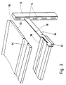
- Fig. 3
- eine Rückenansicht der montierten Pendel-Seitenplatte gemäß Fig. 2 mit Abdecktablar;
- Fig. 4
- eine Breitseitenansicht einer Pendelseitenplatte für die Rechtsmontage;
- Fig. 5
- eine Draufsicht auf die obere Schmalseite der Pendelseitenplatte nach Fig. 4.
- Fig. 1
- a section of a standpipe of a filing rack with plug-in support and two pendulum side plates in a diagrammatic exploded view;
- Fig. 2
- a representation corresponding to Figure 1 with mounted pendulum side plate and pendulum rod.
- Fig. 3
- a rear view of the mounted pendulum side plate according to FIG 2 with cover shelf.
- Fig. 4
- a broad side view of a pendulum side plate for right assembly;
- Fig. 5
- 4 shows a plan view of the upper narrow side of the pendulum side plate according to FIG. 4.
Die im folgenden beschriebenen Pendel-Seitenplatten 10,10′ sind für Registratur-Regale bestimmt, die aus mindestens zwei im Abstand voneinander angeordneten Standrohren 12 und einer größeren Anzahl von im Fachabstand voneinander in die Langlöcher 14 eines in den Standrohren angeordneten Lochrasters einsteckbaren und frei überkragenden Steckträgern 16 bestehen. Die Steckträger 16 sind aus zwei im Abstand unter Freilassung eines Spalts 18 an Schweißpunkten 20 miteinander verschweißten Flachmaterialstangen 16′,16˝ aus Metall zusammengesetzt. In ihrem rückwärtigen, in das Langloch 14 des Standrohrs 12 eingesetzten Bereich sind die Flachmaterialstangen so gebogen, daß sie flächig gegeneinander anliegen. Da sie mit ihrer gemeinsamen Wandstärke nur die Hälfte der Lochweite 14 einnehmen, ist es möglich, daß die Standrohre 12 im gleichen Langloch 14 beidseitig mit Steckträgern 16 bestückt werden können. In der Oberkante der Steckträger 16 befindet sich im vorderen Bereich eine nach oben randoffene Aussparung 22, die sich mit der randoffenen Aussparung 24 in den Seitenplatten 10,10′ deckt, und in deren Bereich die Seitenplatten 10,10′ von oben her eingehängt werden.The
Die Seitenplatten 10,10′ weisen zwei aus dem Plattenmaterial ausgestanzte und einseitig über die Plattenebene überstehende Rastzungen 30,32 auf, die an ihren nach einander entgegengesetzten Seiten weisenden Stirnkanten Rastaussparungen 34,36 zur Aufnahme von an den Pendelstangen 38 angeordneten Randwulsten 40,42 bestimmt sind. Da die beiden Rastzungen 30,32 unterschiedlich ausgebildet sind, werden verschiedene Seitenplatten 10,10′ für den Rechts- und Linksanschlag benötigt.The
An ihrer Oberkante weist die Seitenplatte 10,10′ eine doppelt abgebogene Hakenzunge 44 sowie zwei seitlich neben der Hakenzunge 44 angeordnete einfache Abbiegungen 46 und 48 auf. Sowohl die Hakenzunge 44 als auch die beiden Abbiegungen 46 und 48 weisen nach der den Rastzungen 30,32 gegenüberliegenden Seite. Weiter befindet sich an der Unterkante des seitlichen Lappens 50 eine nach hinten über die Plattenebene überstehende Abbiegung 52. Auf der gegenüberliegenden Seite ist eine Lasche 56 ausgestanzt, die nur über eine schmale, biegsame Materialbrücke 58 mit der Seitenplatte 10 verbunden ist. Im Bereich der Oberkante 60 der Lasche 56 befindet sich ein auf der Seite der Rastzungen 30,32 aus der Plattenebene herausgeprägter, hakenförmig nach oben weisender Begrenzungsanschlag 62.At its upper edge, the
Bei der Montage wird die Pendel-Seitenplatte zunächst schräg auf die benachbarte Flachmaterialstange 16′ bzw. 16˝ des Steckträgers 16 so aufgesteckt, daß die Hakenzunge 44 die Oberkante der Flachmaterialstange im Bereich der randoffenen Aussparung 22 hintergreift und die Abbiegung 52 die Unterkante der Flachmaterialstange untergreift. Beim anschließenden Kippen der Seitenplatte schlagen die Abbiegungen 46,48 gegen die Oberkante im Bereich der randoffenen Aussparung 22 und die Abbiegung 52 gegen die Unterkante der Flachmaterialstange an. Zur Lagesicherung wird nun noch die Lasche 56 von Hand in Richtung Flachmaterialstange gebogen, bis der Begrenzungsanschlag 62 gegen die Seitenfläche der Flachmaterialstange anschlägt und die Oberkante 60 die Unterkante der Flachmaterialstange untergreift. Bei dem Biegevorgang wird die Materialbrücke 58 plastisch verformt. Wenn an der Lasche 56 einer zu Seite der Rastzunge 30,32 überstehende, nicht dargestellte Schrägfläche vorgesehen wird, an der die Pendelstange 38 beim Aufrasten auflaufen kann, ist es sogar möglich, die Verriegelung selbsttätig beim Aufrasten der Pendelstange 38 zu bewerkstelligen.During assembly, the pendulum side plate is initially slanted onto the adjacent flat material rod 16 'or 16' of the plug-in
In den seitlichen Lappen 50 und 54 sind Bohrungen 64 vorgesehen, die in aufgestecktem Zustand mit entsprechenden Bohrungen 66 des Steckträgers 16 fluchten. Auf diese Weise ist es möglich, die Seitenplatten 10,10′ an den Steckträgern zusätzlich anzuschrauben und beispielsweise in Anbauregalen mit Seitenplatten alter Bauart, die ausschließlich schraubbar waren, zu kombinieren.
Wie aus Fig. 3 zu ersehen ist, kann auf die Steckträger 16 von oben her ein Tablar 90 aufgesteckt werden, das mit seinen nach unten weisenden Abkantungen 92 in den Spalt 18 zwischen den Flachmaterialstangen 16′,16˝ einführbar ist. Das Tablar 90 weist zusätzlich eine Längsrinne 94 auf, die an ihrem stirnseitigen Rand in die randoffenen Aussparungen 22,24 des Steckträgers 16 und der Seitenplatte 10,10′ formschlüssig eingreift.As can be seen from Fig. 3, a
Claims (13)
- Side-plate for attachment to a broadside surface of a plug-in type bracket, comprising at least one bar of a flat material (16', 16"), preferably metal, for suspended shelves or bars, and having at least one detent element (30, 32) for a suspended bar (38), which element extends beyond the plate plane on the side opposite the bar of flat material bar (16', 16") , and at least one hook-shaped bend (44), which protrudes over the plate plane which reaches behind the strip of flat material (16', 16") in the region of the upper narrow-side edge, characterised by two shoulders, which are arranged at a lateral distance from each other and reach under the lower narrow-side edge of the strip of flat material (16', 16"), wherein one of the shoulders is formed by the top edge of a ledge (56) which is bent out of the plate plane (56).
- Side-plate according to claim 1, characterised in that the ledge (56) is integrally connected to the side-plate (10, 10') via a flexible material link which is preferably arranged at a distance from the top edge of the ledge (60) and aligned in the plate plane.
- Side-plate according to claim 1 or 2, characterised in that a second shoulder is formed by single bend (52) which protrudes over the plate plane.
- Side-plate according to claim 1 or 2, characterised in that a second shoulder is formed by a hook-shaped bend, which protrudes over the plate plane and reaches behind the strip of flat material (16', 16") in the area of the bottom narrow-side edge.
- Side-plate according to one of claims 1 to 3, characterised in that a limiting stop (62) is formed in the area of the top edge of the ledge (60), which stop protrudes at the side of the detent elements (30, 32) over the plate plane and over the top edge of the ledge (60) and which abuts against the broadside surface of the strip of flat material (16', 16") when the ledge (56) is bent out.
- Side-plate according to one of claims 1 to 5, characterised in that at least one single bend (46, 48), which reaches over the top narrow-side edge of the strip of flat material (16', 16"), is arranged laterally along the upper hook-shaped bend (44).
- Side-plate according to one of claims 1 to 6, characterised in that the top bends (44, 46, 48) engage an open-edged cut-out arranged in the extension of the top edge of the strip of flat material.
- Side-plate according to claim 7, characterised in that the top bends (44, 46, 48) are bent out of the plate plane whilst forming an open-edged cut-out (24) which substantially corresponds in width and depth with the open-edged cut-out (22) of the bracket.
- Side-plate according to one of claims 1 to 8, characterised in that holes are arranged in the area of plate sections (50, 54) which abut flat against the broadside surfaces of the strip of flat material (16', 16"), which in their pushed-on state lie flush with holes (66) in the bracket (16).
- Side-plate according to one of claims 1 to 9, wherein the plug-in bracket (16) is formed by two strips of flat material (16', 16") which are interconnected at a distance whilst maintaining a gap (18), characterised in that the hook-shaped bend (44) engages with its free end a gap (18) between the two strips of flat material (16', 16").
- Side-plate according to one of claims 8 to 10, characterised in that the top hook-shaped bend (44) is eccentrically arranged within the open-edged cut-out (24).
- Side-plate according to one of claims 5 to 11, characterised in that the limiting stop (62) protrudes over the plate plane by less than the material thickness of the strip of flat material (16', 16").
- Side-plate according to one of claims 1 to 12, characterised by a slanted surface, which protrudes at the ledge (56) to the side of the detent elements (30, 32), onto which a suspended bar (38) is pushed whilst being detented onto a detent element (30, 32) whilst bending out a ledge (56).
Priority Applications (1)
| Application Number | Priority Date | Filing Date | Title |
|---|---|---|---|
| AT89113322T ATE87444T1 (en) | 1988-09-02 | 1989-07-20 | SIDE PLATE FOR MOUNTING TO A PLUG-IN BRACKET FOR SWINGING SHELVES. |
Applications Claiming Priority (2)
| Application Number | Priority Date | Filing Date | Title |
|---|---|---|---|
| DE3829882A DE3829882A1 (en) | 1988-09-02 | 1988-09-02 | SIDE PLATE FOR FASTENING ON A PLUG HOLDER FOR PENDULAR SHELVES |
| DE3829882 | 1988-09-02 |
Publications (2)
| Publication Number | Publication Date |
|---|---|
| EP0357920A1 EP0357920A1 (en) | 1990-03-14 |
| EP0357920B1 true EP0357920B1 (en) | 1993-03-31 |
Family
ID=6362178
Family Applications (1)
| Application Number | Title | Priority Date | Filing Date |
|---|---|---|---|
| EP89113322A Expired - Lifetime EP0357920B1 (en) | 1988-09-02 | 1989-07-20 | Small side-plate to be fixed on a bracket used with suspended filing racks |
Country Status (3)
| Country | Link |
|---|---|
| EP (1) | EP0357920B1 (en) |
| AT (1) | ATE87444T1 (en) |
| DE (2) | DE3829882A1 (en) |
Cited By (1)
| Publication number | Priority date | Publication date | Assignee | Title |
|---|---|---|---|---|
| WO2004018117A1 (en) * | 2002-08-21 | 2004-03-04 | New Zealand Post Limited | A stand for mail sorting and other applications |
Family Cites Families (3)
| Publication number | Priority date | Publication date | Assignee | Title |
|---|---|---|---|---|
| GB965360A (en) * | 1962-04-26 | 1964-07-29 | Sankey Sheldon Ltd | Improvements in suspension means for use in suspended-filing systems |
| US3565381A (en) * | 1968-10-21 | 1971-02-23 | Earl J Oliver | Bracket structure |
| US4101108A (en) * | 1977-06-06 | 1978-07-18 | Lear Siegler, Inc. | Shelf clip |
-
1988
- 1988-09-02 DE DE3829882A patent/DE3829882A1/en active Granted
-
1989
- 1989-07-20 DE DE8989113322T patent/DE58903939D1/en not_active Expired - Fee Related
- 1989-07-20 EP EP89113322A patent/EP0357920B1/en not_active Expired - Lifetime
- 1989-07-20 AT AT89113322T patent/ATE87444T1/en not_active IP Right Cessation
Cited By (1)
| Publication number | Priority date | Publication date | Assignee | Title |
|---|---|---|---|---|
| WO2004018117A1 (en) * | 2002-08-21 | 2004-03-04 | New Zealand Post Limited | A stand for mail sorting and other applications |
Also Published As
| Publication number | Publication date |
|---|---|
| EP0357920A1 (en) | 1990-03-14 |
| ATE87444T1 (en) | 1993-04-15 |
| DE58903939D1 (en) | 1993-05-06 |
| DE3829882A1 (en) | 1990-03-15 |
| DE3829882C2 (en) | 1990-07-19 |
Similar Documents
| Publication | Publication Date | Title |
|---|---|---|
| DE2850093C2 (en) | Mounting arrangement for circuit boards | |
| EP0315798B1 (en) | Intermediate shielded sheet member for an electronic rack | |
| EP3498128B1 (en) | System comprising goods support and dividers | |
| DE3705331A1 (en) | MOUNTING UNIT FOR PRINTED CIRCUIT | |
| DE102015105482B4 (en) | Control cabinet or rack for receiving electrical energy storage, especially batteries, and a corresponding cabinet or rack assembly | |
| EP1522107B1 (en) | Device for fixing a housing, especially a housing pertaining to a motor vehicle battery, to a carrier plate | |
| DE2718442C3 (en) | Assembly comprising a base plate provided with a printed circuit and a holding device for holding and adjusting several electronic components lying next to one another | |
| EP0283973B1 (en) | Device for mounting housings in the openings of a switchboard or a matrix panel | |
| EP0447942B1 (en) | EMI impermeable multiple plug for interconnection of metallic board elements | |
| DE2846825B2 (en) | Wall central | |
| DE3325681A1 (en) | ELECTRICAL APPARATUS PANEL ASSEMBLY AND PROVIDED FASTENING ANGLE | |
| EP0357920B1 (en) | Small side-plate to be fixed on a bracket used with suspended filing racks | |
| DE3634462C2 (en) | ||
| EP1072179B1 (en) | Subrack | |
| DE2552650C2 (en) | ||
| DE3740563C2 (en) | ||
| DE4141559C2 (en) | Guide holder for electronic assemblies | |
| DE7334075U (en) | Mounting plate for attaching components of electrical circuits for use in electrical cabinets and the like | |
| DE102020126866A1 (en) | Console for facade elements | |
| DE3112620C2 (en) | Frame for slide-in electrical assemblies | |
| CH659119A5 (en) | SIGNAL LIGHT HOUSING. | |
| DE102020126860A1 (en) | Bracket for facade elements and method for its manufacture | |
| DE102021130425A1 (en) | fastening device | |
| DE102019104723A1 (en) | Control cabinet arrangement with a control cabinet and at least one socket strip | |
| EP0753991A1 (en) | Subrack for cards |
Legal Events
| Date | Code | Title | Description |
|---|---|---|---|
| PUAI | Public reference made under article 153(3) epc to a published international application that has entered the european phase |
Free format text: ORIGINAL CODE: 0009012 |
|
| AK | Designated contracting states |
Kind code of ref document: A1 Designated state(s): AT DE GB LU NL |
|
| 17P | Request for examination filed |
Effective date: 19900405 |
|
| 17Q | First examination report despatched |
Effective date: 19920430 |
|
| GRAA | (expected) grant |
Free format text: ORIGINAL CODE: 0009210 |
|
| AK | Designated contracting states |
Kind code of ref document: B1 Designated state(s): AT DE GB LU NL |
|
| REF | Corresponds to: |
Ref document number: 87444 Country of ref document: AT Date of ref document: 19930415 Kind code of ref document: T |
|
| REF | Corresponds to: |
Ref document number: 58903939 Country of ref document: DE Date of ref document: 19930506 |
|
| RAP2 | Party data changed (patent owner data changed or rights of a patent transferred) |
Owner name: LOUIS LEITZ KG |
|
| GBT | Gb: translation of ep patent filed (gb section 77(6)(a)/1977) |
Effective date: 19930426 |
|
| PGFP | Annual fee paid to national office [announced via postgrant information from national office to epo] |
Ref country code: AT Payment date: 19930713 Year of fee payment: 5 |
|
| PGFP | Annual fee paid to national office [announced via postgrant information from national office to epo] |
Ref country code: GB Payment date: 19930715 Year of fee payment: 5 |
|
| NLT2 | Nl: modifications (of names), taken from the european patent patent bulletin |
Owner name: LOUIS LEITZ KG TE STUTTGART, BONDSREPUBLIEK DUITSL |
|
| PGFP | Annual fee paid to national office [announced via postgrant information from national office to epo] |
Ref country code: NL Payment date: 19930731 Year of fee payment: 5 |
|
| PGFP | Annual fee paid to national office [announced via postgrant information from national office to epo] |
Ref country code: LU Payment date: 19930804 Year of fee payment: 5 |
|
| EPTA | Lu: last paid annual fee | ||
| PLBE | No opposition filed within time limit |
Free format text: ORIGINAL CODE: 0009261 |
|
| STAA | Information on the status of an ep patent application or granted ep patent |
Free format text: STATUS: NO OPPOSITION FILED WITHIN TIME LIMIT |
|
| 26N | No opposition filed | ||
| PG25 | Lapsed in a contracting state [announced via postgrant information from national office to epo] |
Ref country code: LU Free format text: LAPSE BECAUSE OF NON-PAYMENT OF DUE FEES Effective date: 19940720 Ref country code: GB Effective date: 19940720 Ref country code: AT Effective date: 19940720 |
|
| PG25 | Lapsed in a contracting state [announced via postgrant information from national office to epo] |
Ref country code: NL Effective date: 19950201 |
|
| NLV4 | Nl: lapsed or anulled due to non-payment of the annual fee | ||
| GBPC | Gb: european patent ceased through non-payment of renewal fee |
Effective date: 19940720 |
|
| PGFP | Annual fee paid to national office [announced via postgrant information from national office to epo] |
Ref country code: DE Payment date: 20000721 Year of fee payment: 12 |
|
| PG25 | Lapsed in a contracting state [announced via postgrant information from national office to epo] |
Ref country code: DE Free format text: LAPSE BECAUSE OF NON-PAYMENT OF DUE FEES Effective date: 20020501 |