EP0357529B1 - Vorrichtung zum drucklosen Ausrichten von verschiedenen Gegenständen, insbesondere von Flaschen - Google Patents
Vorrichtung zum drucklosen Ausrichten von verschiedenen Gegenständen, insbesondere von Flaschen Download PDFInfo
- Publication number
- EP0357529B1 EP0357529B1 EP89440049A EP89440049A EP0357529B1 EP 0357529 B1 EP0357529 B1 EP 0357529B1 EP 89440049 A EP89440049 A EP 89440049A EP 89440049 A EP89440049 A EP 89440049A EP 0357529 B1 EP0357529 B1 EP 0357529B1
- Authority
- EP
- European Patent Office
- Prior art keywords
- conveyer
- bottles
- conveyor
- feed
- transition
- Prior art date
- Legal status (The legal status is an assumption and is not a legal conclusion. Google has not performed a legal analysis and makes no representation as to the accuracy of the status listed.)
- Expired - Lifetime
Links
Images
Classifications
-
- B—PERFORMING OPERATIONS; TRANSPORTING
- B65—CONVEYING; PACKING; STORING; HANDLING THIN OR FILAMENTARY MATERIAL
- B65G—TRANSPORT OR STORAGE DEVICES, e.g. CONVEYORS FOR LOADING OR TIPPING, SHOP CONVEYOR SYSTEMS OR PNEUMATIC TUBE CONVEYORS
- B65G47/00—Article or material-handling devices associated with conveyors; Methods employing such devices
- B65G47/52—Devices for transferring articles or materials between conveyors i.e. discharging or feeding devices
- B65G47/68—Devices for transferring articles or materials between conveyors i.e. discharging or feeding devices adapted to receive articles arriving in one layer from one conveyor lane and to transfer them in individual layers to more than one conveyor lane or to one broader conveyor lane, or vice versa, e.g. combining the flows of articles conveyed by more than one conveyor
- B65G47/682—Devices for transferring articles or materials between conveyors i.e. discharging or feeding devices adapted to receive articles arriving in one layer from one conveyor lane and to transfer them in individual layers to more than one conveyor lane or to one broader conveyor lane, or vice versa, e.g. combining the flows of articles conveyed by more than one conveyor from a single conveyor lane consisting of one conveyor or several adjacent conveyors
Definitions
- the invention relates to a pressureless aligner for various objects such as bottles comprising a multi-track feed conveyor, an intermediate conveyor formed by a plurality of juxtaposed pallet chains and surmounted by a curvilinear guide ramp and a single-channel exit conveyor.
- the invention relates, more particularly, to the industry specialized in the field of conveying various objects and, in particular, of bottles.
- aligners are arranged upstream of machines such as fillers, labeling machines, capping units or the like, in order to ensure the supply of the latter, in bottles arriving one behind the other.
- these pressureless aligners are formed by a multi-track feed conveyor on which the bottles arranged in bulk move at low speed.
- This feed conveyor leads to an intermediate conveyor composed of several elementary pallet chains arranged side by side and surmounted by a curvilinear guide ramp pushing transversely said bottles from one elementary pallet chain to the next.
- Each of the tracks of this intermediate conveyor has a different running speed, increasing in a direction transverse to the direction of advance of the bottles, so as to accelerate them gradually and reduce the width of the flow coming from the feed conveyor.
- a first solution reducing the aforementioned risks, consists in considerably extending the length of the intermediate conveyor so that the probability of a bottle appearing in double file at the entrance to the exit conveyor is approximately zero.
- Document FR-A-2,533,200 also discloses pressureless aligners with a design substantially identical to that described above and comprising a feed conveyor, an intermediate conveyor and a single-channel exit conveyor.
- the intermediate conveyor is inclined transversely with respect to the advance of the bottles, by an angle of approximately 5 ° to 8 °.
- the stream of bottles arriving by the supply conveyor opens into the lower part on the intermediate conveyor and progresses, under the effect of the advance of the pallet chains, along the guide ramp pushing them back into the part high leading to the single track exit conveyor.
- the influence of the transverse inclination facilitates, on the one hand, the alignment of the bottles and the evacuation of glass debris or of the coated bottles, possibly, disposed on this intermediate conveyor.
- the fact remains that the risks of double file bottles persist and that the length of this pressureless aligner is kept consistent.
- a pressureless aligner for containers, in particular bottles comprising a multi-way feed conveyor leading to an intermediate conveyor constituted by a juxtaposition of pallet chains. animated by a progressively increasing speed gradient, and a single-track exit conveyor.
- the intermediate conveyor is subdivided into two sections connected by means of a transition conveyor. More specifically, on the first section of the transporter intermediate, the guide ramp surmounting the juxtaposed pallet chains communicates to the containers a trajectory with a transverse component of direction opposite to the transverse component communicated by the guide ramp to the containers on the second section.
- the transition transporter connecting the two sections of the intermediate transporter can adopt a curved trajectory so that the second section is not necessarily located in the extension of the first section. It is pointed out that such a curved transition transporter can contribute to the alignment of the containers under the effect of the resulting centrifugal force. It should be noted that, on either side of this transition conveyor, comprising several tracks, are fitted guide rails constituting the extension of the guide ramp surmounting, as the case may be, the first section or the second section of the intermediate conveyor .
- the present invention aims to remedy all of the aforementioned drawbacks.
- the invention as characterized in the claims, solves the problem and consists of a pressureless aligner of various objects, such as bottles, comprising a multi-way feed conveyor, an intermediate conveyor formed of a plurality of elementary pallet chains juxtaposed and surmounted by a curvilinear guide ramp and a single-channel exit conveyor, said intermediate conveyor leading to a transition conveyor with a curved path and at least two tracks, this transition conveyor being disposed upstream of the outlet conveyor and surmounted by a curvilinear guide ramp resuming the guiding of the bottles on their opposite side with respect to the guiding being effected on the intermediate conveyor, this substantially in the middle and outside of the turn defined by the transition conveyor, at the downstream end of said intermediate conveyor.
- the pressureless aligner 1, according to the invention, and shown in the various figures, is intended for conveying various objects between two separate processing units, one of which is located upstream and the other downstream of the production line.
- these processing units operate according to different production rates requiring the formation of a buffer stock on the conveyor ensuring their connection. Usually, this consists of slowing down and distributing the objects leaving with a regular pitch from the processing machine located upstream, on a multi-channel conveyor. Finally, the stream of bottles thus formed must again be narrowed so as to feed the machine processing, located downstream, of objects arriving in a single queue.
- an object aligner is used whose size must be reduced to a minimum so as to reduce the size of the production installations.
- This characteristic is essential, in particular, in the context of transporting containers such as bottles.
- the glass constituting, generally, these bottles is put to the test and, moreover, is a noise generator which is particularly troublesome for the personnel.
- the present description refers to a pressureless aligner in the context of an application to the transport of bottles, however, it will also find its utility for conveying objects of different shapes, dimensions and nature.
- this pressureless aligner 1 comprises a feed conveyor 2 provided with a plurality of tracks 3, 4, 5, arranged side by side and driven at an identical feed speed.
- This feed conveyor 2 leads to an intermediate multi-track conveyor 6 serving to accelerate and shrink the stream of bottles 7 coming from said feed conveyor 2.
- the intermediate conveyor 6 is formed by several elementary pallet chains 8, 9 ... juxtaposed and animated, each one, with a different advance speed, increasing transversely relative to the direction of advance 10 of the bottles 11.
- This arrangement is particularly known to the skilled person and it will be easy for him to determine the gradient of the speeds as a function of the type of objects transported and in particular, the weight of the bottles and their size in general.
- the driving of these elementary paddle chains 8, 9 at differential speeds is done by means of drive means 12 and transmission 13 known per se.
- This intermediate conveyor 6 is surmounted by a guide ramp 14, of curvilinear shape, making it possible to gradually push back the bottles 11 arriving from the feed conveyor 3, from the tracks, driven at a slow speed, towards channels subject to faster scrolling. This results in a progressive acceleration of the bottles 11 and a narrowing of the flow 7 arriving at the inlet of the intermediate conveyor 6.
- the bottles 11 are practically aligned one behind the other, with from time to time, a bottle 15 held in double file. Alignment of the latter, carried out according to a process identical to that applied to the narrowing of the stream of bottles 7, would impose a significant additional extension of the intermediate conveyor 6, without, however, the result being guaranteed one hundred percent.
- this intermediate conveyor 6 leads to a transition conveyor with a curved trajectory 16 provided with means 17 for aligning these bottles 15 held in double file.
- These means 17 are constituted by a curvilinear guide ramp 18 surmounting the transition conveyor 16 and resuming the guiding of the bottles 11 and 15, substantially in the middle and outside of the turn 19 leading to the downstream end 20 of the intermediate conveyor 6
- this recovery by the ramp of guiding 18 of the bottles 11 and 15 takes place on their opposite side with respect to the guiding having taken place on said intermediate conveyor 6 by means of the ramp 14 surmounting the latter.
- the effect of this particular arrangement is to increase slightly, the friction forces applied to the bottles in double file 15 so as to push them between two aligned bottles 11 conveyed freely on the transition conveyor 16.
- the upstream end 27 of this guide ramp 18 is, substantially, curved towards the outside of the turn 19 so that the non-aligned bottles 15 do not abut against the edge 28 of said guide ramp 18.
- the advantage obtained thanks to this characteristic of the pressureless aligner 1, according to the invention, consists in that its total length 21 is substantially less than the pressureless aligners known up to now, while guaranteeing perfect alignment of the bottles. . This obviously results in a smaller footprint.
- the addition of a curved conveyor also offers the possibility of easily modulating the configuration of the aligner without pressure, so as to integrate it without great difficulty in any type of installation. This feature will be detailed further on in the description.
- this transition conveyor 16 is necessarily of the multi-channel type, comprising a number of elementary pallet chains 22, 23 between 2 and 4, it is necessary to ensure the orientation of the bottles in the direction of a conveyor single-track outlet 24 terminating at the downstream end 25 of said transition conveyor 16.
- the curvilinear guide ramp 18 surmounting the latter gives the bottles 11, at this downstream end 25, a trajectory with transverse component so to push the latter towards the outlet conveyor 24.
- the intermediate conveyor 6 can, optionally, be inclined in the direction of advance of the bottles 11 to ensure the evacuation of the lying bottles and glass debris at the outlet of said intermediate conveyor 6 and, more precisely, at the first turn 19 of the transition conveyor 16 terminating at its downstream end 20. It will be noted that the distance respected by the guide ramp 18 relative to the plane of the elementary pallet chains 22, 23 will be provided sufficient to allow the passage of the coated bottles.
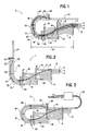
- this pressureless aligner 1 With regard to the configuration of this pressureless aligner 1, three different types are shown, respectively, in FIGS. 1, 2 and 3. Thus, in FIG. 1, the single-channel output conveyor 24 appears, substantially, parallel to the feed conveyor 2. In the context of FIG. 2, the pressureless aligner 1 adopts an "L" shaped configuration giving the bottles, at the outlet, a direction offset by an angle of 90 ° relative to at the entrance. Of course, this pressureless aligner 1 can take any intermediate shape between the positions shown in FIGS. 1 and 2. Thus, the angle formed between the feed conveyor 2 and the outlet conveyor 24 can be between 90 ° and 180 °. However, it has been found that by limiting oneself to values of 130 ° to 180 ° one obtains optimal operating conditions of the aligner without pressure for a space requirement reduced to the minimum.
- the solution shown in Figure 3 corresponds to a direction of supply and discharge of identical bottles.
- the pressureless aligner 1 takes the form of an "S", the transition conveyor 16 and the single-track exit conveyor 24 being both bent at 180 °.
- the pressureless aligner 1 in accordance with the invention, is able to adapt to any type of installation while respecting a reduced bulk.
- this pressureless aligner represented in FIG. 3.
- the output conveyor, with single track 24, composed, as its name indicates, by a single elementary pallet chain is juxtaposed with the various elementary pallet chains 3, 4, 5 forming the intermediate conveyor 6.
- This arrangement makes it possible, on the one hand, to reduce the bulk in the transverse direction of the aligner without pressure 1 and, on the other hand, to ensure the driving of certain elementary pallet chains of the intermediate conveyor 6, of the transition conveyor 16 and that of the output conveyor 24 by means of common motor means.
- the pressureless aligner which is the subject of the present invention, namely reducing its overall size, it has the additional characteristic of easy adaptability due to a modular configuration.
Landscapes
- Engineering & Computer Science (AREA)
- Mechanical Engineering (AREA)
- Attitude Control For Articles On Conveyors (AREA)
- Eye Examination Apparatus (AREA)
- Food Preservation Except Freezing, Refrigeration, And Drying (AREA)
- Blow-Moulding Or Thermoforming Of Plastics Or The Like (AREA)
- Filling Of Jars Or Cans And Processes For Cleaning And Sealing Jars (AREA)
- Manipulator (AREA)
- Jellies, Jams, And Syrups (AREA)
- Feeding Of Articles To Conveyors (AREA)
- Framework For Endless Conveyors (AREA)
Claims (7)
- Vorrichtung zum drucklosen Ausrichten von verschiedenen Gegenständen, wie Flaschen, umfassend einen Zuförderer (2) mit mehrfachen Bahnen (3, 4, 5), einen aus einer Mehrheit von mit einer bogenförmigen Führungsrampe (14) gekrönten, nebeneinanderliegenden Palettenketten (8, 9) gebildeten Zwischenförderer (6) und einen Einzelbahnabförderer (24), wobei der genannte Zwischenförderer (6) auf einen Übergangsförderer (16) mit einem bogenförmigen Weg und wenigstens zwei Bahnen endet, wobei dieser Übergangsförderer (16) stromaufwärts bezüglich des Abförderers (24) angeordnet ist, dadurch gekennzeichnet, daß der genannte Übergangsförderer (16) mit einer bogenförmigen Führungsrampe (18) gekrönt ist, die die Führung der Flaschen (11, 15) an deren der auf dem Zwischenförderer durchgeführten Führung gegenüberliegenden Seite und zwar im wesentlichen in der Mitte und an der Außenseite der vom Übergangsförderer (16) definierten Kurve (19) am stromabwärtsen Ende (20) des genannten Zwischenförderers (6) übernimmt.
- Vorrichtung zum drucklosen Ausrichten nach Anspruch 1, dadurch gekennzeichnet, daß die bogenförmige Führungsrampe (18), mit der der Übergangsförderer (16) gekrönt ist, am stromabwärtsen Ende (25) dieses letzten eine Konfiguration aufweist, die so bestimmt ist, daß den Flaschen (11) einen Weg mit einer Querkomponente vermittelt wird und diese in Richtung des Abförderers (24) gedrückt werden.
- Vorrichtung zum drucklosen Ausrichten nach Anspruch 1, dadurch gekennzeichnet, daß die Führungsrampe (18) ihr stromaufwärtses Ende (27) im wesentlichen zur Außenseite der Kurve (19) hin gebogen aufweist.
- Vorrichtung zum drucklosen Ausrichten nach Anspruch 1, dadurch gekennzeichnet, daß der Zuförderer (2) und der Abförderer (24) einen Winkel bilden, der zwischen 130° und 180° liegt.
- Vorrichtung zum drucklosen Ausrichten nach Anspruch 1, dadurch gekennzeichnet, daß sie eine S-förmige Konfiguration annimmt, wobei der Übergangsförderer (16) und der Einzelbahnabförderer (24) im wesentlichen um 180° gebogen sind.
- Vorrichtung zum drucklosen Ausrichten nach Anspruch 1 und 5, dadurch gekennzeichnet, daß der Einzelbahnabförderer (24) oder das stromabwärtse Ende (25) des Übergangsförderers (16) neben dem Zwischenförderer (6) liegt, was den Antrieb des genannten Einzelbahnabförderer (24) oder gewisser Elementarpaletketten des Übergangsförderers (16) und derjenigen des genannten Zwischenförderers (6) über gemeinsame Antriebmittel erlaubt.
- Vorrichtung zum drucklosen Ausrichten nach Anspruch 1, dadurch gekennzeichnet, daß der Zwischenförderer (6) in Vorschubrichtung (10) der Flaschen (11) geneigt ist.
Applications Claiming Priority (2)
| Application Number | Priority Date | Filing Date | Title |
|---|---|---|---|
| FR8807737 | 1988-06-07 | ||
| FR888807737A FR2632287B1 (fr) | 1988-06-07 | 1988-06-07 | Aligneur sans pression d'objets divers notamment de bouteilles |
Publications (2)
| Publication Number | Publication Date |
|---|---|
| EP0357529A1 EP0357529A1 (de) | 1990-03-07 |
| EP0357529B1 true EP0357529B1 (de) | 1994-08-10 |
Family
ID=9367140
Family Applications (1)
| Application Number | Title | Priority Date | Filing Date |
|---|---|---|---|
| EP89440049A Expired - Lifetime EP0357529B1 (de) | 1988-06-07 | 1989-06-02 | Vorrichtung zum drucklosen Ausrichten von verschiedenen Gegenständen, insbesondere von Flaschen |
Country Status (9)
| Country | Link |
|---|---|
| US (1) | US4974720A (de) |
| EP (1) | EP0357529B1 (de) |
| AT (1) | ATE109746T1 (de) |
| AU (1) | AU609308B2 (de) |
| CA (1) | CA1326465C (de) |
| DE (1) | DE68917390T2 (de) |
| DK (1) | DK275889A (de) |
| ES (1) | ES2060805T3 (de) |
| FR (1) | FR2632287B1 (de) |
Families Citing this family (4)
| Publication number | Priority date | Publication date | Assignee | Title |
|---|---|---|---|---|
| US5551551A (en) * | 1995-07-25 | 1996-09-03 | Simplimatic Engineering Company | Article combiner with multiple conveying surfaces and moving guides |
| US7322459B2 (en) * | 2006-05-01 | 2008-01-29 | Garvey Corporation | Differential speed conveyor accumulation system and method |
| CH709569A1 (de) | 2014-04-29 | 2015-10-30 | Ferag Ag | Verfahren zum Vereinzeln von Rollkörpern sowie Rollkörpervereinzelungsvorrichtung zur Durchführung des Verfahrens. |
| CN104555382A (zh) * | 2014-12-29 | 2015-04-29 | 楚天科技股份有限公司 | 一种理瓶机及联动生产线 |
Family Cites Families (8)
| Publication number | Priority date | Publication date | Assignee | Title |
|---|---|---|---|---|
| DK146440C (da) * | 1981-07-03 | 1984-03-19 | Forenede Bryggerier As | Apparat til indrangering af flere raekker flasker eller lignende genstande paa en indgangstransportoer i en enkelt raekke paa en udgangstransportoer |
| DE3234286A1 (de) * | 1982-09-16 | 1984-04-05 | Krones Ag Hermann Kronseder Maschinenfabrik, 8402 Neutraubling | Vorrichtung zum zusammenfuehren und beschleunigen eines stroms aufrecht stehender flaschen oder dgl. |
| NL8403060A (nl) * | 1984-10-08 | 1986-05-01 | Speciaalmachinefabriek Van Uit | Inlijninrichting van flessen of dergelijke. |
| DE8500522U1 (de) * | 1985-01-11 | 1986-05-07 | Rexing, Guenter, 4300 Essen | Vorrichtung zur Zusammenführung eines Flaschenstromes zu einer geschlossenen Flaschenreihe |
| GB2178389A (en) * | 1985-07-18 | 1987-02-11 | Gebo Armaturen | No-pressure aligner for items, in particular for bottles |
| DE3639834A1 (de) * | 1986-11-21 | 1988-05-26 | Holstein & Kappert Maschf | Transportvorrichtung fuer gefaesse |
| DE8706712U1 (de) * | 1987-05-09 | 1987-07-02 | Krones Ag Hermann Kronseder Maschinenfabrik, 8402 Neutraubling, De | |
| DE3715577A1 (de) * | 1987-05-09 | 1988-11-24 | Kronseder Maschf Krones | Verfahren und vorrichtung zum vereinzeln von flaschen |
-
1988
- 1988-06-07 FR FR888807737A patent/FR2632287B1/fr not_active Expired - Fee Related
-
1989
- 1989-06-02 AT AT89440049T patent/ATE109746T1/de not_active IP Right Cessation
- 1989-06-02 DE DE68917390T patent/DE68917390T2/de not_active Expired - Fee Related
- 1989-06-02 US US07/361,311 patent/US4974720A/en not_active Expired - Fee Related
- 1989-06-02 ES ES89440049T patent/ES2060805T3/es not_active Expired - Lifetime
- 1989-06-02 EP EP89440049A patent/EP0357529B1/de not_active Expired - Lifetime
- 1989-06-06 AU AU36105/89A patent/AU609308B2/en not_active Ceased
- 1989-06-06 CA CA000601935A patent/CA1326465C/fr not_active Expired - Fee Related
- 1989-06-06 DK DK275889A patent/DK275889A/da not_active Application Discontinuation
Also Published As
| Publication number | Publication date |
|---|---|
| ES2060805T3 (es) | 1994-12-01 |
| AU3610589A (en) | 1989-12-14 |
| ATE109746T1 (de) | 1994-08-15 |
| DE68917390T2 (de) | 1995-03-09 |
| FR2632287B1 (fr) | 1994-03-04 |
| CA1326465C (fr) | 1994-01-25 |
| FR2632287A1 (fr) | 1989-12-08 |
| DE68917390D1 (de) | 1994-09-15 |
| AU609308B2 (en) | 1991-04-26 |
| EP0357529A1 (de) | 1990-03-07 |
| DK275889A (da) | 1989-12-08 |
| DK275889D0 (da) | 1989-06-06 |
| US4974720A (en) | 1990-12-04 |
Similar Documents
| Publication | Publication Date | Title |
|---|---|---|
| CA2727666C (fr) | Installation de convoyage multivoies | |
| EP1224137B1 (de) | Fördervorrichtung für behälter mit einer ablenkeinrichtung | |
| EP2188199B1 (de) | Verfahren und einrichtung zur ausrichtung von beförderten produkten auf einem tisch | |
| EP3301044B1 (de) | System zur verteilung von gegenständen | |
| CA2907600A1 (fr) | Procede et systeme de transfert d'objets | |
| BE1004127A3 (fr) | Procede et dispositif pour l'amenee de bouteilles ou recipients analogues. | |
| EP0357529B1 (de) | Vorrichtung zum drucklosen Ausrichten von verschiedenen Gegenständen, insbesondere von Flaschen | |
| EP0263047B2 (de) | Förderer, für drucklosen Transport von Flaschen oder dergleichen Gegenständen | |
| FR2581048A1 (fr) | Installation de redressement de recipients presentant un goulot et un culot | |
| FR2486505A1 (fr) | Procede et dispositif pour separer les uns des autres des recipients arrivant sur plusieurs files et les repartir en une file unique | |
| EP0810963B1 (de) | Zuführvorrichtung für eine sortiervorrichtung, sortiervorrichtung mit diese zuführvorrichtung, kalibrierung und verteilvorrichtung | |
| FR2784665A1 (fr) | Station d'examen visuel de fruits | |
| FR2533200A1 (fr) | Dispositif pour regrouper et accelerer un flot de bouteilles ou analogues en position debout | |
| EP1809555B1 (de) | Vorrichtung zur übertragung von lasten zwischen mindestens zwei förderbändern | |
| FR3088315A1 (fr) | Dispositif de convoyage de produits et procede de gestion du transfert desdits produits | |
| FR2665424A1 (fr) | Dispositif de mise en couloir sans pression de recipients. | |
| FR2884506A1 (fr) | Dispositif d'entrainement pour convoyeurs ou transporteurs de charges | |
| FR2877653A1 (fr) | Dispositif de transfert de charges entre au moins deux convoyeurs ou transporteurs | |
| EP1807330B1 (de) | Behälterstaufördereinheit | |
| FR2564444A1 (fr) | Table pour l'amenee et la repartition de bouteilles ou articles analogues | |
| FR2585009A1 (fr) | Aligneur sans pression d'objets, notamment de bouteilles | |
| FR2810659A1 (fr) | Installation de remplissage et de conditionnement de corps creux | |
| BE635803A (de) | ||
| FR2810652A1 (fr) | Dispositif de realignement d'articles |
Legal Events
| Date | Code | Title | Description |
|---|---|---|---|
| PUAI | Public reference made under article 153(3) epc to a published international application that has entered the european phase |
Free format text: ORIGINAL CODE: 0009012 |
|
| AK | Designated contracting states |
Kind code of ref document: A1 Designated state(s): AT BE CH DE ES GB GR IT LI LU NL SE |
|
| 17P | Request for examination filed |
Effective date: 19900625 |
|
| 17Q | First examination report despatched |
Effective date: 19921109 |
|
| GRAA | (expected) grant |
Free format text: ORIGINAL CODE: 0009210 |
|
| AK | Designated contracting states |
Kind code of ref document: B1 Designated state(s): AT BE CH DE ES GB GR IT LI LU NL SE |
|
| REF | Corresponds to: |
Ref document number: 109746 Country of ref document: AT Date of ref document: 19940815 Kind code of ref document: T |
|
| REF | Corresponds to: |
Ref document number: 68917390 Country of ref document: DE Date of ref document: 19940915 |
|
| ITF | It: translation for a ep patent filed |
Owner name: BUGNION S.P.A. |
|
| GBT | Gb: translation of ep patent filed (gb section 77(6)(a)/1977) |
Effective date: 19940927 |
|
| REG | Reference to a national code |
Ref country code: ES Ref legal event code: FG2A Ref document number: 2060805 Country of ref document: ES Kind code of ref document: T3 |
|
| EAL | Se: european patent in force in sweden |
Ref document number: 89440049.8 |
|
| REG | Reference to a national code |
Ref country code: GR Ref legal event code: FG4A Free format text: 3013856 |
|
| PLBE | No opposition filed within time limit |
Free format text: ORIGINAL CODE: 0009261 |
|
| STAA | Information on the status of an ep patent application or granted ep patent |
Free format text: STATUS: NO OPPOSITION FILED WITHIN TIME LIMIT |
|
| 26N | No opposition filed | ||
| PGFP | Annual fee paid to national office [announced via postgrant information from national office to epo] |
Ref country code: GB Payment date: 19980526 Year of fee payment: 10 |
|
| PGFP | Annual fee paid to national office [announced via postgrant information from national office to epo] |
Ref country code: DE Payment date: 19980608 Year of fee payment: 10 |
|
| PGFP | Annual fee paid to national office [announced via postgrant information from national office to epo] |
Ref country code: AT Payment date: 19980615 Year of fee payment: 10 |
|
| PGFP | Annual fee paid to national office [announced via postgrant information from national office to epo] |
Ref country code: SE Payment date: 19980616 Year of fee payment: 10 |
|
| PGFP | Annual fee paid to national office [announced via postgrant information from national office to epo] |
Ref country code: ES Payment date: 19980619 Year of fee payment: 10 |
|
| PGFP | Annual fee paid to national office [announced via postgrant information from national office to epo] |
Ref country code: GR Payment date: 19980625 Year of fee payment: 10 |
|
| PGFP | Annual fee paid to national office [announced via postgrant information from national office to epo] |
Ref country code: NL Payment date: 19980629 Year of fee payment: 10 Ref country code: LU Payment date: 19980629 Year of fee payment: 10 |
|
| PGFP | Annual fee paid to national office [announced via postgrant information from national office to epo] |
Ref country code: CH Payment date: 19980702 Year of fee payment: 10 |
|
| PGFP | Annual fee paid to national office [announced via postgrant information from national office to epo] |
Ref country code: BE Payment date: 19980813 Year of fee payment: 10 |
|
| PG25 | Lapsed in a contracting state [announced via postgrant information from national office to epo] |
Ref country code: LU Free format text: LAPSE BECAUSE OF NON-PAYMENT OF DUE FEES Effective date: 19990602 Ref country code: GB Free format text: LAPSE BECAUSE OF NON-PAYMENT OF DUE FEES Effective date: 19990602 Ref country code: AT Free format text: LAPSE BECAUSE OF NON-PAYMENT OF DUE FEES Effective date: 19990602 |
|
| PG25 | Lapsed in a contracting state [announced via postgrant information from national office to epo] |
Ref country code: ES Free format text: LAPSE BECAUSE OF NON-PAYMENT OF DUE FEES Effective date: 19990603 |
|
| PG25 | Lapsed in a contracting state [announced via postgrant information from national office to epo] |
Ref country code: SE Free format text: THE PATENT HAS BEEN ANNULLED BY A DECISION OF A NATIONAL AUTHORITY Effective date: 19990629 |
|
| PG25 | Lapsed in a contracting state [announced via postgrant information from national office to epo] |
Ref country code: LI Free format text: LAPSE BECAUSE OF NON-PAYMENT OF DUE FEES Effective date: 19990630 Ref country code: GR Free format text: LAPSE BECAUSE OF NON-PAYMENT OF DUE FEES Effective date: 19990630 Ref country code: CH Free format text: LAPSE BECAUSE OF NON-PAYMENT OF DUE FEES Effective date: 19990630 Ref country code: BE Free format text: LAPSE BECAUSE OF NON-PAYMENT OF DUE FEES Effective date: 19990630 |
|
| BERE | Be: lapsed |
Owner name: S.A. GEBO INDUSTRIES Effective date: 19990630 |
|
| PG25 | Lapsed in a contracting state [announced via postgrant information from national office to epo] |
Ref country code: NL Free format text: LAPSE BECAUSE OF NON-PAYMENT OF DUE FEES Effective date: 20000101 |
|
| GBPC | Gb: european patent ceased through non-payment of renewal fee |
Effective date: 19990602 |
|
| REG | Reference to a national code |
Ref country code: CH Ref legal event code: PL |
|
| EUG | Se: european patent has lapsed |
Ref document number: 89440049.8 |
|
| NLV4 | Nl: lapsed or anulled due to non-payment of the annual fee |
Effective date: 20000101 |
|
| PG25 | Lapsed in a contracting state [announced via postgrant information from national office to epo] |
Ref country code: DE Free format text: LAPSE BECAUSE OF NON-PAYMENT OF DUE FEES Effective date: 20000503 |
|
| REG | Reference to a national code |
Ref country code: ES Ref legal event code: FD2A Effective date: 20010503 |
|
| PG25 | Lapsed in a contracting state [announced via postgrant information from national office to epo] |
Ref country code: IT Free format text: LAPSE BECAUSE OF NON-PAYMENT OF DUE FEES;WARNING: LAPSES OF ITALIAN PATENTS WITH EFFECTIVE DATE BEFORE 2007 MAY HAVE OCCURRED AT ANY TIME BEFORE 2007. THE CORRECT EFFECTIVE DATE MAY BE DIFFERENT FROM THE ONE RECORDED. Effective date: 20050602 |