EP0356672B1 - Ferroelektrische, chirale, smektische Flüssigkristall-Zusammensetzung und Vorrichtung zu deren Anwendung - Google Patents
Ferroelektrische, chirale, smektische Flüssigkristall-Zusammensetzung und Vorrichtung zu deren Anwendung Download PDFInfo
- Publication number
- EP0356672B1 EP0356672B1 EP89112758A EP89112758A EP0356672B1 EP 0356672 B1 EP0356672 B1 EP 0356672B1 EP 89112758 A EP89112758 A EP 89112758A EP 89112758 A EP89112758 A EP 89112758A EP 0356672 B1 EP0356672 B1 EP 0356672B1
- Authority
- EP
- European Patent Office
- Prior art keywords
- liquid crystal
- single bond
- crystal composition
- prepared
- composition
- Prior art date
- Legal status (The legal status is an assumption and is not a legal conclusion. Google has not performed a legal analysis and makes no representation as to the accuracy of the status listed.)
- Expired - Lifetime
Links
- 0 CC(C)C1CNC(c2ccc(*)cc2)NC1 Chemical compound CC(C)C1CNC(c2ccc(*)cc2)NC1 0.000 description 58
- UAEPNZWRGJTJPN-UHFFFAOYSA-N CC1CCCCC1 Chemical compound CC1CCCCC1 UAEPNZWRGJTJPN-UHFFFAOYSA-N 0.000 description 1
- YWNIWCALGHPPIU-UHFFFAOYSA-N CCCCCCCCC(C=C1)=CCC1=C Chemical compound CCCCCCCCC(C=C1)=CCC1=C YWNIWCALGHPPIU-UHFFFAOYSA-N 0.000 description 1
- VMRGTNYVHJBEMD-UHFFFAOYSA-N CCCCCCCCC(CC1)(CCC1c1ccccc1)C#N Chemical compound CCCCCCCCC(CC1)(CCC1c1ccccc1)C#N VMRGTNYVHJBEMD-UHFFFAOYSA-N 0.000 description 1
- QFXBYIOITAOSCX-UHFFFAOYSA-N CCNC(CC1)(CCC1[O](c(cc1)ccc1O)=O)[Zn] Chemical compound CCNC(CC1)(CCC1[O](c(cc1)ccc1O)=O)[Zn] QFXBYIOITAOSCX-UHFFFAOYSA-N 0.000 description 1
Images


Classifications
-
- C—CHEMISTRY; METALLURGY
- C09—DYES; PAINTS; POLISHES; NATURAL RESINS; ADHESIVES; COMPOSITIONS NOT OTHERWISE PROVIDED FOR; APPLICATIONS OF MATERIALS NOT OTHERWISE PROVIDED FOR
- C09K—MATERIALS FOR MISCELLANEOUS APPLICATIONS, NOT PROVIDED FOR ELSEWHERE
- C09K19/00—Liquid crystal materials
- C09K19/04—Liquid crystal materials characterised by the chemical structure of the liquid crystal components, e.g. by a specific unit
- C09K19/42—Mixtures of liquid crystal compounds covered by two or more of the preceding groups C09K19/06 - C09K19/40
- C09K19/46—Mixtures of liquid crystal compounds covered by two or more of the preceding groups C09K19/06 - C09K19/40 containing esters
-
- C—CHEMISTRY; METALLURGY
- C09—DYES; PAINTS; POLISHES; NATURAL RESINS; ADHESIVES; COMPOSITIONS NOT OTHERWISE PROVIDED FOR; APPLICATIONS OF MATERIALS NOT OTHERWISE PROVIDED FOR
- C09K—MATERIALS FOR MISCELLANEOUS APPLICATIONS, NOT PROVIDED FOR ELSEWHERE
- C09K19/00—Liquid crystal materials
- C09K19/04—Liquid crystal materials characterised by the chemical structure of the liquid crystal components, e.g. by a specific unit
- C09K19/06—Non-steroidal liquid crystal compounds
- C09K19/34—Non-steroidal liquid crystal compounds containing at least one heterocyclic ring
- C09K19/3441—Non-steroidal liquid crystal compounds containing at least one heterocyclic ring having nitrogen as hetero atom
Definitions
- the present invention relates to a liquid crystal composition used in a liquid crystal display device, a liquid crystal-optical shutter, etc., more particularly to a novel liquid crystal composition with improved responsiveness to an electric field and a liquid crystal device using the liquid crystal composition.
- liquid crystal devices have been used as an electro-optical device in various fields.
- Most liquid crystal devices which have been put into practice use TN (twisted nematic) type liquid crystals, as shown in "Voltage-Dependent Optical Activity of a Twisted Nematic Liquid Crystal” by M. Schadt and W. Helfrich “Applied Physics Letters” Vol. 18, No. 4 (Feb. 15, 1971) pp. 127-128.
- an electrode arrangement wherein scanning electrodes and signal electrodes are arranged in a matrix, and for driving, a multiplex driving scheme is adopted wherein an address signal is sequentially, periodically and selectively applied to the scanning electrodes and prescribed data signals are selectively applied in parallel to the signal electrodes in synchronism with the address signal.
- a certain electric field is applied to regions where a scanning electrode is selected and signal electrodes are not selected or regions where a scanning electrode is not selected and a signal electrode is selected (which regions are so called "half-selected points"). If the difference between a voltage applied to the selected points and a voltage applied to the half-selected points is sufficiently large, and a voltage threshold level required for allowing liquid crystal molecules to be aligned or oriented perpendicular to an electric field is set to a value therebetween, display devices normally operate.
- liquid crystal molecules are horizontally oriented with respect to the electrode surface as stable state and is vertically oriented with respect to the electrode surface only when an electric field is effectively applied) is driven (i.e. repeatedly scanned) by making use of a time storage effect.
- the voltage averaging method, the two-frequency driving method, the multiple matrix method, etc. has been already proposed.
- any method is not sufficient to overcome the above-mentioned drawbacks. As a result, it is the present state that the development of large image area or high packaging density in respect to display elements is delayed because it is difficult to sufficiently increase the number of scanning lines.
- liquid crystal devices having bistability have been proposed by Clark and Lagerwall (e.g. Japanese Laid-Open Patent Appln. No. 56-107216, U.S.P. No. 4367924, etc.).
- ferroelectric liquid crystals having chiral smectic C-phase (SmC * ) or H-phase (SmH * ) are generally used as the liquid crystals having bistability. These liquid crystals have bistable states of first and second stable states with respect to an electric field applied thereto.
- the bistable liquid crystal molecules are oriented to first and second optically stable states with respect to one and the other electric field vectors, respectively. Further, this type of liquid crystal has a property (bistability) of assuming either one of the two stable states in response to an applied electric and retaining the resultant state in the absence of an electric field.
- ferroelectric liquid crystal (hereinafter sometimes abbreviated as "FLC") has an excellent property, i.e., a high-speed responsiveness. This is because the spontaneous polarization of the ferroelectric liquid crystal and an applied electric field directly interact with each other to induce transition of orientation states. The resultant response speed is faster than the response speed due to the interaction between dielectric anisotropy and an electric field by 3 to 4 digits.
- a ferroelectric liquid crystal potentially has very excellent characteristics, and by making use of these properties, it is possible to provide essential improvements to many of the above-mentioned problems with the conventional TN-type devices. Particularly, the application to a high-speed optical shutter and a display of a high density and a large picture is expected.
- a simple matrix display apparatus including a device comprising such a ferroelectric liquid crystal layer between a pair of substrates may be driven according to a driving method as disclosed in, e.g., Japanese Laid-Open Patent Applications Nos. 193426/1984, 193427/1984, 156046/1985 and 156047/1985.
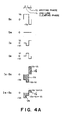
- Figures 4A and 4B are waveform diagrams showing driving voltage waveforms adopted in driving a ferroelectric liquid crystal panel as an embodiment of the liquid crystal device according to the present invention.
- Figure 5 is a plan view of such a ferroelectric liquid crystal panel 51 having a matrix electrode structure.
- the panel 51 comprises scanning lines 52 and data lines 53 intersecting with the scanning lines. Each intersection comprises a ferroelectric liquid crystal disposed between a scanning line 52 and a data line 53 to form a pixel.
- S s is shown a selection scanning signal waveform applied to a selected scanning line
- S N is shown a non-selection scanning signal waveform applied to a non-selected scanning line
- Is is shown a selection data signal waveform (providing a black display state) applied to a selected data line
- at IN is shown a non-selection data signal waveform applied to a non-selected data line.
- FIG. 4B shows a time-serial waveform used for providing a display state as shown in Figure 6.
- a minimum duration At of a single polarity voltage applied to a pixel on a selected scanning line corresponds to the period of a writing phase t 2 , and the period of a one-line clearing phase t 1 is set to 2At.
- V s , V and At in the driving waveforms shown in Figures 4A and 4B are determined depending on switching characteristics of a ferroelectric liquid crystal material used.
- Figure 7 shows a V - T characteristic, i.e., a change in transmittance T when a driving voltage denoted by (V S +V I ) is changed while a bias ratio as mentioned hereinbelow is kept constant.
- On the right side of Figure 7 is shown a result when the voltage (IN-S S ) shown in Figure 4 is applied to a pixel concerned, and on the left side of Figure 7 is shown a result when the voltage (l s -S s ) is applied to a pixel concerned, respectively while increasing the voltage (V S +V I ).
- a voltage V denotes the absolute value of (V S +V I ) required for switching from a white state to a black state by applying a voltage signal V B 2 shown in Figure 4A
- a voltage V 2 denotes the absolute value of (V S +V I ) required for switching (resetting) a black state to a white state by applying a voltage V R at IN - S s
- a voltage V 3 is the value of (V S +V I ) beyond which a pixel concerned written in white is unexpectedly inverted into a black state.
- a relationship of V 2 ⁇ V ⁇ V 3 holds.
- the voltage V may be referred to as a threshold voltage in actual drive and the voltage V 3 may be referred to as a crosstalk voltage.
- a crosstalk voltage V 3 is generally present in actual matrix drive of a ferroelectric liquid crystal device.
- AV (V 3 -V 1 ) provides a range of
- allowing a matrix drive and may be referred to as a (driving) voltage margin, which is preferably large enough. It is of course possible to increase the value of V 3 and thus ⁇ V ( V 3 -Vi) by increasing the bias ratio (i.e., by causing the bias ratio to approach a unity).
- a large bias ratio corresponds to a large amplitude of a data signal and leads to an increase in flickering and a lower contrast, thus being undesirable in respect of image quality.
- a bias ratio of about 1/3 - 1/4 was practical.
- the voltage margin ⁇ V strongly depends on the switching characteristics of a liquid crystal material used, and it is needless to say that a liquid crystal material providing a large ⁇ V is very advantageous for matrix drive.
- driving voltage margin AV The upper and lower limits of application voltages and a difference therebetween (driving voltage margin AV) by which selected pixels are written in two states of "black” and “white” and non-selected pixels can retain the written "black” and “white” states at a constant temperature as described above, vary depending on and are inherent to a particular liquid crystal material used. Further, the driving margin is deviated according to a change in environmental temperature, so that optimum driving voltages should be set in an actual display apparatus according to a liquid crystal material used and an environmental temperature.
- ferroelectric liquid crystal molecules under such non-helical conditions are disposed in succession so that their directors (longer molecular axes) are gradually twisted between the substrates and do not show a uniaxial orientation or alignment (i.e., in a splay alignment state).
- a problem in this case is a low transmittance through the liquid crystal layer.
- Transmitted light intensity I through a liquid crystal is given by the following equation with respect to the incident light intensity lo under cross nicols when the uniaxial alignment of the molecules is assumed: wherein An denotes the refractive index anisotropy of the FLC; d, the cell thickness; x, the wavelength of the incident light; and ea, a half of the angle between two stable states (tilt angle).
- a torque FP s acting on FLC molecules involved in switching of states and a torque ⁇ acting on FLC molecules relating to the AC stabilization effect are respectively proportional to physical properties as shown in the following formulas:
- the above formula (3) apparently shows that the sign and absolute value of ⁇ of the FLC play an important role.
- Figure 8 attached hereto shows the change of ⁇ a versus Vrms experimentally measured for 4 FLCs having different values of ⁇ .
- the measurement was conducted under application of AC rectangular pulses of 60 KHz so as to remove the influence of P s .
- the curves (I) - (IV) correspond to the results obtained by using FLCs showing the following ⁇ values Qualitatively, the order of ⁇ was (I) ⁇ (II) ⁇ (III) ⁇ (IV).
- the transmittances obtained by using the liquid crystals (I) and (III) were 15 % for (I) and 6 % for (III) (under application of rectangular AC waveforms of 60 kHz and ⁇ 8 V), thus showing a clear difference.
- the display characteristics of an SSFLC can be remarkably changed by controlling the properties relating to ⁇ and P s .
- a ferroelectric liquid crystal composition having a negatively large ⁇ it is most effective to include a compound having a negative ⁇ with a large absolute value.
- a compound having a negatively large ⁇ by introducing a halogen or cyano group in a shorter axis direction of a molecule or by introducing a heterocyclic skeleton in a molecule.
- R and R' respectively denote an alkyl group. These may be classified roughly into three groups including compounds having a negatively small ⁇ (
- An object of the present invention is to provide a chiral smectic liquid crystal composition having a large driving voltage margin adapted for providing a practical ferroelectric liquid crystal device and a wide driving voltage margin affording satisfactory drive of entire pixels even when some degree of temperature fluctuation is present over a display area comprising the pixels of a liquid crystal device.
- Another object of the present invention is to provide a liquid crystal composition further containing a mesomorphic compound having a negative dielectric anisotropy to show an AC stabilization effect providing remarkably improved display characteristics.
- a further object of the present invention is to provide a liquid crystal device using such a liquid crystal composition and showing improved driving and display characteristics.
- a ferroelectric chiral smectic liquid crystal composition comprising
- a ferroelectric liquid crystal composition as described above further comprising a mesomorphic compound having a negative dielectric anisotropy, which is preferably one having a ⁇ ⁇ -2, more preferably ⁇ ⁇ -5 , most preferably ⁇ ⁇ -10 .
- the present invention further provides a liquid crystal device comprising a pair of substrates and such a ferroelectric liquid crystal composition as described above disposed between the electrode plates.
- optically active compounds represented by the above-mentioned general formula (I) may include those represented by the following formulas (I-a) to (I-I).
- R 1 and R 2 are the same as in the general formula (I).
- Preferred examples of R 1 and R 2 may include those of the following (I-i) to (I-iii).
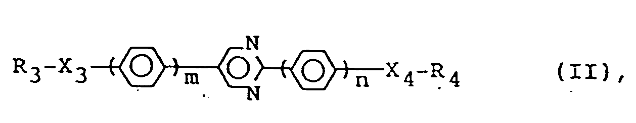
- preferred examples of the compounds represented by the above-mentioned general formula (II) may include those represented by the following formulas (II-a) to (II-e).
- R 3 , R 4 , X 3 and X 4 are respectively the same as in the general formula (II).
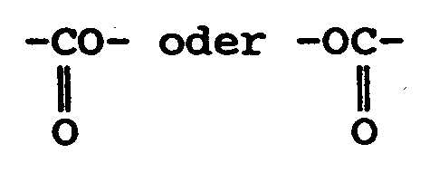
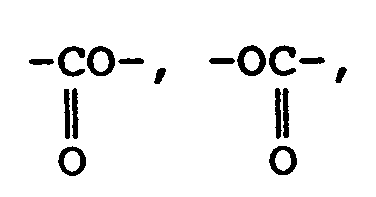
- Preferred examples of X 3 and X 4 may include the following combinations (II-i) to (II-viii):
- the compounds represented by the formula (I) may be synthesized through processes as disclosed by, e.g., Japanese Laid-Open patent Applications (KOKAI) 200972/1986, 200973/1986, 215372/1986 and 291574/1986.
- KKAI Japanese Laid-Open patent Applications
- R 1 , R 2 and X 2 are the same as defined above.
- the compounds represented by the formula (II) may be synthesized through process as disclosed by, e.g., East Germany Patent No. 95892 (1973) and Japanese Patent Publication (KOKOKU) 5434/1987. More specifically, for example, compounds represented by the formula: may be synthesized through the following reaction scheme: R 3 , R 4 , p and q are the same as defined above.
- the ferroelectric chiral smectic liquid crystal composition according to the present invention further comprises a mesomorphic compound having a negative dielectric anisotropy, which is preferably selected from those represented by the following formulas (III-1) to (III-5):
- the alkyl groups Ra - Ro may respectively have 1 - 18 carbon atoms, preferably 4 - 16 carbon atoms, further preferably 6 - 12 carbon atoms.
- mesomorphic compounds represented by the general formulas (III-1) to (III-5) may respectively include those denoted by the structural formulas shown below.
- the mesomorphic compound having a negative dielectric anisotropy ⁇ may preferably have ⁇ ⁇ -2, preferably Ae ⁇ -5, further preferably ⁇ ⁇ -10.
- the liquid crystal composition according to the present invention may be obtained by mixing at least one species of the compound represented by the formula (I), at least one species of the compound represented by the formula (II), optionally at least one species of a mesomorphic compound having a negative dielectric anisotropy and another mesomorphic compound in appropriate proportions.
- the liquid crystal composition according to the present invention may preferably be formulated as a ferroelectric liquid crystal composition, particularly a ferroelectric chiral smectic liquid crystal composition.
- liquid crystal composition it is desirable to mix 1 - 300 wt. parts each, preferably 2 - 100 wt. parts each, of a compound represented by the formula (I) and a compound represented by the formula (II) with 100 wt. parts of another mesomorphic compound as mentioned above which can be composed of two or more species.
- the two or more species of the compound of the formula (I) or (II) may be used in a total amount of 1 - 500 wt. parts, preferably 2 - 100 wt. parts, per 100 wt. parts of another mesomorphic compound as described above which can be composed of two or more species.
- the weight ratio of the compound of the formula (I)/the compound of the formula (II) may desirably be 1/300 - 300/1, preferably 1/50 - 50/1.
- the weight ratio of the total amount of the compounds of the formula (I)/the total amounts of the compounds of the formula (II) may desirably be 1/500 - 500/1, preferably 1/50 - 50/1.
- the total amounts of the compounds of the formulas (I) and (II) may desirably be 2 - 600 wt. parts, preferably 4 - 200 wt. parts, when one species each is selected from the formulas (I) and (II), or 2 - 1000 wt. parts, preferably 4 - 200 wt. parts, when two or more species are selected from at least one of the formulas (I) and (II), respectively, with respect to 100 wt. parts of the above-mentioned another mesomorphic compound which may be composed of two or more species.
- a mesomorphic compound having a negative dielectric anisotropy as described above can be contained in a proportion of 1 - 98 wt. % of the liquid crystal composition of the present invention so as to provide a composition having a negative dielectric anisotropy.
- the total of the compounds of the formulas (I) and (II) and the mesomorphic compound having a negative dielectric anisotropy can constitute 3 - 100 wt. % of the liquid crystal composition of the present invention.
- the ferroelectric liquid crystal device according to the present invention may preferably be prepared by heating the liquid crystal composition prepared as described above into an isotropic liquid under vacuum, filling a blank cell comprising a pair of oppositely spaced electrode plates with the composition, gradually cooling the cell to form a liquid crystal layer and restoring the normal pressure.
- Figure 1 is a schematic sectional view of an embodiment of the ferroelectric liquid crystal device prepared as described above for explanation of the structure thereof.
- the ferroelectric liquid crystal device includes a ferroelectric liquid crystal layer 1 disposed between a pair of glass substrates 2 each having thereon a transparent electrode 3 and an insulating alignment control layer 4.
- Lead wires 6 are connected to the electrodes so as to apply a driving voltage to the liquid crystal layer 1 from a power supply 7.
- a pair of polarizer 8 are disposed so as to modulate incident light lo from a light source 9 in cooperation with the liquid crystal 1 to provide modulated light I.
- Each of two glass substrates 2 is coated with a transparent electrode 3 comprising a film of ln 2 0 3 , Sn0 2 or ITO (indium-tin-oxide) to form an electrode plate.
- a transparent electrode 3 comprising a film of ln 2 0 3 , Sn0 2 or ITO (indium-tin-oxide) to form an electrode plate.
- an insulating alignment control layer 4 is formed by rubbing a film of a polymer such as polyimide with gauze or acetate fiber-planted cloth so as to align the liquid crystal molecules in the rubbing direction.
- the alignment control layer of two layers, e.g., by first forming an insulating layer of an inorganic material such as silicon nitride, silicon nitride containing hydrogen, silicon carbide, silicon carbide containing hydrogen, silicon oxide, boron nitride, boron nitride containing hydrogen, cerium oxide, aluminum oxide,, zirconium oxide, titanium oxide, or magnesium fluoride, and forming thereon an alignment control layer of an organic insulating material, such as polyvinyl alcohol, polyimide, polyamide-imide, polyester-imide, polyparaxylylene, polyester, polycarbonate, polyvinyl acetal, polyvinyl chloride, polyvinyl acetate, polyamide, polystyrene, cellulose resin, melamine resin, urea resin, acrylic resin, or photoresist resin.
- an inorganic material such as silicon nitride, silicon nitride containing hydrogen, silicon carbide, silicon carbide containing hydrogen, silicon
- inorganic insulating alignment control layer may be formed by vapor deposition, while an organic insulating alignment control layer may be formed by applying a selection of an organic insulating material or a precursor thereof in a concentration of 0.1 to 20 wt. %, preferably 0.2 - 10 wt. %, by spinner coating, dip coating, screen printing, spray coating or roller coating, followed by curing or hardening under prescribed hardening condition (e.g., by heating).
- the insulating alignment control layer may have a thickness of ordinarily 30 ⁇ - 1 micron, preferably 30 - 3000 ⁇ , further preferably 50 - 1000 ⁇ .
- the two glass substrates 2 with transparent electrodes 3 (which may be inclusively referred to herein as "electrode plates") and further with insulating alignment control layers 4 thereof are held to have a prescribed (but arbitrary) gap with a spacer 5.
- a cell structure with a prescribed gap may be formed by sandwiching spacers of silica beads or alumina beads having a prescribed diameter with two glass plates, and then sealing the periphery thereof with, e.g., an epoxy adhesive.
- a polymer film or glass fiber may also be used as a spacer.
- a ferroelectric liquid crystal is sealed up to provide a ferroelectric liquid crystal layer 1 in a thickness of generally 0.5 to 20 microns, preferably 1 to 5 microns.
- the ferroelectric liquid crystal provided by the composition of the present invention may desirably assume a SmC * phase (chiral smectic C phase) in a wide temperature range including room temperature (particularly, broad in a lower temperature side) and also shows wide drive voltage margin and drive temperature margin when contained in a device.
- SmC * phase chiral smectic C phase
- the ferroelectric liquid crystal may show a phase transition series comprising isotropic phase - Ch phase (cholesteric phase) - SmA phase (smectic A phase) - SmC * phase (chiral smectic C phase) on temperature decrease.
- the transparent electrodes 3 are connected to the external power supply 7 through the lead wires 6. Further, outside the glass substrates 2, polarizers 8 are applied.
- the device shown in Figure 1 is of a transmission type and is provided with a light source 9.
- FIG. 2 is a schematic illustration of a ferroelectric liquid crystal cell (device) for explaining operation thereof.
- Reference numerals 21 a and 21 b denote substrates (glass plates) on which a transparent electrode of, e.g., ln 2 0 3 , Sn0 2 , ITO (indium-tin-oxide), etc., is disposed, respectively.
- a liquid crystal of an SmC *- phase (chiral smectic C phase) in which liquid crystal molecular layers 22 are aligned perpendicular to surfaces of the glass plates is hermetically disposed therebetween.
- Full lines 23 show liquid crystal molecules.
- Each liquid crystal molecule 23 has a dipole moment (P1) 24 in a direction perpendicular to the axis thereof.
- the liquid crystal molecules 23 continuously form a helical structure in the direction of extension of the substrates.
- a voltage higher than a certain threshold level is applied between electrodes formed on the substrates 21 a and 21 b, a helical structure of the liquid crystal molecule 23 is unwound or released to change the alignment direction of respective liquid crystal molecules 23 so that the dipole moments (P1) 24 are all directed in the direction of the electric field.
- the liquid crystal molecules 23 have an elongated shape and show refractive anisotropy between the long axis and the short axis thereof.
- the liquid crystal cell when, for instance, polarizers arranged in a cross nicol relationship, i.e., with their polarizing directions crossing each other, are disposed on the upper and the lower surfaces of the glass plates, the liquid crystal cell thus arranged functions as a liquid crystal optical modulation device of which optical characteristics vary depending upon the polarity of an applied voltage.
- the helical structure of the liquid crystal molecules is unwound to provide a non-helical structure even in the absence of an electric field, whereby the dipole mount assumes either of the two states, i.e., Pa in an upper direction 34a or Pb in a lower direction 34b as shown in Figure 3, thus providing a bistable condition.
- an electric field Ea or Eb higher than a certain threshold level and different from each other in polarity as shown in Figure 3 is applied to a cell having the above-mentioned characteristics, the dipole moment is directed either in the upper direction 34a or in the lower direction 34b depending on the vector of the electric field Ea or Eb.
- the liquid crystal molecules are oriented in either of a first stable state 33a and a second stable state 33b.
- the device may be driven by a driving method as disclosed in Japanese Laid-Open Patent Applications (KOKAI) Nos. 193426/1984, 193427/1984, 156046/1985, 156047/1985, etc.
- KKAI Japanese Laid-Open Patent Applications
- ferroelectric liquid crystal device may for example be driven by a driving embodiment as described hereinbefore with reference to Figures 3 to 7.
- a liquid crystal composition 1-A was prepared by mixing the following compounds in respectively indicated proportions.
- a liquid crystal composition 1-B was prepared by mixing the following Example compounds Nos. 1-6 and 2-23 with the above prepared composition 1-A.
- the above-prepared liquid crystal composition 1-B was used to prepare a liquid crystal device in combination with a blank cell prepared in the following manner.
- Two 1.1 mm-thick glass plates were provided and respectively coated with an ITO film to form an electrode for voltage application, which was further coated with an insulating layer of vapor-deposited Si0 2 .
- the insulating layer was further coated with a 1.0 %-solution of polyimide resin precursor (SP-510, available from Toray K.K.) in dimethylacetoamide by a spinner coater rotating at 3000 rpm for 15 seconds. Thereafter, the co ting film was subjected to heat curing at 300 °C for 60 min. to obtain about 120 A-thick film.
- the coating film was rubbed with acetate fiber-planted cloth. The thus treated two glass plates were washed with isopropyl alcohol.
- silica beads with an average particle size of 1.5 microns were dispersed on one of the glass plates, the two glass plates were applied to each other with a bonding sealing agent (Lixon Bond, available from Chisso K.K.) so that their rubbed directions were parallel to each other and heated at 100 °C for 60 min. to form a blank cell.
- the cell gap was found to be about 1.5 microns as measured by a Berek compensator.
- the above-prepared liquid crystal composition 1-B was heated into an isotropic liquid, and injected into the above prepared cell under vacuum and, after sealing, was gradually cooled at a rate of 20 °C/hour to 25 °C to prepare a ferroelectric liquid crystal device.
- the temperature difference capable of driving (hereinafter called “(driving) temperature margin) was ⁇ 3.0 °C.
- contrast of 9 was attained at 25 °C during the driving.
- a liquid crystal composition 1-C was prepared by omitting Example compound No. 2-23 from the liquid crystal composition 1-B, i.e., by adding only Example compound No. 1-6 to the liquid crystal composition 1-A, and a liquid crystal composition 1-D was prepared by omitting Example compound No. 1-6 from the composition 1-B, i.e., by adding only Example compound No. 2-23 to the composition 1-A.
- Ferroelectric liquid crystal devices 1-A, 1-C and 1-D were prepared by using the compositions 1-A, 1-C and 1-D, respectively, instead of the composition 1-B, and subjected to measurement of driving voltage margin AV, otherwise in the same manner as in Example 1. The results are shown below.
- the driving temperature margin with respect to 25 °C was ⁇ 2.2 °C for 1-A, ⁇ 2.5 °C for 1-C and ⁇ 2.4 °C for 1-D.
- the ferroelectric liquid crystal device containing the liquid crystal composition 1-B according to the resent invention provided wider driving voltage and temperature margins and showed a better performance of retaining good images in resistance to changes in environmental temperature and cell gap.
- a liquid crystal composition 2-B was prepared by mixing the following example compounds in the indicated proportions with the liquid crystal composition 1-A prepared in Example 1.
- a ferroelectric liquid crystal device was prepared in the same manner as in Example 1 except that the above liquid crystal composition 2-B was used, and the device was subjected to measurement of driving voltage margin and observation of switching states. In the device, a mono domain with a good and uniform alignment characteristic was observed. The results of the measurement are shown below.
- the driving temperature margin with respect to 25 °C was ⁇ 3.3 °C.
- a contrast of 8 was attained during the drive at the temperature.
- a liquid crystal composition 2-C was prepared by omitting Example compound No. 2-57 from the liquid crystal composition 2-B, i.e., by adding only Example compounds Nos. 1-5 and 1-17 to the liquid crystal composition 1-A, and a liquid crystal composition 2-D was prepared by omitting Example compounds Nos. 1-5 and 1-17 from the composition 2-B, i.e., by adding only Example compound No. 2-57 to the composition 1-A.
- Ferroelectric liquid crystal devices 1-A, 2-C and 2-D were prepared by using the compositions 1-A, 2-C and 2-D, respectively, instead of the composition 1-B, and subjected to measurement of driving voltage margin AV, otherwise in the same manner as in Example 1. The results are shown below.
- the driving temperature margin with respect to 25 °C was ⁇ 2.2 °C for 1-A, ⁇ 2.6 °C for 2-C and ⁇ 2.4 °C for 2-D.
- the ferroelectric liquid crystal device containing he liquid crystal composition 2-B according to the present invention provided wider driving voltage and temperature margins and showed a better performance of retaining good images in resistance to changes in environmental temperature and cell gap.
- a liquid crystal composition 3-B was prepared by mixing the following example compounds in the indicated proportions with the liquid crystal composition 1-A prepared in Example 1.
- a ferroelectric liquid crystal device was prepared in the same manner as in Example 1 except that the above liquid crystal composition 3-B was used, and the device was subjected to measurement of driving voltage margin and observation of switching states. In the device, a monodomain with a good and uniform alignment characteristic was observed. The results of the measurement are shown below.
- the driving temperature margin with respect to 25 °C was ⁇ 3.7 °C.
- a contrast of 10 was attained during the drive at the temperature.
- a liquid crystal composition 3-C was prepared by omitting Example compound No. 2-82 from the liquid crystal composition 3-B, i.e., by adding only Example compound No. 1-4 to the liquid crystal composition 1-A, and a liquid crystal composition 3-D was prepared by omitting Example compound No. 1-4 from the composition 3-B, i.e., by adding only Example compound No. 2-82 to the composition 1-A.
- Ferroelectric liquid crystal devices 1-A, 3-C and 3-D were prepared by using the compositions 1-A, 3-C and 3-D, respectively, instead of the composition 1-B, and subjected to measurement of driving voltage margin AV, otherwise in the same manner as in Example 1. The results are shown below.
- the driving temperature margin with respect to 25 °C was ⁇ 2.2 °C for 1-A, ⁇ 2.8 °C for 3-C and ⁇ 2.7 °C for 3-D.
- the ferroelectric liquid crystal device containing the liquid crystal composition 3-B according to the present invention provided wider driving voltage and temperature margins and showed a better performance of retaining good images in resistance to changes in environmental temperature and cell gap.
- a liquid crystal composition 4-B was prepared by mixing the following example compounds in the indicated proportions with the liquid crystal composition 1-A prepared in Example 1.
- a ferroelectric liquid crystal device was prepared in the same manner as in Example 1 except that the above liquid crystal composition 4-B was used, and the device was subjected to measurement of driving voltage margin and observation of switching states. In the device, a monodomain with a good and uniform alignment characteristic was observed. The results of the measurement are shown below.
- the driving temperature margin with respect to 25 °C was ⁇ 3.1 °C.
- a contrast of 9 was attained during the drive at the temperature.
- a liquid crystal composition 4-C was prepared by omitting Example compound No. 2-9 from the liquid crystal composition 4-B, i.e., by adding only Example compound No. 1-15 to the liquid crystal composition 1-A, and a liquid crystal composition 4-D was prepared by omitting Example compound No. 1-15 from the composition 4-B, i.e., by adding only Example compound No. 2-9 to the composition 1-A.
- Ferroelectric liquid crystal devices 1-A, 4-C and 4-D were prepared by using the compositions 1-A, 4-C and 4-D, respectively, instead of the composition 1-B, and subjected to measurement of driving voltage margin AV, otherwise in the same manner as in Example 1. The results are shown below.
- the driving temperature margin with respect to 25 °C was ⁇ 2.2 °C for 1-A, ⁇ 2.5 °C for 4-C and ⁇ 2.4 °C for 4-D.
- the ferroelectric liquid crystal device containing the liquid crystal composition 4-B according to the present invention provided wider driving voltage and temperature margins and showed a better performance of retaining good images in resistance to changes in environmental temperature and cell gap.
- a liquid crystal composition 5-A was prepared by mixing the following compounds in respectively indicated proportions.
- a liquid crystal composition 5-B was prepared by mixing the following Example compounds Nos. 1-3, 2-73 and 2-83 with the above prepared composition 5-A.
- a ferroelectric liquid crystal device 5-B was prepared in the same manner as in Example 1 except that the liquid crystal composition 5-B was used instead of the composition 1-B.
- the device was subjected to measurement of driving voltage margin and observation of switching states. In the device, a monodomain with a good and uniform alignment characteristic was observed. The results of the measurement are shown below.
- the driving temperature margin with respect to 25 °C was ⁇ 4.1 °C.
- a contrast of 8 was attained during the drive at the temperature.
- a liquid crystal composition 5-C was prepared by omitting Example compounds Nos. 2-73 and 2-83 from the liquid crystal composition 5-B prepared in Example 5, i.e., by adding only Example compound No. 1-3 to the liquid crystal composition 5-A, and a liquid crystal composition 5-D was prepared by omitting Example compound No. 1-3 from the composition 5-B, i.e., by adding only Example compounds Nos. 2-73 and 2-83 to the composition 5-A.
- Ferroelectric liquid crystal devices 5-A, 5-C and 5-D were prepared by using the compositions 5-A, 5-C and 5-D, respectively, instead of the composition 1-B, and subjected to measurement of driving voltage margin AV, otherwise in the same manner as in Example 1. The results are shown below.
- the driving temperature margin with respect to 25 °C was ⁇ 2.5 °C for 5-A, ⁇ 2.7 °C for 5-C and ⁇ 2.8 °C for 5-D.
- the ferroelectric liquid crystal device containing the liquid crystal composition 5-B according to the present invention provided wider driving voltage and temperature margins and showed a better performance of retaining good images in resistance to changes in environmental temperature and cell gap.
- a liquid crystal composition 6-B was prepared by mixing the following example compounds in the indicated proportions with the liquid crystal composition 5-A prepared in Example 5.
- a ferroelectric liquid crystal device was prepared in the same manner as in Example 1 except that the above liquid crystal composition 6-B was used, and the device was subjected to measurement of driving voltage margin and observation of switching states. In the device, a monodomain with a good and uniform alignment characteristic was observed. The results of the measurement are shown below.
- the driving temperature margin with respect to 25 °C was ⁇ 3.0 °C. A contrast of 9 was attained during the drive at the temperature.
- a liquid crystal composition 6-C was prepared by omitting Example compound No. 2-67 from the liquid crystal composition 6-B, i.e., by adding only Example compound No. 1-7 to the liquid crystal composition 5-A, and a liquid crystal composition 6-D was prepared by omitting Example compound No. 1-7 from the composition 6-B, i.e., by adding only Example compound No. 2-67 to the composition 5-A.
- Ferroelectric liquid crystal devices 5-A, 6-C and 6-D were prepared by using the compositions 5-A, 6-C and 6-D, respectively, instead of the composition 1-B, and subjected to measurement of driving voltage margin AV, otherwise in the same manner as in Example 1. The results are shown below.
- the driving temperature margin with respect to 25 °C was ⁇ 2.5 °C for 5-A, ⁇ 2.7 °C for 6-C and ⁇ 2.6 °C for 6-D.
- the ferroelectric liquid crystal device containing the liquid crystal composition 6-B according to the present invention provided wider driving voltage and temperature margins and showed a better performance of retaining good images in resistance to changes in environmental temperature and cell gap.
- a liquid crystal composition 7-B was prepared by mixing the following example compounds in the indicated proportions with the liquid crystal composition 5-A prepared in Example 5.
- a ferroelectric liquid crystal device was prepared in the same manner as in Example 1 except that the above liquid crystal composition 7-B was used, and the device was subjected to measurement of driving voltage margin and observation of switching states. In the device, a monodomain with a good and uniform alignment characteristic was observed. The results of the measurement are shown below.
- the driving temperature margin with respect to 25 °C was ⁇ 3.5 °C.
- a contrast of 10 was attained during the drive at the temperature.
- a liquid crystal composition 7-C was prepared by omitting Example compound No. 2-21 from the liquid crystal composition 7-B, i.e., by adding only Example compounds Nos. 1-11 and 1-16 to the liquid crystal composition 5-A, and a liquid crystal composition 7-D was prepared by omitting Example compounds Nos. 1-11 and 1-16 from the composition 7-B, i.e., by adding only Example compound No. 2-21 to the composition 5-A.
- Ferroelectric liquid crystal devices 5-A, 7-C and 7-D were prepared by using the compositions 5-A, 7-C and 7-D, respectively, instead of the composition 1-B, and subjected to measurement of driving voltage margin AV, otherwise in the same manner as in Example 1. The results are shown below.
- the driving temperature margin with respect to 25 °C was ⁇ 2.5 °C for 5-A, ⁇ 2.8 °C for 7-C and ⁇ 2.6 °C for 7-D.
- the ferroelectric liquid crystal device containing the liquid crystal composition 7-B according to the present invention provided wider driving voltage and temperature margins and showed a better performance of retaining good images in resistance to changes in environmental temperature and cell gap.
- a liquid crystal composition 8-A was prepared by mixing the following compounds in respectively indicated proportions.
- a liquid crystal composition 8-B was prepared by mixing the following Example compounds Nos. 1-4, 1-19, 2-82 and 2-102 with the above prepared composition 8-A.
- a ferroelectric liquid crystal device 8-B was prepared in the same manner as in Example 1 except that the liquid crystal composition 8-B was used instead of the composition 1-B.
- the device was subjected to measurement of driving voltage margin and observation of switching states. In the device, a monodomain with a good and uniform alignment characteristic was observed. The results of the measurement are shown below.
- the driving temperature margin with respect to 25 °C was ⁇ 2.7 °C.
- a contrast of 11 was attained during the drive at the temperature.
- a liquid crystal composition 8-C was prepared by omitting Example compounds Nos. 2-82 and 2-102 from the liquid crystal composition 8-B, i.e., by adding only Example compounds Nos. 1-4 and 1-19 to the liquid crystal composition 8-A, and a liquid crystal composition 8-D was prepared by omitting Example compounds Nos. 1-4 and 1-19 from the composition 8-B, i.e., by adding only Example compounds Nos. 2-82 and 2-102 to the composition 8-A.
- Ferroelectric liquid crystal devices 8-A, 8-C and 8-D were prepared by using the compositions 8-A, 8-C and 8-D, respectively, instead of the composition 1-B, and subjected to measurement of driving voltage margin AV, otherwise in the same manner as in Example 1. The results are shown below.
- the driving temperature margin with respect to 25 °C was ⁇ 1.9 °C for 8-A, ⁇ 2.1 °C for 8-C and ⁇ 2.1°Cfor8-D.
- the ferroelectric liquid crystal device containing the liquid crystal composition 8-B according to the present invention provided wider driving voltage and temperature margins and showed a better performance of retaining good images in resistance to changes in environmental temperature and cell gap.
- a liquid crystal composition 9-B was prepared by mixing the following example compounds in the indicated proportions with the liquid crystal composition 8-A prepared in Example 8.
- a ferroelectric liquid crystal device was prepared in the same manner as in Example 1 except that the above liquid crystal composition 9-B was used, and the device was subjected to measurement of driving voltage margin and observation of switching states. In the device, a monodomain with a good and uniform alignment characteristic was observed. The results of the measurement are shown below.
- the driving temperature margin with respect to 25 °C was ⁇ 2.9 °C.
- a contrast of 10 was attained during the drive at the temperature.
- a liquid crystal composition 9-C was prepared by omitting Example compound No. 2-60 from the liquid crystal composition 9-B, i.e., by adding only Example compound No. 1-23 to the liquid crystal composition 8-A, and a liquid crystal composition 9-D was prepared by omitting Example compound No. 1-23 from the composition 9-B, i.e., by adding only Example compound No. 2-60 to the composition 8-A.
- Ferroelectric liquid crystal devices 8-A, 9-C and 9-D were prepared by using the compositions 8-A, 9-C and 9-D, respectively, instead of the composition 1-B, and subjected to measurement of driving voltage margin AV, otherwise in the same manner as in Example 1. The results are shown below.
- the driving temperature margin with respect to 25 °C was ⁇ 1.9 °C for 8-A, ⁇ 2.3 °C for 9-C and ⁇ 2.2 °C for 9-D.
- the ferroelectric liquid crystal device containing the liquid crystal composition 9-B according to the present invention provided wider driving voltage and temperature margins and showed a better performance of retaining good images in resistance to changes in environmental temperature and cell gap.
- a liquid crystal composition 10-B was prepared by mixing the following example compounds in the indicated proportions with the liquid crystal composition 8-A prepared in Example 8.
- a ferroelectric liquid crystal device was prepared in the same manner as in Example 1 except that the above liquid crystal composition 10-B was used, and the device was subjected to measurement of driving voltage margin and observation of switching states. In the device, a monodomain with a good and uniform alignment characteristic was observed. The results of the measurement are shown below.
- a liquid crystal composition 10-C was prepared by omitting Example compound No. 2-23 from the liquid crystal composition 10-B, i.e., by adding only Example compound No. 1-6 to the liquid crystal composition 8-A, and a liquid crystal composition 10-D was prepared by omitting Example compound No. 1-6 from the composition 10-B, i.e., by adding only Example compound No. 2-23 to the composition 8-A.
- Ferroelectric liquid crystal devices 8-A, 10-C and 10-D were prepared by using the compositions 8-A, 10-C and 10-D, respectively, instead of the composition 1-B, and subjected to measurement of driving voltage margin AV, otherwise in the same manner as in Example 1. The results are shown below.
- the driving temperature margin with respect to 25 °C was ⁇ 1.9 °C for 8-A, +2.4 °C for 10-C and ⁇ 2.2 °C for 10-D.
- the ferroelectric liquid crystal device containing the liquid crystal composition 10-B according to the present invention provided wider driving voltage and temperature margins and showed a better performance of retaining good images in resistance to changes in environmental temperature and cell gap.
- a blank cell was prepared in the same manner as in Example 1 except for omitting the Si0 2 layer to form an alignment control layer composed of the polyimide resin layer alone on each electrode plate.
- Four ferroelectric liquid crystal devices were prepared by filling such a blank cell with liquid crystal compositions 2-B, 2-C, 2-D and 1-A, respectively, prepared in Example 2 and Comparative Example 2. These liquid crystal devices were subjected to measurement of driving voltage and temperature margins in the same manner as in Example 1. The results are shown below.
- the device containing the ferroelectric liquid crystal composition 2-B according to the present invention provided wider driving voltage and temperature margins and showed a better performance of retaining good images in resistance to changes in environmental temperature and cell gap than the device containing the other liquid crystal compositions.
- Liquid crystal compositions 12-B to 19-B were prepared by replacing the example compounds and the liquid crystal compositions used in Example 1, 5 and 8 with example compounds and liquid crystal compositions shown in the following Table 1.
- Ferroelectric liquid crystal devices were prepared by respectively using these compositions instead of the composition 1-B, and subjected to measurement of driving margins and observation of switching states. In the devices, a monodomain with a good and uniform alignment characteristic was observed. The results of the measurement are shown in the following Table 1.
- the ferroelectric liquid crystal devices containing the liquid crystal compositions 12-B to 19-B provided wide driving voltage and temperature margins and showed good performances of retaining good images in resistance to changes in environmental temperature and cell gap.
- a liquid crystal composition 20-B was prepared by mixing the following example compound in the indicated proportion with the liquid crystal composition 1-B prepared in Example 1.
- a ferroelectric liquid crystal device was prepared in the same manner as in Example 1 except that the above liquid crystal composition was used, and the device was subjected to measurement of driving voltage margin in the same manner as in Example 1 to obtain the following results.
- the tilt angle of the above device was measured under right-angle cross nicols at 25 °C to provide 7.2 degrees. Further, the tilt angle of the device was again measured while being subjected to application of rectangular waveforms of ⁇ 8 V and a frequency of 60 KHz and found to be 13 degrees. The transmittance measured at that time was 12.7%, and a contrast of 50:1 was attained.
- a liquid crystal composition 20-C was prepared in the same manner as in Example 20 except that the liquid crystal composition 1-A prepared in Example 1 was used instead of the composition 1-B to be mixed with the Example compound No. 3-10 in the same proportions.
- Ferroelectric liquid crystal devices were prepared by using the compositions 20-C, 1-A and 1-B respectively and subjected to measurement of driving voltage margin, otherwise in the same manner as in Example 1. Further, the tilt angles of these devices were measured in the same manner as in Example 20. The results are shown below.
- the liquid crystal composition 20-B obtained by mixing a mesomorphic compound having a negative dielectric anisotropy (Example compound No. 3-10) with the liquid crystal composition 1-B according to the present invention provided a wider driving margin and also provided a remarkably improved display characteristic when used in a display method utilizing AC application (or AC stabilization).
- a liquid crystal composition 21-B was prepared by mixing the following example compounds in the respectively indicated proportions with the liquid crystal composition 1-B prepared in Example 1.
- a ferroelectric liquid crystal device was prepared in the same manner as in Example 1 except that the above liquid crystal composition was used, and the device was subjected to measurement of driving voltage margin in the same manner as in Example 1 to obtain the following results.
- the tilt angle of the above device was measured under right-angle cross nicols at 25 °C to provide 8.2 degrees. Further, the tilt angle of the device was again measured while being subjected to application of rectangular waveforms of ⁇ 8 V and a frequency of 60 KHz and found to be 12.8 degrees. The transmittance measured at that time was 13%, and a contrast of 56:1 was attained.
- a liquid crystal composition 21-C was prepared in the same manner as in Example 21 except that the liquid crystal composition 1-A prepared in Example 1 was used instead of the composition 1-B to be mixed with the other example compounds in the same proportions.
- Ferroelectric liquid crystal devices were prepared by using the compositions 21-C, 1-A and 1-B respectively and subjected to measurement of driving voltage margin, otherwise in the same manner as in Example 1. Further, the tilt angles of these devices were measured in the same manner as in Example 21. The results are shown below.
- the liquid crystal composition 21-B obtained by mixing mesomorphic compounds having a negative dielectric anisotropy with the liquid crystal composition 1-B according to the present invention provided a wider driving margin and also provided a remarkably improved display characteristic when used in a display method utilizing AC application (or AC stabilization).
- the dielectric anisotropy ⁇ of a mesomorphic compound or a liquid crystal composition referred to herein may be measured in the following manner.
- a 5 micron-thick homogeneous alignment cell having an electrode of 0.7 cm 2 in area and a homogeneous alignment layer (rubbed polyimide) on both substrates, and a 5 micron-thick homeotropic alignment cell having an electrode of 0.7 cm 2 in area and a homeotropic alignment layer (aligning agent: "ODS-E” available from Chisso K.K.) on both substrates, are provided.
- the respective cells are filled with a sample liquid crystal material (compound or composition) to prepare liquid crystal devices.
- the ferroelectric liquid crystal composition according to the present invention provides a liquid crystal device which shows a good switching characteristic, a wide driving voltage margin and a wide temperature margin so that the device shows an excellent performance of retaining good images in resistance to changes in environmental temperature and cell gap.
- the liquid crystal composition according to the present invention further containing a mesomorphic compound having a negative dielectric anisotropy, provides a liquid crystal device which retains the above-mentioned characteristics and further shows a remarkably improved display characteristic when used in a driving method utilizing AC stabilization.
Landscapes
- Chemical & Material Sciences (AREA)
- Crystallography & Structural Chemistry (AREA)
- Engineering & Computer Science (AREA)
- Materials Engineering (AREA)
- Organic Chemistry (AREA)
- Liquid Crystal Substances (AREA)
- Liquid Crystal (AREA)
Claims (7)


Priority Applications (1)
| Application Number | Priority Date | Filing Date | Title |
|---|---|---|---|
| AT89112758T ATE87965T1 (de) | 1988-07-13 | 1989-07-12 | Ferroelektrische, chirale, smektische fluessigkristall-zusammensetzung und vorrichtung zu deren anwendung. |
Applications Claiming Priority (6)
| Application Number | Priority Date | Filing Date | Title |
|---|---|---|---|
| JP175783/88 | 1988-07-13 | ||
| JP17578388A JPH0224387A (ja) | 1988-07-13 | 1988-07-13 | 液晶組成物およびこれを含む液晶素子 |
| JP2504989A JPH02206681A (ja) | 1989-02-03 | 1989-02-03 | 液晶組成物およびこれを含む液晶素子 |
| JP25049/89 | 1989-02-03 | ||
| JP14798189A JPH0312476A (ja) | 1989-06-09 | 1989-06-09 | 強誘電性カイラルスメクチック液晶組成物およびこれを含む液晶素子 |
| JP147981/89 | 1989-06-09 |
Publications (2)
| Publication Number | Publication Date |
|---|---|
| EP0356672A1 EP0356672A1 (de) | 1990-03-07 |
| EP0356672B1 true EP0356672B1 (de) | 1993-04-07 |
Family
ID=27284881
Family Applications (1)
| Application Number | Title | Priority Date | Filing Date |
|---|---|---|---|
| EP89112758A Expired - Lifetime EP0356672B1 (de) | 1988-07-13 | 1989-07-12 | Ferroelektrische, chirale, smektische Flüssigkristall-Zusammensetzung und Vorrichtung zu deren Anwendung |
Country Status (4)
| Country | Link |
|---|---|
| US (1) | US5405553A (de) |
| EP (1) | EP0356672B1 (de) |
| DE (1) | DE68905884T2 (de) |
| ES (1) | ES2040936T3 (de) |
Families Citing this family (12)
| Publication number | Priority date | Publication date | Assignee | Title |
|---|---|---|---|---|
| GB8610349D0 (en) * | 1986-04-28 | 1986-06-04 | Bdh Ltd | 6-hydroxy-2-naphthoic acid derivatives |
| EP0454157A1 (de) * | 1990-04-27 | 1991-10-30 | Chisso Corporation | Alkylphenylalkylpyrimidinverbindung und dieselbe enthaltende flüssigkristalline Zusammensetzung |
| EP0546298B1 (de) * | 1991-11-08 | 2000-08-02 | Rolic AG | Fettsäureester, welche einen Pyrimidinring enthalten als Komponenten flüssigkristalliner Gemische |
| DE4324630A1 (de) * | 1993-07-22 | 1995-01-26 | Hoechst Ag | Smektische Flüssigkristallmischung |
| US5728318A (en) * | 1994-11-10 | 1998-03-17 | Canon Kabushiki Kaisha | Liquid crystal composition, liquid crystal device and liquid crystal display apparatus |
| JP3119342B2 (ja) * | 1995-01-31 | 2000-12-18 | キヤノン株式会社 | 液晶組成物、それを有する液晶素子及びそれらを有する液晶装置 |
| JP3119341B2 (ja) * | 1995-01-31 | 2000-12-18 | キヤノン株式会社 | 液晶組成物、それを有する液晶素子及びそれらを有する液晶装置 |
| JP3732255B2 (ja) * | 1995-05-29 | 2006-01-05 | 株式会社半導体エネルギー研究所 | 反強誘電性液晶化合物および該化合物を含有する反強誘電性液晶組成物 |
| US6413448B1 (en) | 1999-04-26 | 2002-07-02 | Displaytech, Inc. | Cyclohexyl- and cyclohexenyl-substituted liquid crystals with low birefringence |
| AR029489A1 (es) * | 2000-03-10 | 2003-07-02 | Euro Celtique Sa | Piridinas, pirimidinas, pirazinas, triazinas sustituidas por arilo, composiciones farmaceuticas y el uso de las mismas para la manufactura de un medicamento |
| AR037233A1 (es) * | 2001-09-07 | 2004-11-03 | Euro Celtique Sa | Piridinas aril sustituidas, composiciones farmaceuticas y el uso de dichos compuestos para la elaboracion de un medicamento |
| AR036873A1 (es) * | 2001-09-07 | 2004-10-13 | Euro Celtique Sa | Piridinas aril sustituidas a, composiciones farmaceuticas y el uso de las mismas para la preparacion de un medicamento |
Family Cites Families (17)
| Publication number | Priority date | Publication date | Assignee | Title |
|---|---|---|---|---|
| US4279770A (en) * | 1978-09-20 | 1981-07-21 | Chisso Corporation | Liquid crystal 2,3-dicyano-hydroquinone derivatives |
| DE3404116A1 (de) * | 1984-02-07 | 1985-08-08 | Merck Patent Gmbh, 6100 Darmstadt | Stickstoffhaltige heterocyclen |
| DE3587601T2 (de) * | 1984-10-18 | 1994-03-10 | Chisso Corp | Ferroelektrische chirale smektische Flüssigkristallzusammensetzung. |
| DE3500909A1 (de) * | 1985-01-12 | 1986-07-17 | Merck Patent Gmbh, 6100 Darmstadt | Pyrimidine |
| DE3506446A1 (de) * | 1985-02-23 | 1986-08-28 | Merck Patent Gmbh, 6100 Darmstadt | Pyrimidinderivate |
| DE3515373A1 (de) * | 1985-04-27 | 1986-11-06 | Merck Patent Gmbh, 6100 Darmstadt | Stickstoffhaltige heterocyclen |
| DE3515374C2 (de) * | 1985-04-27 | 1998-02-26 | Hoechst Ag | Chirale getilte smektische flüssigkristalline Phasen und deren Verwendung in elektrooptischen Anzeigeelementen |
| DE3518734A1 (de) * | 1985-05-24 | 1986-11-27 | Merck Patent Gmbh, 6100 Darmstadt | Smektische fluessigkristalline phasen |
| WO1987005012A2 (en) * | 1986-02-21 | 1987-08-27 | The Secretary Of State For Defence In Her Britanni | Liquid crystal compounds, mixtures and devices |
| JP2508125B2 (ja) * | 1986-09-09 | 1996-06-19 | 味の素株式会社 | フェニルピリミジン化合物及びこれを含有してなる液晶組成物 |
| EP0267585B1 (de) * | 1986-11-10 | 1993-09-15 | Canon Kabushiki Kaisha | Fluoralkanderivat, Zusammensetzung und dasselbe anwendende Flüssigkristallvorrichtung |
| JPS63165344A (ja) * | 1986-12-26 | 1988-07-08 | Chisso Corp | 光学活性−2−メチルブチレ−ト類およびその利用物 |
| JPS63167331A (ja) * | 1986-12-29 | 1988-07-11 | Sharp Corp | ツイステツド・ネマチツク型液晶表示素子 |
| EP0285395B1 (de) * | 1987-03-31 | 1994-05-11 | Ajinomoto Co., Inc. | Phenylpyrimidin-Flüssigkristall-Verbindungen und sie enthaltende Flüssigkristall-Zusammensetzungen |
| JPH0819410B2 (ja) * | 1987-06-01 | 1996-02-28 | チッソ株式会社 | スメクチック液晶混合物 |
| JPH0768518B2 (ja) * | 1987-07-08 | 1995-07-26 | チッソ株式会社 | 強誘電性液晶組成物 |
| JPH0264194A (ja) * | 1988-02-09 | 1990-03-05 | Chisso Corp | 強誘電性液晶組成物 |
-
1989
- 1989-07-12 DE DE8989112758T patent/DE68905884T2/de not_active Expired - Fee Related
- 1989-07-12 EP EP89112758A patent/EP0356672B1/de not_active Expired - Lifetime
- 1989-07-12 ES ES198989112758T patent/ES2040936T3/es not_active Expired - Lifetime
-
1993
- 1993-06-16 US US08/076,931 patent/US5405553A/en not_active Expired - Fee Related
Also Published As
| Publication number | Publication date |
|---|---|
| DE68905884T2 (de) | 1993-08-12 |
| DE68905884D1 (de) | 1993-05-13 |
| EP0356672A1 (de) | 1990-03-07 |
| US5405553A (en) | 1995-04-11 |
| ES2040936T3 (es) | 1993-11-01 |
Similar Documents
| Publication | Publication Date | Title |
|---|---|---|
| EP0415256B1 (de) | Mesomorphe Verbindung, dieselbe enthaltende flüssigkristalline Zusammensetzung und dieselbe benutzende flüssigkristalline Vorrichtung | |
| EP0625513A1 (de) | Mesomorphe Verbindung, Flüssigkristallzusammensetzung die diese enthalt, Vorrichtung die diese verwendet, Anzeigevorrichtung und Methode | |
| EP0356672B1 (de) | Ferroelektrische, chirale, smektische Flüssigkristall-Zusammensetzung und Vorrichtung zu deren Anwendung | |
| EP0499252B1 (de) | Flüssigkristallzusammensetzung, Flüssigkristallvorrichtung, Anzeigevorrichtung sowie Anzeigemethode | |
| EP0640676B1 (de) | Mesomorphe Verbindung, eine diese enthaltene Flüssigkristallzusammensetzung, eine diese Zusammensetzung verwendende Flüssigkristallvorrichtung, Flüssigkristallapparat und Anzeigeverfahren | |
| EP0347943B1 (de) | Ferroelektrische chirale smektische Flüssigkristallzusammensetzung und Vorrichtung mit dieser Zusammensetzung | |
| EP0347942B1 (de) | Ferroelektrische chirale smektische Flüssigkristallzusammensetzung und Vorrichtung mit dieser Zusammensetzung | |
| US5186858A (en) | Ferroelectric chiral smectic liquid crystal composition and liquid crystal device using same | |
| US5173211A (en) | Ferroelectric chiral smectic liquid crystal composition and liquid crystal device using same | |
| EP0350937B1 (de) | Ferroelektrische chirale smektische Flüssigkristallzusammensetzung und Vorrichtung mit dieser Zusammensetzung | |
| EP0351587B1 (de) | Ferroelektrische chirale smektische Flüssigkristallzusammensetzung und Vorrichtung mit dieser Zusammensetzung | |
| EP0352480B1 (de) | Ferroelektrische chirale smektische Flüssigkristallzusammensetzung und Vorrichtung mit dieser Zusammensetzung | |
| EP0355314B1 (de) | Ferroelektrische chirale smektische Flüssigkristallzusammensetzung und Vorrichtung mit dieser Zusammensetzung | |
| EP0350936B1 (de) | Ferroelektrische, chirale, smektische Flüssigkristall-Zusammensetzung und Vorrichtung zu deren Anwendung | |
| EP0347941B1 (de) | Chirale smektische Flüssigkristallzusammensetzung und Vorrichtung mit dieser Zusammensetzung | |
| EP0350893B1 (de) | Ferroelektrische, chirale, smektische Flüssigkristallzusammensetzung und deren Verwendung in einer Flüssigkristallanordnung | |
| EP0350935B1 (de) | Ferroelektrische, chirale, smektische Flüssigkristallzusammensetzung und deren Verwendung in einer Flüssigkristallanordnung | |
| EP0347944B1 (de) | Ferroelektrische chirale smektische Flüssigkristallzusammensetzung und Vorrichtung mit dieser Zusammensetzung | |
| US5250221A (en) | Ferroelectric chiral smectic liquid crystal composition and liquid crystal device using same | |
| EP0352479B1 (de) | Ferroelektrische, chirale smektische Flüssigkristallzusammensetzung und dieselbe verwendende Vorrichtung | |
| EP0460624B1 (de) | Flüssigkristallzusammensetzung, Flüssigkristallvorrichtung, Anzeigevorrichtung und Anzeigemethode | |
| EP0347940B1 (de) | Ferroelektrische chirale smektische Flüssigkristallzusammensetzung und diese verwendende Vorrichtung | |
| EP0355374B1 (de) | Ferroelektrische, chirale, smektische Flüssigkristall-Zusammensetzung und Vorrichtung zu deren Anwendung |
Legal Events
| Date | Code | Title | Description |
|---|---|---|---|
| PUAI | Public reference made under article 153(3) epc to a published international application that has entered the european phase |
Free format text: ORIGINAL CODE: 0009012 |
|
| 17P | Request for examination filed |
Effective date: 19890712 |
|
| AK | Designated contracting states |
Kind code of ref document: A1 Designated state(s): AT BE CH DE ES FR GB GR IT LI LU NL SE |
|
| 17Q | First examination report despatched |
Effective date: 19920325 |
|
| GRAA | (expected) grant |
Free format text: ORIGINAL CODE: 0009210 |
|
| AK | Designated contracting states |
Kind code of ref document: B1 Designated state(s): AT BE CH DE ES FR GB GR IT LI LU NL SE |
|
| PG25 | Lapsed in a contracting state [announced via postgrant information from national office to epo] |
Ref country code: GR Free format text: LAPSE BECAUSE OF FAILURE TO SUBMIT A TRANSLATION OF THE DESCRIPTION OR TO PAY THE FEE WITHIN THE PRESCRIBED TIME-LIMIT Effective date: 19930407 Ref country code: AT Effective date: 19930407 |
|
| REF | Corresponds to: |
Ref document number: 87965 Country of ref document: AT Date of ref document: 19930415 Kind code of ref document: T |
|
| REF | Corresponds to: |
Ref document number: 68905884 Country of ref document: DE Date of ref document: 19930513 |
|
| ITF | It: translation for a ep patent filed |
Owner name: SOCIETA' ITALIANA BREVETTI S.P.A. |
|
| ET | Fr: translation filed | ||
| REG | Reference to a national code |
Ref country code: ES Ref legal event code: FG2A Ref document number: 2040936 Country of ref document: ES Kind code of ref document: T3 |
|
| PLBE | No opposition filed within time limit |
Free format text: ORIGINAL CODE: 0009261 |
|
| STAA | Information on the status of an ep patent application or granted ep patent |
Free format text: STATUS: NO OPPOSITION FILED WITHIN TIME LIMIT |
|
| 26N | No opposition filed | ||
| EPTA | Lu: last paid annual fee | ||
| EAL | Se: european patent in force in sweden |
Ref document number: 89112758.1 |
|
| REG | Reference to a national code |
Ref country code: GB Ref legal event code: IF02 |
|
| PGFP | Annual fee paid to national office [announced via postgrant information from national office to epo] |
Ref country code: DE Payment date: 20060706 Year of fee payment: 18 |
|
| PGFP | Annual fee paid to national office [announced via postgrant information from national office to epo] |
Ref country code: GB Payment date: 20060712 Year of fee payment: 18 |
|
| PGFP | Annual fee paid to national office [announced via postgrant information from national office to epo] |
Ref country code: CH Payment date: 20060713 Year of fee payment: 18 Ref country code: LU Payment date: 20060713 Year of fee payment: 18 |
|
| PGFP | Annual fee paid to national office [announced via postgrant information from national office to epo] |
Ref country code: NL Payment date: 20060716 Year of fee payment: 18 |
|
| PGFP | Annual fee paid to national office [announced via postgrant information from national office to epo] |
Ref country code: FR Payment date: 20060719 Year of fee payment: 18 |
|
| PGFP | Annual fee paid to national office [announced via postgrant information from national office to epo] |
Ref country code: ES Payment date: 20060724 Year of fee payment: 18 |
|
| PGFP | Annual fee paid to national office [announced via postgrant information from national office to epo] |
Ref country code: IT Payment date: 20060731 Year of fee payment: 18 |
|
| PGFP | Annual fee paid to national office [announced via postgrant information from national office to epo] |
Ref country code: BE Payment date: 20060912 Year of fee payment: 18 |
|
| BERE | Be: lapsed |
Owner name: *CANON K.K. Effective date: 20070731 |
|
| REG | Reference to a national code |
Ref country code: CH Ref legal event code: PL |
|
| EUG | Se: european patent has lapsed | ||
| GBPC | Gb: european patent ceased through non-payment of renewal fee |
Effective date: 20070712 |
|
| NLV4 | Nl: lapsed or anulled due to non-payment of the annual fee |
Effective date: 20080201 |
|
| PG25 | Lapsed in a contracting state [announced via postgrant information from national office to epo] |
Ref country code: CH Free format text: LAPSE BECAUSE OF NON-PAYMENT OF DUE FEES Effective date: 20070731 Ref country code: SE Free format text: LAPSE BECAUSE OF NON-PAYMENT OF DUE FEES Effective date: 20070713 Ref country code: DE Free format text: LAPSE BECAUSE OF NON-PAYMENT OF DUE FEES Effective date: 20080201 Ref country code: LI Free format text: LAPSE BECAUSE OF NON-PAYMENT OF DUE FEES Effective date: 20070731 Ref country code: NL Free format text: LAPSE BECAUSE OF NON-PAYMENT OF DUE FEES Effective date: 20080201 |
|
| PG25 | Lapsed in a contracting state [announced via postgrant information from national office to epo] |
Ref country code: GB Free format text: LAPSE BECAUSE OF NON-PAYMENT OF DUE FEES Effective date: 20070712 |
|
| REG | Reference to a national code |
Ref country code: FR Ref legal event code: ST Effective date: 20080331 |
|
| PGFP | Annual fee paid to national office [announced via postgrant information from national office to epo] |
Ref country code: SE Payment date: 20060705 Year of fee payment: 18 |
|
| PG25 | Lapsed in a contracting state [announced via postgrant information from national office to epo] |
Ref country code: BE Free format text: LAPSE BECAUSE OF NON-PAYMENT OF DUE FEES Effective date: 20070731 |
|
| PG25 | Lapsed in a contracting state [announced via postgrant information from national office to epo] |
Ref country code: FR Free format text: LAPSE BECAUSE OF NON-PAYMENT OF DUE FEES Effective date: 20070731 |
|
| REG | Reference to a national code |
Ref country code: ES Ref legal event code: FD2A Effective date: 20070713 |
|
| PG25 | Lapsed in a contracting state [announced via postgrant information from national office to epo] |
Ref country code: ES Free format text: LAPSE BECAUSE OF NON-PAYMENT OF DUE FEES Effective date: 20070713 |
|
| PG25 | Lapsed in a contracting state [announced via postgrant information from national office to epo] |
Ref country code: LU Free format text: LAPSE BECAUSE OF NON-PAYMENT OF DUE FEES Effective date: 20070712 |
|
| PG25 | Lapsed in a contracting state [announced via postgrant information from national office to epo] |
Ref country code: IT Free format text: LAPSE BECAUSE OF NON-PAYMENT OF DUE FEES Effective date: 20070712 |