EP0356314A2 - Ein Mehrschaufelrad für einen Querstromlüfter - Google Patents
Ein Mehrschaufelrad für einen Querstromlüfter Download PDFInfo
- Publication number
- EP0356314A2 EP0356314A2 EP89402285A EP89402285A EP0356314A2 EP 0356314 A2 EP0356314 A2 EP 0356314A2 EP 89402285 A EP89402285 A EP 89402285A EP 89402285 A EP89402285 A EP 89402285A EP 0356314 A2 EP0356314 A2 EP 0356314A2
- Authority
- EP
- European Patent Office
- Prior art keywords
- drive shaft
- impeller
- boss
- holder plate
- end portion
- Prior art date
- Legal status (The legal status is an assumption and is not a legal conclusion. Google has not performed a legal analysis and makes no representation as to the accuracy of the status listed.)
- Withdrawn
Links
Images


Classifications
-
- F—MECHANICAL ENGINEERING; LIGHTING; HEATING; WEAPONS; BLASTING
- F16—ENGINEERING ELEMENTS AND UNITS; GENERAL MEASURES FOR PRODUCING AND MAINTAINING EFFECTIVE FUNCTIONING OF MACHINES OR INSTALLATIONS; THERMAL INSULATION IN GENERAL
- F16D—COUPLINGS FOR TRANSMITTING ROTATION; CLUTCHES; BRAKES
- F16D1/00—Couplings for rigidly connecting two coaxial shafts or other movable machine elements
- F16D1/06—Couplings for rigidly connecting two coaxial shafts or other movable machine elements for attachment of a member on a shaft or on a shaft-end
- F16D1/08—Couplings for rigidly connecting two coaxial shafts or other movable machine elements for attachment of a member on a shaft or on a shaft-end with clamping hub; with hub and longitudinal key
-
- F—MECHANICAL ENGINEERING; LIGHTING; HEATING; WEAPONS; BLASTING
- F04—POSITIVE - DISPLACEMENT MACHINES FOR LIQUIDS; PUMPS FOR LIQUIDS OR ELASTIC FLUIDS
- F04D—NON-POSITIVE-DISPLACEMENT PUMPS
- F04D29/00—Details, component parts, or accessories
- F04D29/26—Rotors specially for elastic fluids
- F04D29/263—Rotors specially for elastic fluids mounting fan or blower rotors on shafts
-
- F—MECHANICAL ENGINEERING; LIGHTING; HEATING; WEAPONS; BLASTING
- F16—ENGINEERING ELEMENTS AND UNITS; GENERAL MEASURES FOR PRODUCING AND MAINTAINING EFFECTIVE FUNCTIONING OF MACHINES OR INSTALLATIONS; THERMAL INSULATION IN GENERAL
- F16D—COUPLINGS FOR TRANSMITTING ROTATION; CLUTCHES; BRAKES
- F16D1/00—Couplings for rigidly connecting two coaxial shafts or other movable machine elements
- F16D1/10—Quick-acting couplings in which the parts are connected by simply bringing them together axially
Definitions
- the present invention relates to a multi-blade impeller for a cross flow fan, and pertains particularly to an impeller which includes a plurality of axially elongate blade elements each having a predetermined curvature in the cross-section, at least two disc-like holder plates axially spaced from each other and integrally connected to said blade elements, as well as a drive shaft connected to at least one of said holder plates for rotating the impeller.
- each holder plate is formed with a plurality of slits which extend radially inwardly from the outer periphery of the relevant holder plate and are equiangularly spaced from each other.
- each slit has a curvature corresponding to that of the blade element, and a width which is substantially the same as the thickness of the blade element.
- the drive shaft has to be positively secured to the holder plate such that torque can be transmitted to the holder plate without the risk of an unintentional axial disengagement of the shaft from the holder plate.
- the drive shaft may be formed with a free end portion of a non-circular cross-section, typically a substantially D-shaped cross-section, which is to be received in a boss portion of the holder plate and axially retained by a separate retainer in the form of a spring retainer ring or the like.
- the retainer ring cannot be readily mounted in place. A troublesome and time-consuming manual assembly becomes necessary which, besides increase in the number of the required components and production steps, makes it difficult to significantly reduce the production cost.
- an impeller as set forth in the opening paragraph, wherein the drive shaft has a free end portion of a non-circular cross-section which is formed with a circumferential groove, the holder plate to be connected with said drive shaft has a boss with a center bore of a non-circular cross-section corresponding to that of said free end portion of the drive shaft, and said boss is integrally formed with at least one resilient lug projecting radially inwardly therefrom, said lug being adapted to deflect axially during insertion of said free end portion into said boss, and subsequently to snap into said circumferential groove in the free end portion of said drive shaft, for preventing withdrawal of said drive shaft from said boss of the holder plate.
- the drive shaft can be readily connected to the boss of the holder plate in a form-locking manner, and positively retained in place simply by inserting the free end portion into the center bore of the boss.
- at least one resilient lug projecting radially inwardly from the boss deflects axially during insertion of the free end portion of the drive shaft into the boss, and subsequently snaps into the circumferential groove in the free end portion.
- the boss of the holder plate to be connected to the drive shaft is formed with two or more longitudinal slits and is thereby circumferentially divided into two or more segments, and at least one of the segments has the above-mentioned resilient lug.
- Circumferential division of the boss into two or more segments serves to improve the flexibility of the resilient lug in the axial direction, and to facilitate the deflection of the lug when the free end portion of the drive shaft is inserted into the boss.
- the resilient lug has a tapered end to provide a further improved flexibility.
- the lug may be arranged such that, by applying a predetermined axial force, the lug can be axially deflected and thereby disengaged from the circumferential groove to permit withdrawal of the drive shaft whenever necessary, while avoiding unintentional withdrawal thereof.
- a facilitated connection between the holder plate and the drive shaft proved to be particularly advantageous, when the resilient lug is provided for a holder plate arranged in an axially intermediate region of the impeller.
- the drive shaft may consist of an output shaft of an electric motor to eliminate provision of a separate coupling shaft.
- the arrangement may be such that one axial end of the impeller does not include the holder plate and leaves a space circumscribed by, and radially inwardly of the blade elements to open to the above-mentioned axial end, with the electric motor being arranged at least partly in the open space.
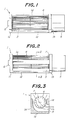
- a cross flow fan to which the present invention may be applied, and which includes an axially elongate casing 1 with a front wall 1a, a pair of side walls 1b and 1c, and a bottom and rear wall 1d of substantially L-shaped configuration. These walls 1a to 1d define a suction opening 2 in the upper portion of the casing 1, and a discharge opening 3 in the lower portion thereof.
- the impeller 4 according to the present invention is rotatably arranged inside of the casing 1, and is drivably connected at its one end to an electric motor 5 mounted on one side wall 1b while rotatably journalled on the other end by a bearing 6 secured to the other side wall 1c.
- FIG. 3 A typical flow pattern of air stream is schematically shown in Fig. 3, from which it will be seen that the cross-flow fan features a unique air stream flow indicated by thin line arrows, which is directed from the outer periphery of the impeller 4 on the side of the suction opening 2 into the inner space of the impeller 4, and further toward the outer periphery of the impeller 4 on the side of the discharge opening 3, i.e. across the impeller, as widely known in the art.
- the impeller 4 includes an integral assembly 10 formed of a plurality of axially elongate blade elements 11, and at least two disc-like holder plates 12 axially spaced from each other and integrally connected with the blade elements 11.
- Each blade element 11 has a predetermined curvature in the cross-section, and at least two cutouts (not shown) on one longitudinal edge which are axially spaced from each other by an amount corresponding to the axial distance between the holder plates 12.
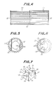
- each holder plate 12 has, for receiving the blade element 11, a plurality of slits 13 with a curvature corresponding to that of the blade element 11. These slits 13 are equidistantly or equiangularly spaced from each other and extend radially inwardly from the outer periphery of the holder plate 12.
- the slits 13 in the holder plate 12 are prepared to have an initial width over the entire length, which is greater than the thickness of the blade element 11.
- Each slit 13 has a radially inner end 14 which is much wider than the remaining portions of the slits, and widens on the concave side thereof.
- a radially outwardly protruding segmentary region 15 is defined by each neighboring pair of the slits 13, and is formed with at least one perforation 16 of suitable configuration which is located near the inner end 14 of the relevant slit 13 on convex side thereof.
- each blade element 11 is inserted into the associated slit 13 of the holder plate 12, with the above-mentioned cutout brought into engagement with the inner end 14 of the slit 13 so as to assure an accurate positioning of the blade element. Because the initial width of the slits 13 is greater than the thickness of the blade element 11, as mentioned above, the insertion of the blade elements 11 into the slits 13 does not require a delicate manipulation, and can be carried out very easily and in short a time. There is no risk of the blade elements 11 being subjected to undesired deformation during the insertion into the slits.
- the pressure P induces such a deformation of the segmentary regions 15 that each region 15 on its radially outer edge 17 is tightly urged against the opposite side wall of the neighboring region 15, with each blade element 11 being fixedly clamped by, and between, opposite side walls of the relevant slit 13.
- the deformation of the segmentary regions 15 can be carried out in a very facilitated manner, due to the presence of relatively wide inner end 14 of each slit 13 and of the perforation 16 in each segmentary region 15 near such an inner end 14, or due to a smaller effective width of each segmentary region near its radially innermost location.
- the above-mentioned deformation of the segmentary regions 15 accompanies, and is clearly recognizable by, a deformation of the perforation 16. More particularly, in case of the perforations 16 of initially circular configuration, for example, after the application of the pressure P with a resultant deforma tion of the segmentary regions 15, the perforation 16 is deformed to assume a substantially oval configuration.
- the outer periphery of the holder plate 12 may be further machined, e.g. with a grinder or the like, to obtain a smooth outer circular contour with an improved accuracy.
- a plurality of integral impeller assemblies 10a, 10b, 10c each composed of the blade elements 11 and the holder plates 12.
- continuous bodies each formed of a plurality of longitudinally aligned blade elements 11, and having a length which is several times greater than that of the blade element 11, are assembled with a 16 required number of the holder plates 12 to initially form a longitudinally aligned assemblies 10a, 10b, 10c connected with each other as an integral body, which is then cut at predetermined locations to separate the assemblies 10a, 10b, 10c from each other.
- Such a separation of the assemblies 10a, 10b, 10c can be carried out either sequentially by a single circular saw S, or simultaneously by a plurality of circular saws S, while rotating the integral body of the assemblies 10a, 10b, 10c.
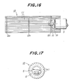
- each impeller assembly 10 which may be manufactured as above, is further provided with two shafts on both sides thereof, one shaft 18 being connected to the electric motor 5 as the drive shaft, with the other shaft (not shown) journalled by the bearing 6.
- the assembly 10 according to the embodiment illustrated therein includes three holder plates 12a, 12b and 12c of which two holder plates 12a, 12b are arranged on the axial ends of the assembly 10, while the third holder plate 12c is arranged in the axially intermediate region of the assembly 10.
- the drive shaft 18 is connected to the last-mentioned holder plate 12c in a form-locking manner.
- the drive shaft 18 has a free end portion 19 of a non-circular, substantially D-shaped cross-section, as shown in Figs. 10, 12 and 13, which is formed with a circumferential groove 20.
- the holder plate 12c to be connected with the drive shaft 18 has a boss 21 which, as shown in Fig. 11, is formed with a center bore 21a of a non-circular, substantially D-shaped cross-section corresponding to that of the free end portion 19 of the drive shaft 18.
- the boss 21 is integrally formed with resilient lugs 22a, 22b projecting radially inwardly therefrom.
- the lugs 22a, 22b are adapted to deflect axially during the insertion of the free end portion 19 into the center bore 21a of the boss 21, and to subsequently snap into the circumferential groove 20 in the free end portion 19 of the drive shaft 18, thereby to prevent unintentional withdrawal of the drive shaft 18 from the boss 21 of the holder plate 12c.
- the drive shaft 18 can be readily connected to the boss 21 of the holder plate 12c in a form-locking manner, and positively retained in place, simply by inserting the free end portion 19 into the center bore 21a of the boss 21.
- the lugs 22a, 22b projecting radially inwardly from the boss 21 deflects axially during insertion of the free end portion 19 of the drive shaft 18 into the boss 21.
- the lugs 22a, 22b subsequently snap into the circumferential groove 20 in the free end portion 19.
- the boss 21 of the holder plate 12c to be connected to the drive shaft 18 is preferably formed with three longitudinal slits 23a, 23b, 23c, and is thereby circumferentially divided into three segments 24a, 24b, 24c.
- two segments 24a, 24b define the arcuate portion of the inner contour of the center bore 21a of the D-shaped cross-section, and are provided with the above-mentioned resilient lugs 22a, 22b.
- the remaining segment 24c defining a straight portion of the inner contour of the center bore 21a of the D-shaped cross-section is not provided with the lug.
- Circumferential division of the boss 21 into three segments 24a, 24b, 24c serves to improve the flexibility of the lugs 22a, 22b in the axial direction, and to facilitate the deflection of the lugs 22a, 22b when the free end portion 19 of the drive shaft 18 is inserted into the boss 21.
- each lug 22a, 22b may each have a somewhat tapered end as shown in Fig. 15, to provide a further improved flexibility.
- each lug 22a, 22b may be arranged such that, by applying a predetermined axial force in a direction opposite to the insertion direction, they can be axially deflected and thereby disengaged from the circumferential groove 20 in the free end portion 19 of the drive shaft 18 to permit withdrawal of the drive shaft whenever necessary, while avoiding unintentional withdrawal thereof.
- the drive shaft 18 may consist of an output shaft of the electric motor 5 to eliminate provision of a separate coupling shaft.
- the arrangement may be such that one axial end of the impeller assembly 10 does not include the holder plate 12 and leaves a space circumscribed by, and radially inwardly of the blade elements 11 to open to the above-mentioned axial end, with the electric motor 5 arranged at least partly in said open space.
- the present invention may be applied to an impeller assembly including three or more holder plates, and divided into two or more longitudinally aligned sections in which the number of blade elements arranged in one section differs from that in the other section.
- the impeller assembly 10 includes three holder plates 12a, 12b, 12c, and is longitudinally divided into section A between a first pair of holder plates 12a, 12b, and section B between a second pair of holder plates 12b, 12c.
- the section A includes a predetermined number N of the blade elements 11, while the section B includes another predetermined number 2N of the blade elements 11.
- different sets of the blade elements 11 may be used, wherein each blade element 11 of the first set as shown in Fig.
- each blade element 11 of the second set as shown in Fig. 19b has a length of approximately 2L and is used for the sections A and B.
- the present invention may be applied to a cross-flow fan including two or more impeller assemblies 10a, 10b which are longitudinally aligned with each other, and adapted to be engaged with or disengaged from the other. That is, the cross-flow fan includes a first impeller assembly 10a permanently connected to the electric motor 5, and a second impeller assembly 10b which is axially slidable toward and away from the first impeller assembly 10a. When the two impeller assemblies 10a, 10b are spaced from each other, as shown in Fig. 20, only the first impeller assembly 10a is driven by the electric motor 5.
- the blade elements 11 of the two assemblies 10a, 10b are engaged with each other, as shown in Fig. 21, and function as a kind of clutch so that the second assembly 10b can also be driven by the electric motor 5.
- the above-mentioned arrangement allows a substantial space saving and serves to significantly reduce the entire cost.
- the present invention provides an improved multi-blade impeller for a cross-flow fan which is very easy to manufacture on a mass-production basis and to realize a uniform product quality. While the present invention has been described with reference to certain preferred embodiments, by way of examples only, a number of variations and/or modifications may be made without departing from the scope of the invention.
Landscapes
- Engineering & Computer Science (AREA)
- General Engineering & Computer Science (AREA)
- Mechanical Engineering (AREA)
- Structures Of Non-Positive Displacement Pumps (AREA)
Applications Claiming Priority (4)
| Application Number | Priority Date | Filing Date | Title |
|---|---|---|---|
| JP1988106991U JPH0228594U (de) | 1988-08-15 | 1988-08-15 | |
| JP106991/88U | 1988-08-15 | ||
| JP1517289A JPH02199297A (ja) | 1989-01-26 | 1989-01-26 | クロスフローフアン |
| JP15172/89 | 1989-01-26 |
Publications (2)
| Publication Number | Publication Date |
|---|---|
| EP0356314A2 true EP0356314A2 (de) | 1990-02-28 |
| EP0356314A3 EP0356314A3 (de) | 1990-05-16 |
Family
ID=26351282
Family Applications (1)
| Application Number | Title | Priority Date | Filing Date |
|---|---|---|---|
| EP89402285A Withdrawn EP0356314A3 (de) | 1988-08-15 | 1989-08-11 | Ein Mehrschaufelrad für einen Querstromlüfter |
Country Status (1)
| Country | Link |
|---|---|
| EP (1) | EP0356314A3 (de) |
Cited By (8)
| Publication number | Priority date | Publication date | Assignee | Title |
|---|---|---|---|---|
| EP0481410A3 (en) * | 1990-10-16 | 1992-05-27 | Askoll S.P.A. | Impeller to rotor coupling device |
| WO1996021538A1 (en) * | 1995-01-10 | 1996-07-18 | Nelco Manufacturing Corp. | Blast wheel having a rotatable shaft with radial discs and blades dovetailed across the discs |
| US6193467B1 (en) * | 1998-10-09 | 2001-02-27 | Delta Electronics, Inc. | Driven unit, especially for use in a cross flow fan |
| WO2011148396A1 (en) * | 2010-05-28 | 2011-12-01 | Coplast Srl | Cooling fan for a rotary machine technical field of application of the invention |
| WO2011148397A1 (en) * | 2010-05-28 | 2011-12-01 | Coplast Srl | Cooling fan for a rotary machine |
| WO2011148398A1 (en) * | 2010-05-28 | 2011-12-01 | Coplast Srl | Cooling fan for a rotary machine |
| WO2016050259A1 (en) * | 2014-09-29 | 2016-04-07 | Arcelik Anonim Sirketi | Fan assembly for cooking oven with improved energy consumption |
| CN112576523A (zh) * | 2020-12-04 | 2021-03-30 | 重庆海尔空调器有限公司 | 贯流风扇及具有其的空调 |
Family Cites Families (5)
| Publication number | Priority date | Publication date | Assignee | Title |
|---|---|---|---|---|
| DE1428061A1 (de) * | 1964-09-15 | 1969-05-14 | Fischbach Kg Blech Metall R | Anordnung an Radialgeblaesen |
| DE1503578A1 (de) * | 1966-02-21 | 1971-01-28 | Nikolaus Laing | Trommellaeufer |
| DE3206390C2 (de) * | 1982-02-22 | 1984-10-11 | Siemens AG, 1000 Berlin und 8000 München | Verdrehungs- und verschiebungssichere lösbare Verbindung der Nabe eines einstückigen Kunststoff-Lüfterrades mit einer Maschinenwelle |
| DE3223284A1 (de) * | 1982-06-22 | 1983-12-29 | Feinwerktechnik Schleicher & Co, 7778 Markdorf | Vorrichtung zur radialen und axialen verschiebungssicherung eines teils auf einer rotierenden welle |
| DE3500465A1 (de) * | 1985-01-09 | 1986-07-10 | Wella Ag, 6100 Darmstadt | Befestigung eines luefterrades auf der motorwelle eines elektromotors |
-
1989
- 1989-08-11 EP EP89402285A patent/EP0356314A3/de not_active Withdrawn
Cited By (9)
| Publication number | Priority date | Publication date | Assignee | Title |
|---|---|---|---|---|
| EP0481410A3 (en) * | 1990-10-16 | 1992-05-27 | Askoll S.P.A. | Impeller to rotor coupling device |
| WO1996021538A1 (en) * | 1995-01-10 | 1996-07-18 | Nelco Manufacturing Corp. | Blast wheel having a rotatable shaft with radial discs and blades dovetailed across the discs |
| US6193467B1 (en) * | 1998-10-09 | 2001-02-27 | Delta Electronics, Inc. | Driven unit, especially for use in a cross flow fan |
| WO2011148396A1 (en) * | 2010-05-28 | 2011-12-01 | Coplast Srl | Cooling fan for a rotary machine technical field of application of the invention |
| WO2011148397A1 (en) * | 2010-05-28 | 2011-12-01 | Coplast Srl | Cooling fan for a rotary machine |
| WO2011148398A1 (en) * | 2010-05-28 | 2011-12-01 | Coplast Srl | Cooling fan for a rotary machine |
| WO2016050259A1 (en) * | 2014-09-29 | 2016-04-07 | Arcelik Anonim Sirketi | Fan assembly for cooking oven with improved energy consumption |
| CN112576523A (zh) * | 2020-12-04 | 2021-03-30 | 重庆海尔空调器有限公司 | 贯流风扇及具有其的空调 |
| CN112576523B (zh) * | 2020-12-04 | 2023-06-02 | 重庆海尔空调器有限公司 | 贯流风扇及具有其的空调 |
Also Published As
| Publication number | Publication date |
|---|---|
| EP0356314A3 (de) | 1990-05-16 |
Similar Documents
| Publication | Publication Date | Title |
|---|---|---|
| EP0947705A2 (de) | Radiallüftergehaüse | |
| EP0356314A2 (de) | Ein Mehrschaufelrad für einen Querstromlüfter | |
| US3385511A (en) | Blower | |
| US5873164A (en) | Method for manufacturing a fan wheel | |
| SU694098A3 (ru) | Направл ющий аппарат осевого компрессора | |
| US3262637A (en) | Individual blade mountings in a blower wheel | |
| US4808090A (en) | Vacuum motor fan cover | |
| JPS6014920B2 (ja) | 送風機の羽根車 | |
| US2431647A (en) | Centrifugal fan | |
| US2470966A (en) | Rotor | |
| US5476365A (en) | Centrifugal blower wheel with forward curved multi-blades | |
| US3111173A (en) | Fan with slinger ring | |
| EP0440048A1 (de) | Lüfterrad | |
| US2021707A (en) | Fluid reaction device | |
| DE2210271B2 (de) | Radialventilator | |
| EP3592985B1 (de) | Teilesatz und verfahren für die fertigung eines radiallüfters | |
| GB2367596A (en) | Fan rotor construction | |
| JPS6318800Y2 (de) | ||
| EP0456596A1 (de) | Kreiselpumpe | |
| JPH0658290A (ja) | 横断流送風機 | |
| JPS61261699A (ja) | 送風機 | |
| EP1621775A2 (de) | Gebläserotor aus Verbundwerkstoff für Tangentialgebläse | |
| JPS62258197A (ja) | 遠心送風機 | |
| JP2951145B2 (ja) | 送風装置 | |
| JPH07127598A (ja) | 多翼送風機の羽根車の羽根 |
Legal Events
| Date | Code | Title | Description |
|---|---|---|---|
| PUAI | Public reference made under article 153(3) epc to a published international application that has entered the european phase |
Free format text: ORIGINAL CODE: 0009012 |
|
| AK | Designated contracting states |
Kind code of ref document: A2 Designated state(s): DE ES GB IT |
|
| PUAL | Search report despatched |
Free format text: ORIGINAL CODE: 0009013 |
|
| AK | Designated contracting states |
Kind code of ref document: A3 Designated state(s): DE ES GB IT |
|
| 17P | Request for examination filed |
Effective date: 19901026 |
|
| 17Q | First examination report despatched |
Effective date: 19920207 |
|
| STAA | Information on the status of an ep patent application or granted ep patent |
Free format text: STATUS: THE APPLICATION IS DEEMED TO BE WITHDRAWN |
|
| 18D | Application deemed to be withdrawn |
Effective date: 19920619 |