EP0355975A2 - Mehrfach-Rückführungs-Regelungsverfahren und -system zur Steuerung von Radschlupf - Google Patents
Mehrfach-Rückführungs-Regelungsverfahren und -system zur Steuerung von Radschlupf Download PDFInfo
- Publication number
- EP0355975A2 EP0355975A2 EP89307099A EP89307099A EP0355975A2 EP 0355975 A2 EP0355975 A2 EP 0355975A2 EP 89307099 A EP89307099 A EP 89307099A EP 89307099 A EP89307099 A EP 89307099A EP 0355975 A2 EP0355975 A2 EP 0355975A2
- Authority
- EP
- European Patent Office
- Prior art keywords
- clutch
- feedback
- engine
- feedback control
- speed
- Prior art date
- Legal status (The legal status is an assumption and is not a legal conclusion. Google has not performed a legal analysis and makes no representation as to the accuracy of the status listed.)
- Granted
Links
- 238000000034 method Methods 0.000 title claims abstract description 27
- 230000004044 response Effects 0.000 claims abstract description 36
- 230000001276 controlling effect Effects 0.000 claims abstract description 15
- 238000005259 measurement Methods 0.000 claims abstract description 13
- 238000002485 combustion reaction Methods 0.000 claims abstract description 11
- 230000001105 regulatory effect Effects 0.000 claims abstract description 11
- 239000000446 fuel Substances 0.000 claims description 16
- 239000012530 fluid Substances 0.000 claims description 5
- 230000033228 biological regulation Effects 0.000 claims description 2
- 230000008901 benefit Effects 0.000 description 15
- 238000013459 approach Methods 0.000 description 8
- 230000005540 biological transmission Effects 0.000 description 7
- 101000802640 Homo sapiens Lactosylceramide 4-alpha-galactosyltransferase Proteins 0.000 description 5
- 102100035838 Lactosylceramide 4-alpha-galactosyltransferase Human genes 0.000 description 5
- 230000003111 delayed effect Effects 0.000 description 4
- 230000001052 transient effect Effects 0.000 description 4
- 230000001133 acceleration Effects 0.000 description 3
- 230000009471 action Effects 0.000 description 2
- 230000008878 coupling Effects 0.000 description 2
- 238000010168 coupling process Methods 0.000 description 2
- 238000005859 coupling reaction Methods 0.000 description 2
- 238000001514 detection method Methods 0.000 description 2
- 238000010586 diagram Methods 0.000 description 2
- 230000006835 compression Effects 0.000 description 1
- 238000007906 compression Methods 0.000 description 1
- 230000007423 decrease Effects 0.000 description 1
- 230000000694 effects Effects 0.000 description 1
- 230000006698 induction Effects 0.000 description 1
- 230000003993 interaction Effects 0.000 description 1
- 239000000203 mixture Substances 0.000 description 1
- 230000002265 prevention Effects 0.000 description 1
- 238000005070 sampling Methods 0.000 description 1
Images


Classifications
-
- B—PERFORMING OPERATIONS; TRANSPORTING
- B60—VEHICLES IN GENERAL
- B60W—CONJOINT CONTROL OF VEHICLE SUB-UNITS OF DIFFERENT TYPE OR DIFFERENT FUNCTION; CONTROL SYSTEMS SPECIALLY ADAPTED FOR HYBRID VEHICLES; ROAD VEHICLE DRIVE CONTROL SYSTEMS FOR PURPOSES NOT RELATED TO THE CONTROL OF A PARTICULAR SUB-UNIT
- B60W10/00—Conjoint control of vehicle sub-units of different type or different function
- B60W10/04—Conjoint control of vehicle sub-units of different type or different function including control of propulsion units
- B60W10/06—Conjoint control of vehicle sub-units of different type or different function including control of propulsion units including control of combustion engines
-
- B—PERFORMING OPERATIONS; TRANSPORTING
- B60—VEHICLES IN GENERAL
- B60K—ARRANGEMENT OR MOUNTING OF PROPULSION UNITS OR OF TRANSMISSIONS IN VEHICLES; ARRANGEMENT OR MOUNTING OF PLURAL DIVERSE PRIME-MOVERS IN VEHICLES; AUXILIARY DRIVES FOR VEHICLES; INSTRUMENTATION OR DASHBOARDS FOR VEHICLES; ARRANGEMENTS IN CONNECTION WITH COOLING, AIR INTAKE, GAS EXHAUST OR FUEL SUPPLY OF PROPULSION UNITS IN VEHICLES
- B60K28/00—Safety devices for propulsion-unit control, specially adapted for, or arranged in, vehicles, e.g. preventing fuel supply or ignition in the event of potentially dangerous conditions
- B60K28/10—Safety devices for propulsion-unit control, specially adapted for, or arranged in, vehicles, e.g. preventing fuel supply or ignition in the event of potentially dangerous conditions responsive to conditions relating to the vehicle
- B60K28/16—Safety devices for propulsion-unit control, specially adapted for, or arranged in, vehicles, e.g. preventing fuel supply or ignition in the event of potentially dangerous conditions responsive to conditions relating to the vehicle responsive to, or preventing, spinning or skidding of wheels
- B60K28/165—Safety devices for propulsion-unit control, specially adapted for, or arranged in, vehicles, e.g. preventing fuel supply or ignition in the event of potentially dangerous conditions responsive to conditions relating to the vehicle responsive to, or preventing, spinning or skidding of wheels acting on elements of the vehicle drive train other than the propulsion unit and brakes, e.g. transmission, clutch, differential
-
- B—PERFORMING OPERATIONS; TRANSPORTING
- B60—VEHICLES IN GENERAL
- B60W—CONJOINT CONTROL OF VEHICLE SUB-UNITS OF DIFFERENT TYPE OR DIFFERENT FUNCTION; CONTROL SYSTEMS SPECIALLY ADAPTED FOR HYBRID VEHICLES; ROAD VEHICLE DRIVE CONTROL SYSTEMS FOR PURPOSES NOT RELATED TO THE CONTROL OF A PARTICULAR SUB-UNIT
- B60W10/00—Conjoint control of vehicle sub-units of different type or different function
- B60W10/02—Conjoint control of vehicle sub-units of different type or different function including control of driveline clutches
-
- B—PERFORMING OPERATIONS; TRANSPORTING
- B60—VEHICLES IN GENERAL
- B60W—CONJOINT CONTROL OF VEHICLE SUB-UNITS OF DIFFERENT TYPE OR DIFFERENT FUNCTION; CONTROL SYSTEMS SPECIALLY ADAPTED FOR HYBRID VEHICLES; ROAD VEHICLE DRIVE CONTROL SYSTEMS FOR PURPOSES NOT RELATED TO THE CONTROL OF A PARTICULAR SUB-UNIT
- B60W10/00—Conjoint control of vehicle sub-units of different type or different function
- B60W10/04—Conjoint control of vehicle sub-units of different type or different function including control of propulsion units
-
- B—PERFORMING OPERATIONS; TRANSPORTING
- B60—VEHICLES IN GENERAL
- B60W—CONJOINT CONTROL OF VEHICLE SUB-UNITS OF DIFFERENT TYPE OR DIFFERENT FUNCTION; CONTROL SYSTEMS SPECIALLY ADAPTED FOR HYBRID VEHICLES; ROAD VEHICLE DRIVE CONTROL SYSTEMS FOR PURPOSES NOT RELATED TO THE CONTROL OF A PARTICULAR SUB-UNIT
- B60W30/00—Purposes of road vehicle drive control systems not related to the control of a particular sub-unit, e.g. of systems using conjoint control of vehicle sub-units
- B60W30/18—Propelling the vehicle
- B60W30/1819—Propulsion control with control means using analogue circuits, relays or mechanical links
-
- B—PERFORMING OPERATIONS; TRANSPORTING
- B60—VEHICLES IN GENERAL
- B60W—CONJOINT CONTROL OF VEHICLE SUB-UNITS OF DIFFERENT TYPE OR DIFFERENT FUNCTION; CONTROL SYSTEMS SPECIALLY ADAPTED FOR HYBRID VEHICLES; ROAD VEHICLE DRIVE CONTROL SYSTEMS FOR PURPOSES NOT RELATED TO THE CONTROL OF A PARTICULAR SUB-UNIT
- B60W50/00—Details of control systems for road vehicle drive control not related to the control of a particular sub-unit, e.g. process diagnostic or vehicle driver interfaces
- B60W2050/0001—Details of the control system
- B60W2050/0002—Automatic control, details of type of controller or control system architecture
- B60W2050/0008—Feedback, closed loop systems or details of feedback error signal
- B60W2050/0009—Proportional differential [PD] controller
-
- B—PERFORMING OPERATIONS; TRANSPORTING
- B60—VEHICLES IN GENERAL
- B60W—CONJOINT CONTROL OF VEHICLE SUB-UNITS OF DIFFERENT TYPE OR DIFFERENT FUNCTION; CONTROL SYSTEMS SPECIALLY ADAPTED FOR HYBRID VEHICLES; ROAD VEHICLE DRIVE CONTROL SYSTEMS FOR PURPOSES NOT RELATED TO THE CONTROL OF A PARTICULAR SUB-UNIT
- B60W50/00—Details of control systems for road vehicle drive control not related to the control of a particular sub-unit, e.g. process diagnostic or vehicle driver interfaces
- B60W2050/0001—Details of the control system
- B60W2050/0002—Automatic control, details of type of controller or control system architecture
- B60W2050/0008—Feedback, closed loop systems or details of feedback error signal
- B60W2050/001—Proportional integral [PI] controller
-
- B—PERFORMING OPERATIONS; TRANSPORTING
- B60—VEHICLES IN GENERAL
- B60W—CONJOINT CONTROL OF VEHICLE SUB-UNITS OF DIFFERENT TYPE OR DIFFERENT FUNCTION; CONTROL SYSTEMS SPECIALLY ADAPTED FOR HYBRID VEHICLES; ROAD VEHICLE DRIVE CONTROL SYSTEMS FOR PURPOSES NOT RELATED TO THE CONTROL OF A PARTICULAR SUB-UNIT
- B60W50/00—Details of control systems for road vehicle drive control not related to the control of a particular sub-unit, e.g. process diagnostic or vehicle driver interfaces
- B60W2050/0001—Details of the control system
- B60W2050/0019—Control system elements or transfer functions
- B60W2050/0022—Gains, weighting coefficients or weighting functions
-
- B—PERFORMING OPERATIONS; TRANSPORTING
- B60—VEHICLES IN GENERAL
- B60W—CONJOINT CONTROL OF VEHICLE SUB-UNITS OF DIFFERENT TYPE OR DIFFERENT FUNCTION; CONTROL SYSTEMS SPECIALLY ADAPTED FOR HYBRID VEHICLES; ROAD VEHICLE DRIVE CONTROL SYSTEMS FOR PURPOSES NOT RELATED TO THE CONTROL OF A PARTICULAR SUB-UNIT
- B60W2510/00—Input parameters relating to a particular sub-units
- B60W2510/06—Combustion engines, Gas turbines
- B60W2510/0671—Engine manifold pressure
-
- B—PERFORMING OPERATIONS; TRANSPORTING
- B60—VEHICLES IN GENERAL
- B60W—CONJOINT CONTROL OF VEHICLE SUB-UNITS OF DIFFERENT TYPE OR DIFFERENT FUNCTION; CONTROL SYSTEMS SPECIALLY ADAPTED FOR HYBRID VEHICLES; ROAD VEHICLE DRIVE CONTROL SYSTEMS FOR PURPOSES NOT RELATED TO THE CONTROL OF A PARTICULAR SUB-UNIT
- B60W2710/00—Output or target parameters relating to a particular sub-units
- B60W2710/06—Combustion engines, Gas turbines
- B60W2710/0605—Throttle position
-
- B—PERFORMING OPERATIONS; TRANSPORTING
- B60—VEHICLES IN GENERAL
- B60W—CONJOINT CONTROL OF VEHICLE SUB-UNITS OF DIFFERENT TYPE OR DIFFERENT FUNCTION; CONTROL SYSTEMS SPECIALLY ADAPTED FOR HYBRID VEHICLES; ROAD VEHICLE DRIVE CONTROL SYSTEMS FOR PURPOSES NOT RELATED TO THE CONTROL OF A PARTICULAR SUB-UNIT
- B60W2710/00—Output or target parameters relating to a particular sub-units
- B60W2710/06—Combustion engines, Gas turbines
- B60W2710/0616—Position of fuel or air injector
-
- B—PERFORMING OPERATIONS; TRANSPORTING
- B60—VEHICLES IN GENERAL
- B60W—CONJOINT CONTROL OF VEHICLE SUB-UNITS OF DIFFERENT TYPE OR DIFFERENT FUNCTION; CONTROL SYSTEMS SPECIALLY ADAPTED FOR HYBRID VEHICLES; ROAD VEHICLE DRIVE CONTROL SYSTEMS FOR PURPOSES NOT RELATED TO THE CONTROL OF A PARTICULAR SUB-UNIT
- B60W2710/00—Output or target parameters relating to a particular sub-units
- B60W2710/06—Combustion engines, Gas turbines
- B60W2710/0666—Engine torque
Definitions
- the invention relates to a method and system for controlling the wheel slip of a driven wheel coupled to an internal combustion engine.
- German patents 2058819 and 2832739 wherein the engine throttle is controlled in inverse relation to a measured difference in rotation between a driven wheel and a non-driven wheel.
- U.S. patent No. 4,554,990 issued to Kamiya et al discloses a control system wherein the difference in rotation between a driven wheel and a non-driven wheel is used as a feedback variable.
- the other feedback variables are a signal related to actual throttle position, and a signal related to throttle position commanded by a vehicle operator.
- the inventors herein have recognised numerous disadvantages of these prior approaches.
- One disadvantage is that torque is removed from the drive wheel by controlling an engine input (throttle). Thus, torque is not removed from the drive wheel until after time delay through the engine is incurred.
- Another disadvantage is that the feedback variable for engine torque output is derived from wheel speed. This feedback variable is therefore delayed by a time delay through the engine and drivetrain resulting in a feedback loop with poor transient response time.
- An object of the present invention is to provide both a feedback control system and method to control wheel slip with a faster and more stable transient response time than heretofore possible.
- a method comprises the steps of: generating a first feedback variable related to the wheel slip; generating a second feedback variable related to hydraulic pressure applied to the clutch; summing said first and second feedback variables to generate a feedback control signal; and regulating the hydraulic pressure applied to the clutch in response to the feedback control signal to reduce the wheel slip.
- An advantage of the above method is that torque is removed from the driven wheel without incurring the time delay through the engine inherent in prior approaches. A faster response time is thereby achieved than heretofore possible.
- a feedback control method for controlling the wheel slip of a wheel driven by torque coupled through an electronically controlled hydraulically operable clutch from an internal combustion engine. More specifically, the feedback control method comprises the steps of: measuring the driven wheel speed; generating a first feedback variable in response to the driven wheel speed which is related to the wheel slip; generating a second feedback variable related to hydraulic pressure applied to the clutch; summing said first and second feedback variables to generate a feedback control signal; slipping the clutch by regulating the hydraulic pressure applied to the clutch in response to the feedback control signal to reduce the driven wheel speed; and adjusting engine speed in response to the measurement of driven wheel speed to prevent over-revving of the engine and maintain a desired predetermined positive torque on the driven wheel while the clutch is being slipped during the regulation step.
- An advantage of this particular aspect of the invention is that the engine is prevented from over revving which would otherwise occur when the clutch is slipped in response to a detection of wheel slip.
- a further advantage is that a desired predetermined positive torque is maintained on the driven wheel while the engine speed is being downwardly adjusted thereby preventing clutch lock-up and associated drivability problems.
- a feedback control method for controlling the wheel slip of a wheel driven by torque coupled through an electronically controlled hydraulically operable clutch from an internal combustion engine having an intake manifold for inducting air therethrough. More specifically, the feedback control method comprises the steps of: measuring driven wheel speed; generating a first feedback variable in response to the measurement of driven wheel speed which is related to the wheel slip; generating a second feedback variable related to hydraulic pressure applied to the clutch; summing the first and second feedback variables to generate a first feedback control signal; slipping the clutch by regulating the hydraulic pressure applied to the clutch in response to the first feedback control signal to reduce the driven wheel speed; generating a third feedback variable indicative of desired engine speed by calculating an engine speed proportional to the measurement of driven wheel speed and adding a preselected speed offset to provide a desired predetermined positive torque on the driven wheel; generating a fourth feedback variable indicative of engine torque output by measuring pressure in the intake manifold; summing the third and fourth feedback variables to generate a second feedback control signal; and adjusting the
- An advantage of this aspect of the invention is that a feedback variable related to engine torque output is derived from an engine input parameter (manifold pressure) thereby resulting in faster feedback control than heretofore possible.
- prior approaches relied on a measurement of wheel slip to provide a feedback variable indicative of engine torque output thereby incurring the time delay through the engine, drive train, and wheel.
- the aspect of the invention described hereinabove utilises intake manifold pressure as a feedback variable indicative of engine torque output thereby avoiding the time delay indicative of prior approaches.
- a further advantage is that the engine is prevented from over-revving while the clutch is slipped while maintaining a desired predetermined positive torque on the driven wheel thereby preventing clutch lock-up.
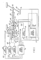
- clutch feedback controller 12 and engine feedback controller 14 are shown as feedback control systems receiving inputs from, and controlling, motor vehicle 16 when detected wheel slip exceeds a desired or preselected value.
- Motor vehicle 16 is shown in this particular example having an internal combustion engine 18 coupled to drive wheel 20 via clutch 22, automatic transmission 26, driveshaft 28, and differential/axle 32.
- clutch 22 is an electronically controlled, hydraulically actuated clutch coupled directly between engine 18 and transmission 26 without the need for a conventional torque converter.
- Engine 18 is shown in this example including an intake manifold 36 for inducting an air/fuel mixture therein via air/fuel intake 38.
- Fuel injector 40 shown as a portion of a central fuel injected system in this example, injects fuel into air/fuel intake 38 under control of conventional fuel controller 42.
- Throttle plate 46 is here shown actuated by servo motor 48 in response to throttle controller 50 for adjusting flow through air/fuel intake 38 in a conventional manner.
- Conventional ignition controller 54 is shown providing ignition timing and appropriate ignition spark to spark plugs 56, 58, 60, and 62.
- the feedback control systems described herein may be used to advantage with any type of combustion engine such as, for example, carburetted engines, multiport fuel injected engines, and direct fuel injected engines. Further, the feedback control systems are not limited to automobiles, but may be used to advantage with any apparatus having an engine coupled to a drive wheel through a clutch such as, for example, a motor-cycle.
- clutch 22 is shown including clutch plates 64 coupled to transmission shaft 68, and friction elements 65 operably coupled to engine shaft 66 via clutch housing 76.
- Hydraulic piston 70 is shown coupled to friction elements 65 for coupling and decoupling clutch plates 64 to friction elements 65 thereby coupling and decoupling engine 18 to transmission 26.
- Pressurised hydraulic fluid from a transmission pump enters hydraulic piston 70 under control of electronically controlled solenoid valve 72.
- Microprocessor or clutch controller 74 electronically actuates solenoid valve 72 by pulse width modulated signal CPW to control clutch 22. The amount of torque coupled from engine 18 to transmission 26 is controlled by slippage of clutch 22.
- the slippage of clutch 22 is inversely related to the hydraulic pressure applied by hydraulic piston 70 and therefore inversely related to the pulse width of signal CPW.
- Pressure transducer 78 provides electronic signal P proportional to the hydraulic pressure applied by hydraulic piston 70. As described in greater detail hereinafter, pressure signal P is a feedback variable to clutch feedback controller 12.
- Clutch 22 and associated controls are shown and described in more detail in U.S. patent No. 4,487,303 issued to Boueri et al and assigned to Ford Motor Company, the specification of which is incorporated herein by reference.
- feedback clutch controller 12 is shown schematically as a flow chart of computational and decision making steps represented as blocks. Each block shown herein describes an operation performed by the controller. It is noted that these operations may also be performed by discrete components wherein each block comprises an array of circuits such as, for example, IC adders and IC multipliers.
- Error signal E(k) is multiplied by gain constant G1 in block 90 once each sample period to generate feedback variable G1*E(k) related to wheel slip.
- the derivative of V D may be calculated to provide a measurement of abrupt acceleration associated with wheel slip thereby avoiding the need for a non-driven wheel sensor. This scheme may be used to particular advantage with four-wheel drive vehicles.
- wheel slip may be determined by comparing the driven wheel speed to actual vehicle speed. A measurement of actual wheel speed may be obtained from a radar unit such as Doppler Radar Unit II, sold by Dickie-John Corporation of Auburn, Illinois.
- pressure signal P is sampled and multiplied once each sample period by gain constant G2 to generate feedback variable G2*P(k) related to clutch pressure.
- Sampled pressure signal P(k) is also shown delayed in block 94 and then multiplied by gain constant G3 in block 96 to form feedback variable G3*P(k-1) which is a higher order feedback variable related to clutch pressure.
- clutch controller 12 proportionally reduces the pulse width of signal CPW applied to solenoid valve 72. Accordingly, clutch 22 is slipped in proportion to the absolute magnitude of feedback control signal DC(k) thereby proportionally reducing torque coupled through clutch 22 and applied against driven wheel 20.
- feedback control signal DC(k) may include other feedback variables derived from error signal E(k).
- E(k) a derivative of E(k) or an integral of E(k) or a combination of both may be used to advantage.
- clutch feedback controller 12 Operation of clutch feedback controller 12 and its effect on wheel slip and engine speed are shown schematically in Figures 4A through 4C.
- Figure 4A an illustrative example is presented wherein motor vehicle 16 encounters a slippery surface while accelerating.
- driven wheel speed V D is shown abruptly accelerating as driven wheel 20 begins to slip beyond desired wheel slippage.
- feedback clutch controller 12 appropriately slips clutch 22 thereby reducing torque coupled therethrough as illustrated at time t2 with reference Figure 4B. Acceleration of driven wheel 20 (slope of V D versus time graph shown in Figure 4A) therefore decreases after time t2.
- Engine feedback controller 14 is now described with particular reference to the electrical schematic shown in Figure 3.
- the blocks shown therein are representative of computational and decision making steps performed by a controller in this example. Those skilled in the art will recognise that these blocks may also represent an array of conventional discrete components such as IC multipliers and IC adders. It will also be recognised that although three feedback control signals are generated for separately controlling engine spark [SA(k)], engine fuel [pw(k)], and engine throttle [TA(k)], the invention may be used to advantage with any one of any combination of these or other control signals controlling engine operation.
- N ed V D *SR+S cs .
- a desired predetermined torque is coupled from engine 18 to clutch 22 which is positive with respect to torque coupled thereto from driven wheel 20. Accordingly, when engine feedback controller 14 reduces engine speed to prevent flare-up, engine speed is not reduced below N ed by action of feedback engine controller 14. If engine speed were reduced below N ed , engine torque applied to clutch 22 may result in clutch lock-up, or sticking, and associated drivability problems.
- actual engine speed signal N e and desired engine speed signal N ed are sampled and their difference multiplied by gain constant G4 once each sample period.
- Feedback variable G4*[N e (k)-N ed (k)] is thereby generated for summation in summation block 114 of feedback engine controller 14.
- intake manifold pressure signal MAP (appropriately biased) is shown sampled and multiplied by gain constant G5 once each sample period to generate feedback variable G5*MAP(k) for summation in summation block 114.
- Sampled signal MAP(k) is also delayed in delay block 116 by a predetermined number of sample periods (n) to generate signal MAP(k-n) related to the torque output of engine 18. More specifically, the delay is approximately equal to an integer number of time intervals between the induction stroke and the compression stroke. This time delay is derived from a crank angle signal CA which is related to the crank angle of engine 18.
- MAP(k-n) the delayed measurement of absolute manifold pressure, MAP(k-n) is proportional to torque output of engine 18 at the time that torque output is generated.
- Signal MAP(k-n) is then multiplied once each sample period by gain constant G6, as shown in block 118, to generate feedback variable G6*MAP(k-n) for summation in summation block 114.
- SA(k) -G4*[N e (k)-N ed (k)] -G5*MAP(k)-G6*MAP(k-n).
- TA(k) -G10[N e (k)-N ed (k)]-G11*MAP(k)-G12*MAP(k-n).
- engine ignition controller 54 In response to feedback control signal SA(k), engine ignition controller 54 ( Figure 1) retards normal engine spark to reduce the torque output and speed of engine 18. Similarly, fuel controller 42 reduces the fuel supplied by fuel injector 40 thereby reducing engine torque output in response to feedback control signal pw(k). Engine torque output is also controlled by throttle controller 50 in response to feedback control signal TA(k) and appropriate manipulation of throttle plate 46 via servo motor 48.
- engine feedback controller 14 may be used to advantage with any one, or any combination, of the feedback control variables.
- all three feedback control variables [SA(k), TA(k), and pw(k)] are shown for a more robust feedback control system.
- engine feedback controller 14 may operate to advantage without the MAP(k) and MAP(k-n) feedback variables.
- reliance only on feedback variables derived from N ed (k) would result in slower transient response time because control of engine operation in response to variations of input conditions would be detected after a time delay through engine 18.
- feedback variables derived from MAP an indication of engine torque output is achieved by measuring MAP at the engine input thereby eliminating the time delay through engine 18.
- clutch feedback controller 12 may be used to achieve more robust feedback control and better interaction between clutch feedback controller 12 and engine feedback controller 14 by using engine feedback variables with clutch feedback controller 12 and clutch feedback variables with engine feedback controller 14.
- engine feedback variables MAP, N e and N ed are shown coupled to clutch feedback controller 12
- clutch variable P is shown coupled to engine feedback controller 14.
Landscapes
- Engineering & Computer Science (AREA)
- Chemical & Material Sciences (AREA)
- Combustion & Propulsion (AREA)
- Transportation (AREA)
- Mechanical Engineering (AREA)
- Automation & Control Theory (AREA)
- Hydraulic Clutches, Magnetic Clutches, Fluid Clutches, And Fluid Joints (AREA)
- Control Of Vehicle Engines Or Engines For Specific Uses (AREA)
Applications Claiming Priority (2)
| Application Number | Priority Date | Filing Date | Title |
|---|---|---|---|
| US233084 | 1988-08-17 | ||
| US07/233,084 US4936405A (en) | 1988-08-17 | 1988-08-17 | Multiple feedback loop control method and system for controlling wheel slip |
Publications (3)
| Publication Number | Publication Date |
|---|---|
| EP0355975A2 true EP0355975A2 (de) | 1990-02-28 |
| EP0355975A3 EP0355975A3 (de) | 1991-06-05 |
| EP0355975B1 EP0355975B1 (de) | 1994-09-28 |
Family
ID=22875825
Family Applications (1)
| Application Number | Title | Priority Date | Filing Date |
|---|---|---|---|
| EP89307099A Expired - Lifetime EP0355975B1 (de) | 1988-08-17 | 1989-07-13 | Mehrfach-Rückführungs-Regelungsverfahren und -system zur Steuerung von Radschlupf |
Country Status (3)
| Country | Link |
|---|---|
| US (1) | US4936405A (de) |
| EP (1) | EP0355975B1 (de) |
| DE (1) | DE68918537T2 (de) |
Cited By (6)
| Publication number | Priority date | Publication date | Assignee | Title |
|---|---|---|---|---|
| AU640425B2 (en) * | 1989-11-17 | 1993-08-26 | Kabushiki Kaisha Komatsu Seisakusho | Method and system of preventing wheel loader from slipping |
| EP0628442A1 (de) * | 1993-05-17 | 1994-12-14 | FICHTEL & SACHS AG | Anordnung zur Betätigung einer Reibungskupplung eines Kraftfahrzeugs |
| EP0668184A2 (de) * | 1994-02-17 | 1995-08-23 | Honda Giken Kogyo Kabushiki Kaisha | Kupplungssteuerungsvorrichtung |
| EP0835782A2 (de) * | 1996-10-10 | 1998-04-15 | Volkswagen Aktiengesellschaft | Verfahren und Vorrichtung zur Verhinderung von Momentenüberlast in einer Fahrzeugantriebseinrichtung |
| WO1999009332A1 (de) * | 1997-08-16 | 1999-02-25 | Daimlerchrysler Ag | Automatische steuerung einer kupplung |
| EP1327551A2 (de) * | 2002-01-09 | 2003-07-16 | Toyota Jidosha Kabushiki Kaisha | Fahrzeugsteuervorrichtung und Fahrzeugsteuerverfahren |
Families Citing this family (14)
| Publication number | Priority date | Publication date | Assignee | Title |
|---|---|---|---|---|
| KR970003157B1 (ko) * | 1988-12-06 | 1997-03-14 | 로베르트 보쉬 게엠베하 | 기판 토오크 제어 방법 및 장치 |
| US5527238A (en) * | 1995-04-10 | 1996-06-18 | Ford Motor Company | Automatic transmission bypass clutch slip control using nonlinear nverse dynamics |
| US6165104A (en) | 1995-12-29 | 2000-12-26 | Robert Bosch Gmbh | System for controlling a clutch and/or a motor of a vehicle |
| US6405844B1 (en) * | 1999-09-10 | 2002-06-18 | Komatsu Ltd. | Working vehicle |
| JP3555518B2 (ja) * | 1999-09-16 | 2004-08-18 | 株式会社村田製作所 | 電位センサおよびそれを用いた電子機器 |
| US7395891B2 (en) * | 2005-08-17 | 2008-07-08 | Ford Global Technologies, Llc | Engine torque truncation method for a four-wheel drive vehicle |
| US9126480B2 (en) | 2008-12-22 | 2015-09-08 | Caterpillar Inc. | Machine control system utilizing inertial yaw sensor |
| US8771140B2 (en) | 2008-12-22 | 2014-07-08 | Caterpillar Inc. | Machine control system utilizing inertial yaw sensor |
| US9086104B2 (en) | 2008-12-22 | 2015-07-21 | Caterpillar Inc. | System and method for controlling wheel spin and wheel slip on a machine having differentially driven wheels |
| US9296295B2 (en) | 2008-12-22 | 2016-03-29 | Caterpillar Inc. | Machine control system utilizing inertial yaw sensor |
| JP5779325B2 (ja) * | 2010-07-21 | 2015-09-16 | 川崎重工業株式会社 | 車両用減速制御装置 |
| JP5273121B2 (ja) * | 2010-10-19 | 2013-08-28 | 株式会社デンソー | 発進支援装置 |
| US9139088B2 (en) * | 2013-08-30 | 2015-09-22 | Ford Global Technologies, Llc | System and method for hybrid vehicle control during wheel slip events to limit generator speed |
| US11866117B2 (en) | 2019-01-16 | 2024-01-09 | Livewire Ev, Llc | Motorcycle with virtual braking and virtual clutch |
Citations (3)
| Publication number | Priority date | Publication date | Assignee | Title |
|---|---|---|---|---|
| GB2178871A (en) * | 1985-08-07 | 1987-02-18 | Sachs Systemtechnik Gmbh | Regulating the drive slip of a motor vehicle |
| GB2190158A (en) * | 1986-05-09 | 1987-11-11 | Teves Gmbh Alfred | Traction slip control apparatus for an automotive vehicle |
| EP0275463A2 (de) * | 1987-01-20 | 1988-07-27 | Ford-Werke Aktiengesellschaft | Rutschregelung für eine Getriebekupplung |
Family Cites Families (5)
| Publication number | Priority date | Publication date | Assignee | Title |
|---|---|---|---|---|
| DE2058819A1 (de) * | 1970-11-30 | 1972-05-31 | Egbert Hoepker Jun | Verfahren zur Drehmomentanpassung |
| DE2832739A1 (de) * | 1978-07-26 | 1980-02-07 | Volkswagenwerk Ag | Verfahren und vorrichtung zur beseitigung des durchdrehens der antriebsraeder eines kraftfahrzeuges mit verbrennungsmotor |
| US4554990A (en) * | 1982-10-12 | 1985-11-26 | Honda Giken Kogyo Kabushiki Kaisha | Anti-slip system for wheeled vehicle |
| US4487303A (en) * | 1982-12-27 | 1984-12-11 | Ford Motor Company | Automatic transmission start-up clutch control system |
| JPH0819981B2 (ja) * | 1986-02-07 | 1996-03-04 | マツダ株式会社 | 車両の伝達トルク制御装置 |
-
1988
- 1988-08-17 US US07/233,084 patent/US4936405A/en not_active Expired - Lifetime
-
1989
- 1989-07-13 DE DE68918537T patent/DE68918537T2/de not_active Expired - Fee Related
- 1989-07-13 EP EP89307099A patent/EP0355975B1/de not_active Expired - Lifetime
Patent Citations (3)
| Publication number | Priority date | Publication date | Assignee | Title |
|---|---|---|---|---|
| GB2178871A (en) * | 1985-08-07 | 1987-02-18 | Sachs Systemtechnik Gmbh | Regulating the drive slip of a motor vehicle |
| GB2190158A (en) * | 1986-05-09 | 1987-11-11 | Teves Gmbh Alfred | Traction slip control apparatus for an automotive vehicle |
| EP0275463A2 (de) * | 1987-01-20 | 1988-07-27 | Ford-Werke Aktiengesellschaft | Rutschregelung für eine Getriebekupplung |
Non-Patent Citations (1)
| Title |
|---|
| PATENT ABSTRACTS OF JAPAN vol. 9, no. 73 (M-368)(1796) 03 April 1985, & JP-A-59 202963 (NEC HOME ELECTRONICS) 16 November 1984, * |
Cited By (9)
| Publication number | Priority date | Publication date | Assignee | Title |
|---|---|---|---|---|
| AU640425B2 (en) * | 1989-11-17 | 1993-08-26 | Kabushiki Kaisha Komatsu Seisakusho | Method and system of preventing wheel loader from slipping |
| EP0628442A1 (de) * | 1993-05-17 | 1994-12-14 | FICHTEL & SACHS AG | Anordnung zur Betätigung einer Reibungskupplung eines Kraftfahrzeugs |
| EP0668184A2 (de) * | 1994-02-17 | 1995-08-23 | Honda Giken Kogyo Kabushiki Kaisha | Kupplungssteuerungsvorrichtung |
| EP0668184A3 (de) * | 1994-02-17 | 1997-06-04 | Honda Motor Co Ltd | Kupplungssteuerungsvorrichtung. |
| EP0835782A2 (de) * | 1996-10-10 | 1998-04-15 | Volkswagen Aktiengesellschaft | Verfahren und Vorrichtung zur Verhinderung von Momentenüberlast in einer Fahrzeugantriebseinrichtung |
| EP0835782A3 (de) * | 1996-10-10 | 1999-03-10 | Volkswagen Aktiengesellschaft | Verfahren und Vorrichtung zur Verhinderung von Momentenüberlast in einer Fahrzeugantriebseinrichtung |
| WO1999009332A1 (de) * | 1997-08-16 | 1999-02-25 | Daimlerchrysler Ag | Automatische steuerung einer kupplung |
| EP1327551A2 (de) * | 2002-01-09 | 2003-07-16 | Toyota Jidosha Kabushiki Kaisha | Fahrzeugsteuervorrichtung und Fahrzeugsteuerverfahren |
| EP1327551A3 (de) * | 2002-01-09 | 2006-01-18 | Toyota Jidosha Kabushiki Kaisha | Fahrzeugsteuervorrichtung und Fahrzeugsteuerverfahren |
Also Published As
| Publication number | Publication date |
|---|---|
| EP0355975A3 (de) | 1991-06-05 |
| DE68918537D1 (de) | 1994-11-03 |
| US4936405A (en) | 1990-06-26 |
| EP0355975B1 (de) | 1994-09-28 |
| DE68918537T2 (de) | 1995-01-26 |
Similar Documents
| Publication | Publication Date | Title |
|---|---|---|
| EP0355975B1 (de) | Mehrfach-Rückführungs-Regelungsverfahren und -system zur Steuerung von Radschlupf | |
| US5517414A (en) | Traction control system with active suspension | |
| US5132906A (en) | Road surface friction and hill slope estimator | |
| EP0310270B1 (de) | Verfahren und System zur Steuerung des Radschlupfes eines Fahrzeugs | |
| US5303794A (en) | Wheel spin control using electronically controlled clutches and engine controls | |
| EP0038113B1 (de) | Kupplungssteueranlage | |
| US5033573A (en) | Wheel slip control utilizing active suspension | |
| US5043896A (en) | Vehicle braking system controller/road friction and hill slope tracking system | |
| US5020622A (en) | Multiple feedback loop control method and system for controlling wheel slip | |
| US5278761A (en) | Method for vehicular wheel spin control that adapts to different road traction characteristics | |
| DE19652244B4 (de) | Verfahren zur Adaption des Greifpunktes eines Kupplungsystems | |
| JP2750071B2 (ja) | 可変動力ドライブトレインエンジン制御方法及びシステム | |
| EP0186122A1 (de) | Antriebsschlupf-Regeleinrichtung | |
| US5159990A (en) | Wheel slippage control apparatus in motor vehicle | |
| US4856610A (en) | System for controlling at least one variable influencing the drive torque of an internal combustion engine of a motor vehicle | |
| EP0531552B1 (de) | Steuergerät für einen verbrennungsmotor und ein stufenloses getriebe | |
| US5033002A (en) | Vehicle traction controller/road friction and hill slope tracking system | |
| DE19518813C1 (de) | Verfahren und Vorrichtung zur Steuerung des Drehmoments einer Brennkraftmaschine | |
| US5346032A (en) | Torque distribution control system for four wheel drive vehicle | |
| US4911259A (en) | Running control method and running control system | |
| US4623052A (en) | Method and apparatus for controlling an electromagnetic clutch for use on a vehicle | |
| EP0906199B1 (de) | Adaptives-steuerungsverfahren eines kupplungssystems | |
| DE69300139T2 (de) | Vorrichtung für die Antriebsregelung eines Kraftfahrzeugs mit einem automatischen Getriebe. | |
| DE69315508T2 (de) | Vorrichtung zur Antriebsregelung für ein Kraftfahrzeug | |
| US5682316A (en) | Vehicle traction controller with engine and brake control |
Legal Events
| Date | Code | Title | Description |
|---|---|---|---|
| PUAI | Public reference made under article 153(3) epc to a published international application that has entered the european phase |
Free format text: ORIGINAL CODE: 0009012 |
|
| AK | Designated contracting states |
Kind code of ref document: A2 Designated state(s): DE FR GB |
|
| PUAL | Search report despatched |
Free format text: ORIGINAL CODE: 0009013 |
|
| AK | Designated contracting states |
Kind code of ref document: A3 Designated state(s): DE FR GB |
|
| 17P | Request for examination filed |
Effective date: 19911029 |
|
| 17Q | First examination report despatched |
Effective date: 19930215 |
|
| GRAA | (expected) grant |
Free format text: ORIGINAL CODE: 0009210 |
|
| AK | Designated contracting states |
Kind code of ref document: B1 Designated state(s): DE FR GB |
|
| ET | Fr: translation filed | ||
| REF | Corresponds to: |
Ref document number: 68918537 Country of ref document: DE Date of ref document: 19941103 |
|
| PLBE | No opposition filed within time limit |
Free format text: ORIGINAL CODE: 0009261 |
|
| STAA | Information on the status of an ep patent application or granted ep patent |
Free format text: STATUS: NO OPPOSITION FILED WITHIN TIME LIMIT |
|
| 26N | No opposition filed | ||
| REG | Reference to a national code |
Ref country code: GB Ref legal event code: 746 Effective date: 19960523 |
|
| REG | Reference to a national code |
Ref country code: FR Ref legal event code: D6 |
|
| REG | Reference to a national code |
Ref country code: FR Ref legal event code: TP Ref country code: FR Ref legal event code: CD |
|
| PGFP | Annual fee paid to national office [announced via postgrant information from national office to epo] |
Ref country code: FR Payment date: 20010727 Year of fee payment: 13 |
|
| REG | Reference to a national code |
Ref country code: GB Ref legal event code: IF02 |
|
| PG25 | Lapsed in a contracting state [announced via postgrant information from national office to epo] |
Ref country code: FR Free format text: LAPSE BECAUSE OF NON-PAYMENT OF DUE FEES Effective date: 20030331 |
|
| REG | Reference to a national code |
Ref country code: FR Ref legal event code: ST |
|
| PGFP | Annual fee paid to national office [announced via postgrant information from national office to epo] |
Ref country code: GB Payment date: 20040615 Year of fee payment: 16 |
|
| PGFP | Annual fee paid to national office [announced via postgrant information from national office to epo] |
Ref country code: DE Payment date: 20040730 Year of fee payment: 16 |
|
| PG25 | Lapsed in a contracting state [announced via postgrant information from national office to epo] |
Ref country code: GB Free format text: LAPSE BECAUSE OF NON-PAYMENT OF DUE FEES Effective date: 20050713 |
|
| PG25 | Lapsed in a contracting state [announced via postgrant information from national office to epo] |
Ref country code: DE Free format text: LAPSE BECAUSE OF NON-PAYMENT OF DUE FEES Effective date: 20060201 |
|
| GBPC | Gb: european patent ceased through non-payment of renewal fee |
Effective date: 20050713 |