EP0354941B1 - Kolbenbrennkraftmaschine mit nassen zylinderbuchsen - Google Patents
Kolbenbrennkraftmaschine mit nassen zylinderbuchsen Download PDFInfo
- Publication number
- EP0354941B1 EP0354941B1 EP89901265A EP89901265A EP0354941B1 EP 0354941 B1 EP0354941 B1 EP 0354941B1 EP 89901265 A EP89901265 A EP 89901265A EP 89901265 A EP89901265 A EP 89901265A EP 0354941 B1 EP0354941 B1 EP 0354941B1
- Authority
- EP
- European Patent Office
- Prior art keywords
- cylinder
- piston
- combustion engine
- cylinder liner
- connecting rod
- Prior art date
- Legal status (The legal status is an assumption and is not a legal conclusion. Google has not performed a legal analysis and makes no representation as to the accuracy of the status listed.)
- Expired - Lifetime
Links
- 238000002485 combustion reaction Methods 0.000 title claims abstract description 16
- 239000011324 bead Substances 0.000 claims description 2
- 238000012423 maintenance Methods 0.000 abstract description 2
- 238000007789 sealing Methods 0.000 description 3
- 230000003068 static effect Effects 0.000 description 3
- 239000000498 cooling water Substances 0.000 description 2
- 238000009434 installation Methods 0.000 description 2
- 230000000712 assembly Effects 0.000 description 1
- 238000000429 assembly Methods 0.000 description 1
- 238000001125 extrusion Methods 0.000 description 1
- 238000000034 method Methods 0.000 description 1
- 230000002028 premature Effects 0.000 description 1
- 125000006850 spacer group Chemical group 0.000 description 1
Images
Classifications
-
- F—MECHANICAL ENGINEERING; LIGHTING; HEATING; WEAPONS; BLASTING
- F02—COMBUSTION ENGINES; HOT-GAS OR COMBUSTION-PRODUCT ENGINE PLANTS
- F02F—CYLINDERS, PISTONS OR CASINGS, FOR COMBUSTION ENGINES; ARRANGEMENTS OF SEALINGS IN COMBUSTION ENGINES
- F02F1/00—Cylinders; Cylinder heads
- F02F1/02—Cylinders; Cylinder heads having cooling means
- F02F1/10—Cylinders; Cylinder heads having cooling means for liquid cooling
- F02F1/16—Cylinder liners of wet type
-
- F—MECHANICAL ENGINEERING; LIGHTING; HEATING; WEAPONS; BLASTING
- F02—COMBUSTION ENGINES; HOT-GAS OR COMBUSTION-PRODUCT ENGINE PLANTS
- F02F—CYLINDERS, PISTONS OR CASINGS, FOR COMBUSTION ENGINES; ARRANGEMENTS OF SEALINGS IN COMBUSTION ENGINES
- F02F7/00—Casings, e.g. crankcases
- F02F7/0043—Arrangements of mechanical drive elements
- F02F7/0046—Shape of casings adapted to facilitate fitting or dismantling of engine parts
Definitions
- the invention relates to a piston internal combustion engine with wet cylinder liners according to the preamble of claim 1.
- the invention is intended to facilitate assembly and maintenance of a piston internal combustion engine, the cylinder liners of which are installed in the cylinder crankcase with a tight fit.
- a generic piston internal combustion engine is known from EP 0 140 894 B1. Assembly and disassembly of a unit consisting of cylinder liner and piston-connecting rod assembly is carried out using a radially expandable tool inserted into the cylinder bore.
- the axial force required to disassemble a cylinder liner during disassembly should be transferred to the cylinder liner by friction between the tool and the cylinder bore.
- the radial force required for the frictional engagement is generated by expanding the tool.
- the radial force causes the thin-walled cylinder liner to expand in the area of the tool. In this way, the cylinder liner is additionally clamped against the cylinder crankcase by the expanded tool.
- the very large axial force required to disassemble a cylinder liner installed with a tight fit continues to grow in an undesirable manner and makes disassembly by means of the known arrangement impossible.
- the piston-connecting rod assembly should be held in position by a partial vacuum between the tool and the piston in relation to the cylinder liner.
- the tightness that can be achieved through the piston rings of the piston is insufficient to maintain a sufficient vacuum over the installation period. Relative movement between the cylinder liner and the piston-connecting rod assembly during assembly cannot be ruled out and can lead to undetected damage to engine parts, which would result in their premature failure.
- the advantages achieved by the invention are, in particular, that a heavy-duty, mechanical connection between a mounting device and the cylinder liner can be produced, that deformation of the cylinder liner by using the mounting device is ruled out, that during disassembly there is no static load on engine parts in a unit and that there is a reliable, positionally stable connection between the mounting device and all parts of a unit during assembly or disassembly.
- Each cylinder of a piston internal combustion engine is lined with a wet cylinder liner 11, the collar 12 of which is sunk in a cylindrical recess 13 of the cylinder crankcase 14.
- a cylindrical, tight fit of the cylinder liner 11 in the cylinder crankcase 14 is ensured by cylindrical fits between the collar 12 and the recess 13 and between a shoulder 15 of the cylinder liner 11 and the cylinder crankcase 14.
- a cooling water ring space 19 formed on the collar 12 of the cylinder liner 11 is sealed by a sealing ring 20 to the end of the recess 13 on the cylinder head side.
- the external thread 21 has an outer diameter that is smaller than the outer diameter of the collar 12, as a result of which a flat surface 22 facing the cylinder head is formed.
- a piston-connecting rod assembly consisting of piston 23 and connecting rod 24 is assigned to each cylinder of the piston internal combustion engine.
- the crankshaft-side bearing eye 25 of the connecting rod 24 has a greater width than the inside diameter of the cylinder liner 11.
- the otherwise customary assembly in which the connecting rod 24 with the crankshaft-side bearing eye 25 is pushed forward through the cylinder liner 11 already inserted into the cylinder crankcase 14, is not feasible in this case. Therefore, the piston-connecting rod assembly assigned to each cylinder can only be installed and removed as a unit together with the associated cylinder bushing 11.
- Symmetrically arranged devices for attaching a load lifting means are formed on the piston 23, which may have a combustion chamber trough 29.
- the devices can consist of at least two bead sections 30 projecting radially inwards on the edge of the combustion chamber trough 29 or one or two threaded blind holes 31 arranged axially in the piston head.
- the mounting device consists of a bell-shaped plate 26, which is screwed onto the external thread 21 of the cylinder liner 11 and braced against the flat surface 22, and of a pair of grippers 27 or a pair of clamping screws 28, which are attached to the piston 23 of a lifting device interact.
- the cylinder liner 11 and the piston-connecting rod assembly are firmly connected to one another connected.
- spacers (not shown), which are supported against the cylinder bushing 11, are plugged onto the connecting rod 24.
- the unit held together with the mounting device is inserted into the bore of the cylinder crankcase 14 until the fit is snapped on.
- a press-in device which is connected to the mounting device and fastened to the cylinder crankcase 14, presses the unit in until the collar 12 abuts against the bottom of the recess 13.
- the piston 23 can be inserted in the cylinder bushing 11 moved down and the connecting rod 24 are connected to the crankshaft.
- a unit is disassembled essentially in the reverse order of the handles described above.
- the cylinder liner 11 and the connecting rod assembly are then connected to the plate 26 after the connecting rod has been separated from the crankshaft.
- the force for releasing the cylinder liner 11 from the cylinder crankcase 14 is generated by an extrusion device.
- the squeezing device consists of a cross member 32 which is fastened to the cylinder crankcase 14 by means of screws 33 and a hydraulic cylinder 34 with pressure oil supply 37.
- the hydraulic cylinder 34 is connected to the bell-shaped plate 26 by a pull rod 35.
Landscapes
- Engineering & Computer Science (AREA)
- Chemical & Material Sciences (AREA)
- Combustion & Propulsion (AREA)
- Mechanical Engineering (AREA)
- General Engineering & Computer Science (AREA)
- Cylinder Crankcases Of Internal Combustion Engines (AREA)
- Pistons, Piston Rings, And Cylinders (AREA)
Description
- Kolbenbrennkraftmaschine mit nassen Zylinderbuchsen
- Die Erfindung bezieht sich auf eine Kolbenbrennkraftmaschine mit nassen Zylinderbuchsen gemäß dem Oberbegriff von Anspruch 1. Die Erfindung soll Montage und Wartung einer Kolbenbrennkraftmaschine erleichtern, deren Zylinderbuchsen mit festem Sitz ins Zylinder-Kurbelgehäuse eingebaut sind.
- Aus der EP 0 140 894 B1 ist eine gattungsgemäße Kolbenbrennkraftmaschine bekannt. Montage und Demontage einer aus Zylinderbuchse und Kolben-Pleuelbaugruppe bestehenden Einheit erfolgen mit Hilfe eines in die Zylinderbohrung eingesetzten radial expandierbaren Werkzeugs. Die bei der Demontage erforderliche Axialkraft zum Losreißen einer Zylinderbuchse soll durch Reibschluß zwischen Werkzeug und Zylinderbohrung auf die Zylinderbuchse übertragen werden. Die für den Reibschluß erforderliche Radialkraft wird durch Expandieren des Werkzeugs erzeugt. Die Radialkraft bewirkt jedoch eine Aufweitung der dünnwandigen Zylinderbuchse im Bereich des Werkzeugs. Die Zylinderbuchse wird auf diese Weise durch das expandierte Werkzeug noch zusätzlich gegen das Zylinder-Kurbelgehäuse verspannt. Die zur Demontage einer mit Festsitz eingebauten Zylinderbuchse erforderliche an sich schon sehr große Axialkraft wächst in unerwünschter Weise weiter an und macht eine Demontage mit den Mitteln der bekannten Anordnung unmöglich.
- Bei der Demontage einer Einheit soll durch Bewegen des Kolbens gegen das Werkzeug ein Teil der Kraft zum Losreißen der Zylinderbuchse aufgebracht werden. Die vom Kolben auf das Werkzeug augeübte Kraft stützt sich über verschiedene Triebwerksteile, wie Bolzen-, Pleuel- und Kurbelwellenlager gegen das Zylinder-Kurbelgehäuse ab. Die betroffenen Triebwerksteile sind gegenüber statischer Belastung sehr empfindlich, so daß eine unbemerkte Beschädigung während der Demontage einer Einheit nicht auszuschließen ist.
- Während der Montage einer Einheit soll die Kolben-Pleuelbaugruppe durch ein partielles Vakuum zwischen Werkzeug und Kolben gegenüber der Zylinderbuchse in Stellung gehalten werden. Die durch die Kolbenringe des Kolbens erreichbare Dichtheit ist jedoch unzureichend, um ein ausreichendes Vakuum über die Montagedauer zu halten. Relativbewegung zwischen der Zylinderbuchse und der Kolben-Pleuelbaugruppe während der Montage sind nicht auszuschließen und können zu unbemerkten Beschädigungen von Triebwerksteilen führen, was deren frühzeitigen Ausfall zu Folge hätte.
- Es ist daher Aufgabe der Erfindung, für eine gattungsgemäße Kolbenbrennkraftmaschine mit nassen Zylinderbuchsen, deren Kolben-Pleuelbaugruppen nur gemeinsam mit den zugehörigen Zylinderbuchsen als Einheit montierbar sind, eine Gestaltung von Bauteilen zu schaffen, durch die die Montage der Einheiten vereinfacht und sicherer ist sowie die Demontage jeder Einheit erleichtert und eine schädliche statische Beanspruchung von Triebwerksteilen bei der Demontage einer Einheit vermieden wird.
- Die Aufgabe wird erfindungsgemäß mit den kennzeichnenden Merkmalen von Anspruch 1 gelöst. Die weitere Ausgestaltung der Erfindung ergibt sich aus den Merkmalen der Ansprüche 2 und 3.
- Die mit der Erfindung erzielten Vorteile bestehen insbesondere darin, daß eine hochbelastbare, mechanische Verbindung zwischen einer Montagevorrichtung und der Zylinderbuchse herstellbar ist, daß eine Verformung der Zylinderbuchse durch Einsatz der Montagevorrichtung ausgeschlossen ist, daß bei der Demontage einer Einheit keine statische Belastung von Triebwerksteilen erfolgt und daß während der Montage bzw. Demontage eine verläßliche, lagebeständige Verbindung zwischen der Montagevorrichtung und allen Teilen einer Einheit besteht.
- Ein Ausführungsbeispiel der Erfindung ist in der Zeichnung dargestellt und wird nachstehend näher beschrieben. Es zeigt:
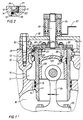
- Fig. 1 Querschnitt eines Zylinders im Demontagezustand;
- Fig. 2 Detail gemäß Linie 11 in Fig. 1 am Bund der Zylinderbuchse im fertigmontierten Zustand.
- Jeder Zylinder einer nicht weiter dargestellten Kolbenbrennkraftmaschine ist mit einer nassen Zylinderbuchse 11 ausgekleidet, deren Bund 12 versenkt in einer zylindrischen Aussparung 13 des Zylinder-Kurbelgehäuses 14 angeordnet ist. Durch zylindrische Passungen zwischen Bund 12 und Aussparung 13 sowie zwischen einer Schulter 15 der Zylinderbuchse 11 und dem Zylinder-Kurbelgehäuse 14 ist ein zentrischer, fester Sitz der Zylinderbuchse 11 im Zylinder-Kurbelgehäuse 14 gewährleistet.
- Zur Abdichtung des Kühlwasserraumes 17 gegenüber dem Kurbelraum 18 sind in der Schulter 15 elastische Dichtringe 16 angeordnet.
- Ein am Bund 12 der Zylinderbuchse 11 ausgebildeter Kühlwasserringraum 19 ist durch eine Dichtring 20 zum zylinderkofpseitigen Ende der Aussparung 13 abgedichtet.
- Am zylinderkopfseitigen Ende des Bundes 12 der Zylinderbuchse 11 ist ein zum Bund 12 konzentrisches Außengewinde 21 angeordnet.
- Das Außengewinde 21 besitzt einen gegenüber dem Außendurchmesser des Bundes 12 kleineren Außendurchmesser, wodurch eine zum Zylinderkopf weisende Planfläche 22 gebildet wird.
- Im fertig montierten Zustand der Kolbenbrennkraftmaschine (Fig. 2) ist auf das Außengewinde 21 am Bund 12 der Zylinderbuchse 11 ein Gewindering 36 aufgeschraubt, der dann die eine fehlende Nutflanke für den Dichtring 20 bildet.
- Jedem Zylinder der Kolbenbrennkraftmaschine ist eine aus Kolben 23 und Pleuel 24 bestehende Kolben-Pleuelbaugruppe zugeordnet. Das kurbelwellenseitige Lagerauge 25 des Pleuels 24 besitzt eine größere Breite als der Innendurchmesser der Zylinderbuchse 11. Die sonst übliche Montage, bei der das Pleuel 24 mit dem kurbelwellenseitigen Lagerauge 25 voran durch die bereits in das Zylinder-Kurbelgehäuse 14 eingesetzte Zylinderbuchse 11 hindurch geschoben wird, ist in diesem Fall nicht durchführbar. Deshalb ist die jedem Zylinder zugeordnete Kolben-Pleuelbaugruppe nur gemeinsam mit der zugehörigen Zylinderbuchse 11 als Einheit ein- und ausbaubar.
- Am Kolben 23, der eine Brennraummulde 29 aufweisen kann, sind symmetrisch angeordnete Einrichtungen zum Ansetzen eines Lasthebemittels ausgebildet. Die Einrichtungen können aus wenigstens zwei am Rande der Brennraummulde 29 radial nach innen vorspringende Wulstabschnitten 30 oder aus einem oder zwei axial im Kolbenboden angeordneten Gewindesacklöchern 31 bestehen.
- Für den Ein- oder Ausbau einer aus Zylinderbuchse 11, Kolben 23 und Pleuel 24 bestehende Einheit ist eine spezielle Montagevorrichtung erforderlich, die den Zusammenhalt der Bauteile zu einer Einheit bewirkt und die sichere Manipulation der Einheit während des ganzen Montagevorganges gewährleistet.
- Die Montagevorrichtung besteht aus einer glockenförmigen Platte 26, die auf das Außengewinde 21 der Zylinderbuchse 11 aufgeschraubt und gegen die Planfläche 22 verspannt wird, sowie aus einem Paar von Greifern 27 oder einem Paar von Spannschrauben 28, die mit den am Kolben 23 ausgebildeten Einrichtungen zum Ansetzen eines Lasthebemittels zusammenwirken. Mit dem Anbau der Montagevorrichtung sind die Zylinderbuchse 11 und die Kolben-Pleuelbaugruppe fest miteinander zu einer Einheit verbunden. Um ein Pendeln des Pleuels 24 während der Montage zu unterbinden, werden auf das Pleuel 24 Distanzstücke (nicht dargestellt) aufgesteckt, die sich gegen die Zylinderbuchse 11 abstützen.
- Beim Zusammenbau der Kolbenbrennkraftmaschine wird die mit der Montagevorrichtung zusammengehaltene Einheit in die Bohrung des Zylinder-Kurbelgehäuses 14 bis zum Anschnäbeln der Passung eingeführt. Durch eine Einpreßvorrichtung, die mit der Montagevorrichtung verbunden und am Zylinder-Kurbelgehäuse 14 befestigt ist, erfolgt des Einpressen der Einheit bis zur Anlage des Bundes 12 auf dem Grund der Aussparung 13. Nach Lösen und Entfernen des Werkzeugs kann der Kolben 23 in der Zylinderbuchse 11 abwärts bewegt und das Pleuel 24 mit der Kurbelwelle verbunden werden.
- Die Demontage einer Einheit erfolgt im wesentlichen in umgekehrter Reihenfolge der oben beschriebenen Handgriffe. Zunächst ist durch Entfernen des Gewinderinges 36 das Außengewinde 21 freizulegen, damit die glockenförmige Platte 26 auf die Zylinderbuchse 11 aufgeschraubt werden kann. Zylinderbuchse 11 und die Pleuelbaugruppe werden dann nach Trennen des Pleuels von der Kurbelwelle mit der Platte 26 zur Einheit verbunden. Die Kraft zum Lösen der Zylinderbuchse 11 aus dem Zylinder-Kurbelgehäuse 14 wird durch eine Auspreßvorrichtung erzeugt. Die Auspreßvorrichtung besteht aus einer Traverse 32 die über Schrauben 33 am Zylinder-Kurbelgehäuse 14 befestigt ist und einem Hydraulikzylinder 34 mit Druckölzuführung 37. Durch eine Zugstange 35 ist der Hydraulikzylinder 34 mit der glockenförmigen Platte 26 verbunden.
Claims (3)
Applications Claiming Priority (2)
| Application Number | Priority Date | Filing Date | Title |
|---|---|---|---|
| DE3803890A DE3803890C1 (de) | 1988-02-09 | 1988-02-09 | Kolbenbrennkraftmaschine mit nassen Zylinderbuchsen |
| DE3803890 | 1988-02-09 |
Publications (2)
| Publication Number | Publication Date |
|---|---|
| EP0354941A1 EP0354941A1 (de) | 1990-02-21 |
| EP0354941B1 true EP0354941B1 (de) | 1991-04-10 |
Family
ID=6346971
Family Applications (1)
| Application Number | Title | Priority Date | Filing Date |
|---|---|---|---|
| EP89901265A Expired - Lifetime EP0354941B1 (de) | 1988-02-09 | 1989-01-17 | Kolbenbrennkraftmaschine mit nassen zylinderbuchsen |
Country Status (9)
| Country | Link |
|---|---|
| US (1) | US5056470A (de) |
| EP (1) | EP0354941B1 (de) |
| JP (1) | JPH076448B2 (de) |
| KR (1) | KR940000350B1 (de) |
| CN (1) | CN1012383B (de) |
| DE (2) | DE3803890C1 (de) |
| ES (1) | ES2012916A6 (de) |
| RU (1) | RU1769777C (de) |
| WO (1) | WO1989007710A1 (de) |
Families Citing this family (12)
| Publication number | Priority date | Publication date | Assignee | Title |
|---|---|---|---|---|
| DE10151322B4 (de) * | 2001-10-17 | 2005-12-08 | Mtu Friedrichshafen Gmbh | Vorrichtung zum Ausbau einer Zylinder-Kolben-Einheit |
| CA2474472C (en) * | 2002-02-20 | 2008-05-13 | Yamaha Hatsudoki Kabushiki Kaisha | Engine fastening structure |
| DE102004024594B3 (de) * | 2004-05-18 | 2006-01-12 | Mtu Friedrichshafen Gmbh | Vorrichtung zum Ausbau einer Zylinder-Kolben-Einheit |
| JP4367288B2 (ja) * | 2004-08-17 | 2009-11-18 | トヨタ自動車株式会社 | エンジンのシリンダブロック |
| EP1803527B1 (de) * | 2005-12-23 | 2018-09-12 | GE Jenbacher GmbH & Co OG | Verfahren zum gemeinsamen Ein- und/oder Ausbau eines Kolbens und einer Zylinderlaufbuchse |
| DE102007042156A1 (de) * | 2007-09-05 | 2009-03-12 | Man Diesel Se | Verbindungsanordnung, insbesondere zum Verspannen eines Zylinderkopfes, mit einem Kurbelgehäuse einer Hubkolbenbrennkraftmaschine |
| CN102072044A (zh) * | 2011-01-24 | 2011-05-25 | 新疆阳光动力能源科技有限公司 | 水冷装置及具有该水冷装置的外燃机 |
| FR2972375B1 (fr) * | 2011-03-11 | 2014-04-11 | Renault Sa | Procede d'usinage du passage de bielle dans un carter cylindre carter cylindre et moteur obtenus par le procede |
| CN103256137B (zh) * | 2013-05-24 | 2016-04-20 | 江苏四达动力机械集团有限公司 | 湿式气缸套支撑机构 |
| CN105171394B (zh) * | 2015-10-27 | 2018-05-04 | 潍柴动力股份有限公司 | 发动机机体和曲柄连杆机构的装配、拆卸方法及装拆工装 |
| CN110173366A (zh) * | 2019-03-27 | 2019-08-27 | 潍柴动力股份有限公司 | 发动机、气缸套、缸盖及气缸套与缸盖的密封结构 |
| CN113915022B (zh) * | 2021-10-11 | 2023-03-21 | 湖南江滨机器(集团)有限责任公司 | 一种多支点活塞环限位装置及活塞 |
Family Cites Families (5)
| Publication number | Priority date | Publication date | Assignee | Title |
|---|---|---|---|---|
| JPS5012044B1 (de) * | 1971-05-27 | 1975-05-08 | ||
| JPS50696B1 (de) * | 1971-05-31 | 1975-01-10 | ||
| US3786769A (en) * | 1973-02-05 | 1974-01-22 | Singer Co | Pattern selection system |
| DE2403255A1 (de) * | 1974-01-24 | 1975-08-07 | Daimler Benz Ag | Hubkolbenmaschine mit zylinderkopf mit einer gleichmaessig steifen zylinderkopfbodenplatte |
| EP0140894B1 (de) * | 1983-05-02 | 1987-08-12 | Caterpillar Inc. | Einteilige demontierung von zylinderführung, kolben und pleuelstange |
-
1988
- 1988-02-09 DE DE3803890A patent/DE3803890C1/de not_active Expired
- 1988-12-21 ES ES8803880A patent/ES2012916A6/es not_active Expired - Lifetime
- 1988-12-22 CN CN88108782A patent/CN1012383B/zh not_active Expired
-
1989
- 1989-01-17 WO PCT/DE1989/000019 patent/WO1989007710A1/de not_active Ceased
- 1989-01-17 US US07/423,413 patent/US5056470A/en not_active Expired - Fee Related
- 1989-01-17 DE DE8989901265T patent/DE58900082D1/de not_active Expired - Lifetime
- 1989-01-17 EP EP89901265A patent/EP0354941B1/de not_active Expired - Lifetime
- 1989-01-17 KR KR1019890701850A patent/KR940000350B1/ko not_active Expired - Fee Related
- 1989-01-17 JP JP1501134A patent/JPH076448B2/ja not_active Expired - Lifetime
- 1989-10-06 RU SU894742105A patent/RU1769777C/ru active
Also Published As
| Publication number | Publication date |
|---|---|
| CN1035160A (zh) | 1989-08-30 |
| US5056470A (en) | 1991-10-15 |
| KR940000350B1 (ko) | 1994-01-17 |
| RU1769777C (ru) | 1992-10-15 |
| DE58900082D1 (de) | 1991-05-16 |
| CN1012383B (zh) | 1991-04-17 |
| WO1989007710A1 (fr) | 1989-08-24 |
| ES2012916A6 (es) | 1990-04-16 |
| JPH076448B2 (ja) | 1995-01-30 |
| JPH02503105A (ja) | 1990-09-27 |
| DE3803890C1 (de) | 1988-09-22 |
| KR900700747A (ko) | 1990-08-16 |
| EP0354941A1 (de) | 1990-02-21 |
Similar Documents
| Publication | Publication Date | Title |
|---|---|---|
| DE3803890C1 (de) | Kolbenbrennkraftmaschine mit nassen Zylinderbuchsen | |
| EP2050975B1 (de) | Vorrichtung zur reibschlüssigen Kupplung zweier koaxialer Bauteile | |
| DE3345959C2 (de) | Zylinderkopfbefestigungskonstruktion | |
| DE3120275C2 (de) | Brennkraftmaschine | |
| EP4390186B1 (de) | Dichtungssystem für unterwasserturbine | |
| DE19953475A1 (de) | Montagewerkzeug | |
| EP3129147B1 (de) | Befestigung des brechkegels in einem kegelbrecher | |
| DE3106210C2 (de) | Bohrlochkopf | |
| DE102021103307A1 (de) | Modulare Radanschlussanordnung | |
| DE4412927A1 (de) | Hydraulisch betätigbare Vorrichtung zum Ausrücken einer Schalttrennkupplung eines Kraftfahrzeugs | |
| DE2006954A1 (de) | Walzenzapfenlager | |
| DE10312412B3 (de) | Vorrichtung zum Dehnen eines Zugankers | |
| EP1933038B1 (de) | Turbomaschinengehäuse | |
| DE102014201911B4 (de) | Aktuator für einen elektrohydraulischen Gaswechselventiltrieb einer Brennkraftmaschine | |
| EP0017787B1 (de) | Abdichtung für eine Kolben-Zylinder-Anordnung | |
| DE102014201910A1 (de) | Aktuator für einen elektrohydraulischen Gaswechselventiltrieb einer Brennkraftmaschine | |
| DE2205019C2 (de) | Hydraulisch beaufschlagbare Vorspannvorrichtung für Stehbolzen | |
| EP1803527B1 (de) | Verfahren zum gemeinsamen Ein- und/oder Ausbau eines Kolbens und einer Zylinderlaufbuchse | |
| DE3710348C2 (de) | ||
| DE7018465U (de) | Wellenkupplung. | |
| DE8137709U1 (de) | Druckmaschine | |
| DE2139948A1 (de) | Verfahren zum befestigen von endstuecken an zylindern | |
| WO2013037345A1 (de) | Nehmerzylinder für ein hydraulisches ausrücksystem | |
| DE102022206730A1 (de) | Wellenanordnung | |
| DE3346220A1 (de) | Reibungskupplung |
Legal Events
| Date | Code | Title | Description |
|---|---|---|---|
| PUAI | Public reference made under article 153(3) epc to a published international application that has entered the european phase |
Free format text: ORIGINAL CODE: 0009012 |
|
| 17P | Request for examination filed |
Effective date: 19890926 |
|
| AK | Designated contracting states |
Kind code of ref document: A1 Designated state(s): CH DE FR GB IT LI |
|
| 17Q | First examination report despatched |
Effective date: 19900926 |
|
| ITF | It: translation for a ep patent filed | ||
| GRAA | (expected) grant |
Free format text: ORIGINAL CODE: 0009210 |
|
| AK | Designated contracting states |
Kind code of ref document: B1 Designated state(s): CH DE FR GB IT LI |
|
| ET | Fr: translation filed | ||
| REF | Corresponds to: |
Ref document number: 58900082 Country of ref document: DE Date of ref document: 19910516 |
|
| GBT | Gb: translation of ep patent filed (gb section 77(6)(a)/1977) | ||
| PLBE | No opposition filed within time limit |
Free format text: ORIGINAL CODE: 0009261 |
|
| STAA | Information on the status of an ep patent application or granted ep patent |
Free format text: STATUS: NO OPPOSITION FILED WITHIN TIME LIMIT |
|
| 26N | No opposition filed | ||
| PGFP | Annual fee paid to national office [announced via postgrant information from national office to epo] |
Ref country code: CH Payment date: 19941214 Year of fee payment: 7 |
|
| PG25 | Lapsed in a contracting state [announced via postgrant information from national office to epo] |
Ref country code: LI Effective date: 19960131 Ref country code: CH Effective date: 19960131 |
|
| REG | Reference to a national code |
Ref country code: CH Ref legal event code: PL |
|
| PGFP | Annual fee paid to national office [announced via postgrant information from national office to epo] |
Ref country code: GB Payment date: 19981211 Year of fee payment: 11 |
|
| PGFP | Annual fee paid to national office [announced via postgrant information from national office to epo] |
Ref country code: FR Payment date: 19981215 Year of fee payment: 11 |
|
| PGFP | Annual fee paid to national office [announced via postgrant information from national office to epo] |
Ref country code: DE Payment date: 19981217 Year of fee payment: 11 |
|
| PG25 | Lapsed in a contracting state [announced via postgrant information from national office to epo] |
Ref country code: GB Free format text: LAPSE BECAUSE OF NON-PAYMENT OF DUE FEES Effective date: 20000117 |
|
| GBPC | Gb: european patent ceased through non-payment of renewal fee |
Effective date: 20000117 |
|
| PG25 | Lapsed in a contracting state [announced via postgrant information from national office to epo] |
Ref country code: FR Free format text: LAPSE BECAUSE OF NON-PAYMENT OF DUE FEES Effective date: 20000929 |
|
| PG25 | Lapsed in a contracting state [announced via postgrant information from national office to epo] |
Ref country code: DE Free format text: LAPSE BECAUSE OF NON-PAYMENT OF DUE FEES Effective date: 20001101 |
|
| REG | Reference to a national code |
Ref country code: FR Ref legal event code: ST |
|
| PG25 | Lapsed in a contracting state [announced via postgrant information from national office to epo] |
Ref country code: IT Free format text: LAPSE BECAUSE OF NON-PAYMENT OF DUE FEES;WARNING: LAPSES OF ITALIAN PATENTS WITH EFFECTIVE DATE BEFORE 2007 MAY HAVE OCCURRED AT ANY TIME BEFORE 2007. THE CORRECT EFFECTIVE DATE MAY BE DIFFERENT FROM THE ONE RECORDED. Effective date: 20050117 |