EP0354772A2 - Vorrichtung zur Nachkalibrierung eines Aufzuglastenmesssystems - Google Patents
Vorrichtung zur Nachkalibrierung eines Aufzuglastenmesssystems Download PDFInfo
- Publication number
- EP0354772A2 EP0354772A2 EP89308074A EP89308074A EP0354772A2 EP 0354772 A2 EP0354772 A2 EP 0354772A2 EP 89308074 A EP89308074 A EP 89308074A EP 89308074 A EP89308074 A EP 89308074A EP 0354772 A2 EP0354772 A2 EP 0354772A2
- Authority
- EP
- European Patent Office
- Prior art keywords
- signal
- load
- car
- value
- stored
- Prior art date
- Legal status (The legal status is an assumption and is not a legal conclusion. Google has not performed a legal analysis and makes no representation as to the accuracy of the status listed.)
- Granted
Links
- 230000008859 change Effects 0.000 claims abstract description 34
- 230000003247 decreasing effect Effects 0.000 claims abstract description 7
- 238000000034 method Methods 0.000 claims description 17
- 238000005303 weighing Methods 0.000 claims description 7
- 238000012545 processing Methods 0.000 claims description 5
- 230000004044 response Effects 0.000 claims description 3
- 238000012360 testing method Methods 0.000 description 18
- 230000000694 effects Effects 0.000 description 4
- 238000005259 measurement Methods 0.000 description 4
- 241001246312 Otis Species 0.000 description 3
- 230000001133 acceleration Effects 0.000 description 3
- 238000012986 modification Methods 0.000 description 3
- 230000004048 modification Effects 0.000 description 3
- 230000008569 process Effects 0.000 description 3
- 230000003534 oscillatory effect Effects 0.000 description 2
- 230000004075 alteration Effects 0.000 description 1
- 230000007175 bidirectional communication Effects 0.000 description 1
- 230000002457 bidirectional effect Effects 0.000 description 1
- 230000001276 controlling effect Effects 0.000 description 1
- 238000009795 derivation Methods 0.000 description 1
- 238000010586 diagram Methods 0.000 description 1
- 238000006073 displacement reaction Methods 0.000 description 1
- 238000009826 distribution Methods 0.000 description 1
- 238000004519 manufacturing process Methods 0.000 description 1
- 239000002184 metal Substances 0.000 description 1
- 230000010355 oscillation Effects 0.000 description 1
- 230000002093 peripheral effect Effects 0.000 description 1
- 238000002360 preparation method Methods 0.000 description 1
- 230000001105 regulatory effect Effects 0.000 description 1
- 238000005070 sampling Methods 0.000 description 1
- 238000003860 storage Methods 0.000 description 1
Images

Classifications
-
- B—PERFORMING OPERATIONS; TRANSPORTING
- B66—HOISTING; LIFTING; HAULING
- B66B—ELEVATORS; ESCALATORS OR MOVING WALKWAYS
- B66B1/00—Control systems of elevators in general
- B66B1/34—Details, e.g. call counting devices, data transmission from car to control system, devices giving information to the control system
- B66B1/3476—Load weighing or car passenger counting devices
- B66B1/3484—Load weighing or car passenger counting devices using load cells
Definitions
- This invention concerns elevators, in particular, recalibrating an elevator load measuring system.
- a load line equation defines the cab load as a function of the aggregate of the transducer output signals. Passenger load, i.e. cab load, is then computed in a signal processor from the product of the aggregate and a gain coefficient; the product is then summed with an offset.
- the gain represents the slope of the line equation, the offset the value of the aggregate, theoretically zero, when the cab is empty.
- Potentiometers are adjusted to scale the aggregate of the transducer output signals to the actual load in the cab, ideally canceling out mechanically produced errors causing incorrect cab load measurement.
- U.S. patent 4,305,495 to Bittar, et al explores controlling the dispatching interval between cars to satisfy hall calls and car call demands.
- the patent explains, among other things, a way to use the cab load as determined in U.S. patent 4,330,936 in a computer-based dispatching system - an elevator in which a high-speed signal processor, such as a microprocessor, rapidly performs a wide variety of computations based on the condition of the elevator cars, cab load being one condition.
- the processor produces signals manifesting those conditions and the signals are then used by the processor to control dispatching of each car from a landing.
- the elevator performance is regulated and controlled in a scheme that provides optimal overall system performance.
- cab load is motor torquing to hold the elevator car in place after the motor brake is released in preparation for acceleration away from a landing.
- a main object of the present invention is to improve load weighing accuracy.
- the magnitude of the line equation offset determined from signals manifesting cab load produced during a previous empty car condition is compared with the magnitude of the same signals produced during a subsequent empty car condition.
- the most current signals are made the line equation offset if the difference between the current offset and the current load signal is less than or equal to a reference value. If that difference is greater than the reference value, the offset from the last empty car condition is incremented up or down by a fixed increment towards the correct magnitude, which is reached after one or more subsequent empty car tests.
- the direction and magnitude of the car "rollback" are detected (up or down, depending on the magnitude of the load).
- An occurrence of rollback is sensed initially from motor rotation while the motor is “torqued” theoretically to a level sufficient to hold the car in place without the aid of the brake.
- Rollback direction is determined from this initial rotation and is compared with the change in car position. If the directions are the same, the change in car position is stored as the rollback magnitude.
- Position change is cyclically measured and compared with rollback direction in that manner until motor velocity is commanded by a "dictation" signal. Until that takes place, the largest rollback magnitude is stored through this process, as long as it corresponds in direction to the rollback direction sensed from the motor rotation. Those position changes that are not the result of incorrect motor torquing are thereby ignored.
- the "gain" the coefficient for the load signal in the line equation that defines the load, is adjusted incrementally as a function of the magnitude and direction of the rollback.
- the gain is increased by a small increment if the rollback magnitude is less than a constant; it is increased by a higher increment if rollback magnitude is greater than or equal to that constant. If the magnitude of rollback is below a minimum value, gain is not increased at all.
- Gain recomputation is only carried out if the cab load reaches a certain load.
- gain and offset are adjusted incrementally, minimizing large changes caused by temporary system aberrations.
- the calibration process is an automatic part of the load computation routine used to provide a value for torquing the motor. Being automatic, the load weighing system is self-adjusting, always seeking the correct offset--by sensing the transducer outputs on an empty car determination--and always updating or adjusting gain until the rollback is within an acceptable range. Precise load computation is assured through an automatic procedure that takes place each time the car starts from a landing and each time an empty car condition is present.
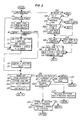
- each of two elevator car systems 1, 2, defining a "group”, contains an elevator car 3, 4, each serving a plurality of landings L1, L2, L3.
- the system shown in Fig. 1 is very similar to the system shown in the Bittar, et al patents referred to earlier and is best viewed as an example of a typical "traction" elevator system with one or more signal processors (computers) to control elevator car motion and the combined service of the cars (the group) in the building.
- each car has a counterweight 11, 12, which is connected via a cable or rope 5, 6 to the elevator car.
- the cable passes around a sheave 7, 8, rotated by an electric motor, which is not shown in Fig.1.
- Each car 3, 4 is assigned a cab controller 34, 35 and a positive position transducer (PPT).
- a traveling cable 13, 14 provides an electrical signal path for bidirectional communication between a cab controller 34, 35 and a car operation and motion controller 15, 16.
- LWINPUT a signal manifesting the cab or passenger load.
- LWINPUT is produced in response to load signals from load sensors, e.g. force transducers (TR) below the floor of the cab on each car.
- the car controllers communicate with a "group controller" 17.
- the group controller coordinates the operation of the cars through each car controller to achieve a level of group elevator service to the landings by the cars.
- Each car is connected to the PPT by a metal tape or cable 29, 30.
- a tachometer T is rotated by the sheave providing a SP signal that reflects or manifests sheave velocity (speed and direction).
- the PPT provides a POS signal that manifests the position of the car in the hoist way (elevator shaft).
- a car controller and the group controller store the instantaneous POS signal for the car, using it as information on the location of the car when establishing priorities in assigning cars to hall calls.
- the SP signal is continuously monitored and stored.
- the calibration routine of the present invention uses that information, which is continuously obtained from the PPT and the tachometer T.
- a brake BR engages the sheave when the car is stationary --at a floor.
- the brake is released (lifted from the sheave) by a brake lift (BL) signal from the car controller.
- BL brake lift
- the brake is lifted, simultaneously the motor is torqued - power is applied to the motor to hold the car in place without the brake. Then more power is provided in response to a speed dictation signal generated by the car controller, causing the car to accelerate.
- There is a short interval of time between brake lift and acceleration in which interval part of the recalibration processes presently explained takes place using the car motion that takes place if the torquing is too high or low.
- LWCORRECTED LWGAIN x (LWINPUT + LWOFFSET)
- LWCORRECTED is the "corrected passenger load", the load using the line equation recalibrated or "corrected” according to the invention.
- LWINPUT is the sum of the transducer TR signals for the car.
- LWOFFSET is the value or magnitude of LWINPUT when the cab is empty (no passengers).
- Rollback direction is sensed from the SP signal from the tachometer T.
- Rollback magnitude (on the other hand) is determined by the change in position in the POS signal. Oscillations at the car (but not the sheave) from cable elasticity can cause small bidirectional position changes until the car "settles down" before speed dictation (acceleration) commences.
- the calibration routine compares sheave motion with position change. This ignores position changes that are in the wrong direction--not representative of true rollback.
- Rollback sensing which is done to find the maximum roll-back, takes place cyclically (repetitively) until speed dictation occurs.
- LWGAIN is adjusted higher or lower--so that on the next calibration sequence (when the car again starts) the rollback will be less.
- the routine it will be shown, takes place each time the car starts with a passenger load exceeding a preset level and continues until speed dictation begins.
- LWOFFSET also impacts torquing; for that reason, actual LWGAIN modification or adjustment takes place only if LWOFFSET is within an acceptable range. Otherwise, rollback is sensed and stored but not used to adjust LWGAIN.
- the LWGAIN and LWOFFSET recalibration routine begins by moving to a first test S1 which determines whether the car speed dictation signal has been applied to the motor; that is, the car is "running" (moving or about to move).
- the speed dictation signal is produced following a short interval after the brake is lifted by the BL signal, at which point in time the motor is given a pretorquing signal, ideally sufficient to cause the car to remain in place after the brake is lifted.
- the recalibration routine will also sense as a running condition a releveling signal to the motor.
- a releveling signal is produced by the car controller to cause the car to level if it drops outside the "level zone", usually a band of .25 inches above and below floor level.
- the recalibration technique then moves to step S2, which queries whether the "empty car flag" has been set from an empty car determination routine (preferably by following the routines set out in U.S. patent 4,299,309). Assuming that an empty car flag is set, that leads to an adjustment of LWOFFSET. This discussion also assumes that when the empty car condition was sensed the signals LWINPUT from the transducers were also stored.
- the empty car flag is reset.
- step S4 the transducer outputs are read as the "LWINPUT".
- the current offset "LWOFFSET” is read at step S5. This is a latest value for LWOFFSET, as determined by the same routine - but following an earlier empty car determination.
- the object of the sequence is to determine whether that latest (current) LWOFFSET is correct.
- step S6 a test is made to determine whether the difference between LWINPUT and LWOFFSET is less than or equal to a constant "STEP" (an error). Assuming that the difference is greater than or equal to STEP, step S7 adds STEP to the LWOFFSET, which now becomes LWOFFSET in equation 1.
- step S8 an "invalid" flag is set.
- the "invalid” flag is used later to show that the line equation has not been recalibrated to the point that the difference between the zero load condition and the load associated with the stored LWOFFSET is sufficiently small that LWGAIN can be adjusted accurately. (An LWOFFSET adjustment should not compensate for inaccurate LWGAIN and vice versa).
- the routine compares the absolute value of LWINPUT-LWOFFSET with STEP so that when LWOFFSET exceeds LWINPUT by more than STEP, STEP is substracted from LWOFFSET in step S7.
- the value which is added to LWOFFSET in set S7 need not be the same value STEP as used in the test step S6.
- step S9 LWOFFSET is made the same as LWINPUT, meaning that now there is no difference between the no-load condition and the zero load value for LWOFFSET.
- a "valid" flag is set at step S10. The "valid" flag, when present, allows the LWGAIN adjustment to take place in a later part of the routine because the line equation is devoid of any errors in LWOFFSET at the time the measurements of rollback are made.
- LWOFFSET is thus adjusted in the previous sequences either to the current level of the transducer outputs (LWINPUT) or to some new level which was the previous LWOFFSET plus (or minus) STEP but less than LWINPUT.
- step S11 a test is made to determine whether the brake is OFF, meaning that the brake has been lifted and the car is about to accelerate from the floor or landing. If the the brake is still ON, (BL signal is not present) steps S12 - S15 initialize parameters used in the subsequent LWGAIN adjustment sequences.
- step S12 the current position of the car, the POS signal, is stored. The speed dictation flag is set to OFF in step S13.
- step S14 the rollback direction is set to zero. And, in step S15, the rollback magnitude is set to zero.
- Step S15 the routine returns (repeats from "begin”). It continues the cycle until the test ac S11 is positive--because the brake is lifted.
- Step S16 asks whether there is a dictation flag.
- a dictation flag is raised in a previous cycle when a speed dictation signal (to accelerate or relevel the car) is produced by the controller.
- the motor is given a signal to torque it to hold the car in place.
- the signal is proportional to LWCORRECTED, a load computed using adjustments made to LWGAIN and LWOFFSET using this calibration routine, but at a prior floor stop. (A speed dictation command, "DICTATION", on the other hand, causes the car to accelerate.)
- step S17 the routine cyclically tests the rollback while the motor is torqued but not commanded to accelerate (no dictation) at step S17.
- An affirmative answer at step S16 causes the routine to return beginning at step S1, where, once again, the test shows that the car is still not running. (A positive answer, it will be shown, causes the routine to move to a gain adjustment sequence, where the rollback direction and magnitude are used to increase or decrease the LWGAIN in incremental steps depending on rollback magnitude).
- step S18 assumes that a dictation flag signal has not been raised and thus the sequence moves from step S16 to step S18.
- a test is made to determine whether the rollback direction is equal to zero. If it is equal to zero, the routine is then recycled, through RETURN. If the rollback direction is equal to zero, rollback direction is set to be the same as the machine velocity. This is done by retrieving the output SP from the tachometer. The tachometer T, of course, will provide an indication of the small motion of the rotation of the motor sheave 7, 8. At step S19, the rollback direction is made non-zero.
- step S18 moves the routine to step S21, where the greatest rollback magnitude is stored.
- This routine of sampling position change occurs very rapidly throughout the interval before speed dictation and following the lifting of the brake. Following brake lift, the car will start to move either up or down slightly, perhaps even with an oscillatory motion. It is an object of the sequence to sense the greatest rollback magnitude yet at the same time ignore the changes in rollback that are associated with oscillatory movement. These are changes in car position that are not associated with inadequate motor torquing to hold the car in place without the brake. Long time constants in an elevator cause unphased movements of the car and sheave. At some point in time, not necessarily before speed dictation, the car and sheave stop moving.
- step S21 a coincidence test in effect, a test is made to determine whether rollback, the change in position sensed by the tachometer, is in the same direction as the actual change in position shown by any change in the POS signal provided by the PPT. If the directions are not the same, step S21 causes the routine to recycle; as a result rollback, initialized at zero in step S15, is left unchanged. If, however, step S21 yields a positive answer (the directions are the same), at step S22 rollback is made to equal the change in position (measured from the change in the POS signal).
- the rollback signal is no longer equal to zero and the routine again cycles through the beginning to examine rollback at a second point in time, when it will store the next sensed change in position as the rollback - if it is greater than the previously stored value and in the same direction as the change in sheave position.
- the routine finds a positive answer to the running test at S1.
- the routine would then move to step S23, leaving the portion in which rollback is cyclically sensed and the maximum change in rollback position is stored and allowing the routine to move into the steps to actually change LWGAIN based on the magnitude and direction of the stored rollback.
- step S23 the test determines if there is a valid flag.
- the valid flag is set at step S10 if the condition of LWINPUT equaling LWOFFSET is satisfied.
- An adjustment of the gain based upon the rollback should not be made unless it is first determined that the offset of the system is within some acceptable limits. For instance, if it is determined in step S6 that the difference between LWINPUT and LWOFFSET is greater than or equal to STEP the offset is only partially eliminated. Consequently, a LWGAIN adjustment should not be made (steps S23 - S41) because LWGAIN will be adjusted because of an error in offset, not the line slope (LWGAIN) in equation 1.
- step S23 yields an affirmative answer, moving the routine to step S24.
- This test finds, using the load computed at step S20, if the current corrected load weight (using the LWOFFSET and unadjusted current LWGAIN values) exceeds a minimum level. If the passenger load is not high enough the routine ignores the rollback data collected, assuming, in effect, that the results are not reliable at low load levels. Passenger load greater than or equal to 60% of full load is the preferred minimum, a condition occurring typically during the up-peak period, e.g. the morning in an office building.
- Step S25 is entered following an affirmative answer to step S24.
- Step S25 determines whether the rollback is greater than or equal to a value (MIN.). If it is, a high incremental change in the gain is commanded in step S44. Then, in step S26, a test is made to determine whether the rollback exceeds a minimum level (MIN.A). If not, the routine is exited. The assumption is that no adjustment is needed if the rollback is small. If rollback is greater than MIN.A but less than MIN., it is in a range commanding a "low" incremental change. Both steps S27 and S44 lead to testing, at step S28, to find if the rollback increment, be it high or low, must be added to or subtracted from the current LWGAIN.
- pretorquing is inadequate, as indicated by the rollback in one direction, LWGAIN will have to be increased through step S29. If pretorquing is excessive, causing rollback in the opposite direction, LWGAIN will have to be decreased at step S30. As a practical matter, if LWGAIN is low the rollback will be towards a lower floor (down) if the adjustment is done with at least 60% of full load.
- step S40 LWGAIN is set to equal current LWGAIN plus the gain step (it may be plus or minus from steps S29 and S30 and either the high level or low level). Then in step S41, the rollback flag, set at step S15, is set back to zero (turned off) and the routine is then exited, LWGAIN having been adjusted for the next load computation, when the rollback test will again be conducted.
- passenger load (cab load) is computed using the most recently determined LWOFFSET and LWGAIN (the most current load line equation). Absent a rollback value, the routine cannot be entered until a rollback value is again set when the brake is lifted, which takes place at the next stop at a landing.
Landscapes
- Engineering & Computer Science (AREA)
- Mechanical Engineering (AREA)
- Automation & Control Theory (AREA)
- Computer Networks & Wireless Communication (AREA)
- Elevator Control (AREA)
- Indicating And Signalling Devices For Elevators (AREA)
- Maintenance And Inspection Apparatuses For Elevators (AREA)
Priority Applications (1)
| Application Number | Priority Date | Filing Date | Title |
|---|---|---|---|
| EP94111428A EP0626333B1 (de) | 1988-08-09 | 1989-08-09 | Vorrichtung zur Nachkalibrierung eines Aufzugslastmesssystems |
Applications Claiming Priority (2)
| Application Number | Priority Date | Filing Date | Title |
|---|---|---|---|
| US07/230,384 US4939679A (en) | 1988-08-09 | 1988-08-09 | Recalibrating an elevator load measuring system |
| US230384 | 1988-08-09 |
Related Child Applications (2)
| Application Number | Title | Priority Date | Filing Date |
|---|---|---|---|
| EP94111428.2 Division-Into | 1989-08-09 | ||
| EP94111428A Division EP0626333B1 (de) | 1988-08-09 | 1989-08-09 | Vorrichtung zur Nachkalibrierung eines Aufzugslastmesssystems |
Publications (3)
| Publication Number | Publication Date |
|---|---|
| EP0354772A2 true EP0354772A2 (de) | 1990-02-14 |
| EP0354772A3 EP0354772A3 (de) | 1991-11-13 |
| EP0354772B1 EP0354772B1 (de) | 1995-02-08 |
Family
ID=22865015
Family Applications (2)
| Application Number | Title | Priority Date | Filing Date |
|---|---|---|---|
| EP89308074A Expired - Lifetime EP0354772B1 (de) | 1988-08-09 | 1989-08-09 | Vorrichtung zur Nachkalibrierung eines Aufzuglastenmesssystems |
| EP94111428A Expired - Lifetime EP0626333B1 (de) | 1988-08-09 | 1989-08-09 | Vorrichtung zur Nachkalibrierung eines Aufzugslastmesssystems |
Family Applications After (1)
| Application Number | Title | Priority Date | Filing Date |
|---|---|---|---|
| EP94111428A Expired - Lifetime EP0626333B1 (de) | 1988-08-09 | 1989-08-09 | Vorrichtung zur Nachkalibrierung eines Aufzugslastmesssystems |
Country Status (5)
| Country | Link |
|---|---|
| US (1) | US4939679A (de) |
| EP (2) | EP0354772B1 (de) |
| JP (1) | JP2625550B2 (de) |
| AU (1) | AU623877B2 (de) |
| DE (2) | DE68927757T2 (de) |
Cited By (3)
| Publication number | Priority date | Publication date | Assignee | Title |
|---|---|---|---|---|
| ES2150364A1 (es) * | 1998-06-22 | 2000-11-16 | Micelect S L | Instrumento de medida de masas colgantes para maquinas que funcionan con cables de traccion. |
| WO2006119787A1 (en) * | 2005-05-09 | 2006-11-16 | Otis Elevator Company | Method for controlling an elevator drive device and related operartion device for an elevator system |
| EP2813458A1 (de) * | 2013-06-10 | 2014-12-17 | Kone Corporation | Verfahren und Vorrichtung zur Schätzung des Gewichts einer Aufzugskabine |
Families Citing this family (21)
| Publication number | Priority date | Publication date | Assignee | Title |
|---|---|---|---|---|
| US6344089B1 (en) * | 1977-08-15 | 2002-02-05 | Mitsubishi Denki Kabushiki Kaisha | Drive control for elevator |
| US5343003A (en) * | 1992-05-29 | 1994-08-30 | Otis Elevator Company | Recalibration of hitch load weighing using dynamic tare |
| US5345042A (en) * | 1992-05-29 | 1994-09-06 | Otis Elevator Company | Elevator hitch load weighing tare compensation |
| DE69401667T2 (de) * | 1993-03-04 | 1997-05-28 | Otis Elevator Co | Vorstromdrehmoment für Aufzugsantrieb zur Vermeidung eines Gleitens nach oben wie nach unten |
| US5407030A (en) * | 1993-03-04 | 1995-04-18 | Otis Elevator Company | Recalibrating an elevator loadweighing system |
| JPH06321440A (ja) * | 1993-05-11 | 1994-11-22 | Mitsubishi Electric Corp | エレベーターの制御装置 |
| EP1986945A4 (de) * | 2006-02-14 | 2011-12-21 | Otis Elevator Co | Zustandstest für aufzugsbremse |
| FI120193B (fi) * | 2008-01-09 | 2009-07-31 | Kone Corp | Hissijärjestelmän liikkeenohjaus |
| WO2009108186A1 (en) * | 2008-02-26 | 2009-09-03 | Otis Elevator Company | Dynamic compensation during elevator car re-leveling |
| FR2928124B1 (fr) * | 2008-02-29 | 2012-02-10 | Pomagalski Sa | Procede de controle d'un organe de freinage ou de mise en mouvement auxiliaire d'une installation de transport par cable. |
| DE102011101860A1 (de) | 2011-05-12 | 2012-11-15 | Thyssenkrupp Aufzugswerke Gmbh | Verfahren und Vorrichtung zum Steuern einer Aufzugsanlage |
| DE102011105342A1 (de) | 2011-06-21 | 2012-12-27 | Thyssenkrupp Aufzugswerke Gmbh | Verfahren zum Ermitteln des Trägheitsmoment-Faktors einer Motoranordnung einer Aufzugsanlage |
| EP2774885B1 (de) * | 2013-03-04 | 2016-05-18 | Kone Corporation | Verfahren zur Durchführung einer Gleichgewichtsprüfung mit einem Aufzug |
| CN103287937B (zh) * | 2013-05-09 | 2015-09-09 | 深圳市海浦蒙特科技有限公司 | 电梯起动转矩自动调节方法及系统 |
| CN103387165B (zh) * | 2013-08-08 | 2016-10-05 | 广州市寰宇电子科技有限公司 | 电梯载重检测方法以及系统 |
| CN103663007B (zh) * | 2013-12-17 | 2015-08-12 | 叶荣伟 | 一种节能型曳引式电梯及其节能方法 |
| CN106144797B (zh) * | 2015-04-03 | 2020-11-27 | 奥的斯电梯公司 | 用于乘客运输的通行列表产生 |
| EP3601131B1 (de) * | 2017-03-31 | 2022-05-11 | Inventio AG | Aufzugskabinenlastmesssystem und verfahren zur bestimmung einer last einer aufzugskabine |
| EP3406559A1 (de) | 2017-05-24 | 2018-11-28 | Otis Elevator Company | Personenförderer |
| US11987472B2 (en) * | 2019-05-01 | 2024-05-21 | Otis Elevator Company | Air pressure sensor algorithm to detect elevator direction of motion |
| EP3960674B1 (de) | 2020-08-26 | 2025-06-18 | Appana Industries LLC | Systeme und verfahren zur einstellung der aufzugslast |
Family Cites Families (10)
| Publication number | Priority date | Publication date | Assignee | Title |
|---|---|---|---|---|
| CH429904A (de) * | 1965-04-01 | 1967-02-15 | Inventio Ag | Anordnung zur Erzielung eines ruckfreien Anfahrens bei einem elektrischen Antrieb mit mechanischer Haltebremse |
| GB2064796B (en) * | 1979-11-28 | 1984-06-27 | Otis Elevator Co | Elevator cab load measuring system |
| US4330836A (en) * | 1979-11-28 | 1982-05-18 | Otis Elevator Company | Elevator cab load measuring system |
| US4305479A (en) * | 1979-12-03 | 1981-12-15 | Otis Elevator Company | Variable elevator up peak dispatching interval |
| US4299309A (en) * | 1979-12-27 | 1981-11-10 | Otis Elevator Company | Empty elevator car determination |
| JPS5842573A (ja) * | 1981-09-04 | 1983-03-12 | 株式会社日立製作所 | エレベ−タ−の制御装置 |
| US4501343A (en) * | 1982-10-12 | 1985-02-26 | Otis Elevator Company | Elevator car load and position dynamic gain compensation |
| US4674605A (en) * | 1986-04-18 | 1987-06-23 | Otis Elevator Company | Automatic elevator load sensor calibration system |
| ATE64355T1 (de) * | 1987-05-27 | 1991-06-15 | Inventio Ag | Aufzugsantrieb mit regeleinrichtung fuer ruckfreies anfahren. |
| US4793442A (en) * | 1987-11-05 | 1988-12-27 | Schindler Elevator Corporation | Method and apparatus for providing pre-travel balancing energy to an elevator drive |
-
1988
- 1988-08-09 US US07/230,384 patent/US4939679A/en not_active Expired - Fee Related
-
1989
- 1989-02-08 AU AU29767/89A patent/AU623877B2/en not_active Ceased
- 1989-08-09 EP EP89308074A patent/EP0354772B1/de not_active Expired - Lifetime
- 1989-08-09 EP EP94111428A patent/EP0626333B1/de not_active Expired - Lifetime
- 1989-08-09 DE DE68927757T patent/DE68927757T2/de not_active Expired - Fee Related
- 1989-08-09 DE DE68921028T patent/DE68921028T2/de not_active Expired - Fee Related
- 1989-08-09 JP JP1206584A patent/JP2625550B2/ja not_active Expired - Lifetime
Cited By (3)
| Publication number | Priority date | Publication date | Assignee | Title |
|---|---|---|---|---|
| ES2150364A1 (es) * | 1998-06-22 | 2000-11-16 | Micelect S L | Instrumento de medida de masas colgantes para maquinas que funcionan con cables de traccion. |
| WO2006119787A1 (en) * | 2005-05-09 | 2006-11-16 | Otis Elevator Company | Method for controlling an elevator drive device and related operartion device for an elevator system |
| EP2813458A1 (de) * | 2013-06-10 | 2014-12-17 | Kone Corporation | Verfahren und Vorrichtung zur Schätzung des Gewichts einer Aufzugskabine |
Also Published As
| Publication number | Publication date |
|---|---|
| EP0354772B1 (de) | 1995-02-08 |
| JP2625550B2 (ja) | 1997-07-02 |
| DE68921028D1 (de) | 1995-03-23 |
| US4939679A (en) | 1990-07-03 |
| DE68921028T2 (de) | 1995-08-03 |
| AU623877B2 (en) | 1992-05-28 |
| EP0626333A1 (de) | 1994-11-30 |
| EP0354772A3 (de) | 1991-11-13 |
| JPH02100979A (ja) | 1990-04-12 |
| DE68927757T2 (de) | 1997-05-28 |
| AU2976789A (en) | 1990-02-15 |
| EP0626333B1 (de) | 1997-02-05 |
| DE68927757D1 (de) | 1997-03-20 |
Similar Documents
| Publication | Publication Date | Title |
|---|---|---|
| EP0354772B1 (de) | Vorrichtung zur Nachkalibrierung eines Aufzuglastenmesssystems | |
| US6488128B1 (en) | Integrated shaft sensor for load measurement and torque control in elevators and escalators | |
| CN103097272B (zh) | 用于控制电梯设备的传动机的方法以及实施该方法的装置 | |
| US5035301A (en) | Elevator speed dictation system | |
| CN1036643C (zh) | 控制并且自动校正电梯或提升机的轿厢减速/停止指令的方法和装置 | |
| US7992689B2 (en) | Movement control of an elevator system using position deviation to determine loading state | |
| US4793442A (en) | Method and apparatus for providing pre-travel balancing energy to an elevator drive | |
| GB2071358A (en) | Method of and system for lift control | |
| EP0807084B1 (de) | Steuerungsverfahren und -vorrichtung für aufzughebemotor | |
| US4936136A (en) | Method for checking the friction between the traction sheeve and the suspension ropes of an elevator | |
| HK97097A (en) | Bias torque for elevator hoist drive to avoid rollback, rollforward | |
| CN1300708A (zh) | 电梯的制动转矩调整装置 | |
| CN111807169B (zh) | 一种电梯负载率实时监控方法 | |
| US5441127A (en) | Elevator control apparatus | |
| CA1290478C (en) | Method for providing a load compensation signal for a traction elevator system | |
| JP4230139B2 (ja) | エレベータの制御装置 | |
| EP0074093A2 (de) | Aufzugsteuerungssystem | |
| CA1285082C (en) | Method and apparatus for providing a load compensation signalfor a traction elevator system | |
| JPS622872A (ja) | 移動体の移動用電気モ−タ−の調節制御方法およびそれを実施するための制御装置 | |
| US5848671A (en) | Procedure for stopping an elevator at a landing | |
| WO1992018411A1 (en) | Method of controlling a plurality of elevators moving in a common hoistway | |
| CN113905967A (zh) | 调节量计算装置以及电梯装置的调节方法 | |
| CN114955762A (zh) | 提高电梯平层精度的装置 | |
| JP2005170537A (ja) | エレベータの制御装置 | |
| CA2240106A1 (en) | Method and device for the regulation of a drive |
Legal Events
| Date | Code | Title | Description |
|---|---|---|---|
| PUAI | Public reference made under article 153(3) epc to a published international application that has entered the european phase |
Free format text: ORIGINAL CODE: 0009012 |
|
| AK | Designated contracting states |
Kind code of ref document: A2 Designated state(s): CH DE FR GB LI |
|
| PUAL | Search report despatched |
Free format text: ORIGINAL CODE: 0009013 |
|
| AK | Designated contracting states |
Kind code of ref document: A3 Designated state(s): CH DE FR GB LI |
|
| 17P | Request for examination filed |
Effective date: 19920508 |
|
| 17Q | First examination report despatched |
Effective date: 19930913 |
|
| GRAA | (expected) grant |
Free format text: ORIGINAL CODE: 0009210 |
|
| AK | Designated contracting states |
Kind code of ref document: B1 Designated state(s): CH DE FR GB LI |
|
| XX | Miscellaneous (additional remarks) |
Free format text: TEILANMELDUNG 94111428.2 EINGEREICHT AM 09/08/89. |
|
| ET | Fr: translation filed | ||
| REF | Corresponds to: |
Ref document number: 68921028 Country of ref document: DE Date of ref document: 19950323 |
|
| PLBE | No opposition filed within time limit |
Free format text: ORIGINAL CODE: 0009261 |
|
| STAA | Information on the status of an ep patent application or granted ep patent |
Free format text: STATUS: NO OPPOSITION FILED WITHIN TIME LIMIT |
|
| 26N | No opposition filed | ||
| PGFP | Annual fee paid to national office [announced via postgrant information from national office to epo] |
Ref country code: GB Payment date: 19960723 Year of fee payment: 8 |
|
| PGFP | Annual fee paid to national office [announced via postgrant information from national office to epo] |
Ref country code: DE Payment date: 19960724 Year of fee payment: 8 |
|
| PGFP | Annual fee paid to national office [announced via postgrant information from national office to epo] |
Ref country code: FR Payment date: 19970710 Year of fee payment: 9 |
|
| PGFP | Annual fee paid to national office [announced via postgrant information from national office to epo] |
Ref country code: CH Payment date: 19970731 Year of fee payment: 9 |
|
| PG25 | Lapsed in a contracting state [announced via postgrant information from national office to epo] |
Ref country code: GB Free format text: LAPSE BECAUSE OF NON-PAYMENT OF DUE FEES Effective date: 19970809 |
|
| GBPC | Gb: european patent ceased through non-payment of renewal fee |
Effective date: 19970809 |
|
| PG25 | Lapsed in a contracting state [announced via postgrant information from national office to epo] |
Ref country code: DE Free format text: LAPSE BECAUSE OF NON-PAYMENT OF DUE FEES Effective date: 19980501 |
|
| PG25 | Lapsed in a contracting state [announced via postgrant information from national office to epo] |
Ref country code: LI Free format text: LAPSE BECAUSE OF NON-PAYMENT OF DUE FEES Effective date: 19980831 Ref country code: CH Free format text: LAPSE BECAUSE OF NON-PAYMENT OF DUE FEES Effective date: 19980831 |
|
| REG | Reference to a national code |
Ref country code: CH Ref legal event code: PL |
|
| PG25 | Lapsed in a contracting state [announced via postgrant information from national office to epo] |
Ref country code: FR Free format text: LAPSE BECAUSE OF NON-PAYMENT OF DUE FEES Effective date: 19990430 |
|
| REG | Reference to a national code |
Ref country code: FR Ref legal event code: ST |