EP0353539B1 - Beweglicher Stecker und Kupplung für elektrische Kabel - Google Patents
Beweglicher Stecker und Kupplung für elektrische Kabel Download PDFInfo
- Publication number
- EP0353539B1 EP0353539B1 EP89113137A EP89113137A EP0353539B1 EP 0353539 B1 EP0353539 B1 EP 0353539B1 EP 89113137 A EP89113137 A EP 89113137A EP 89113137 A EP89113137 A EP 89113137A EP 0353539 B1 EP0353539 B1 EP 0353539B1
- Authority
- EP
- European Patent Office
- Prior art keywords
- terminal plate
- clamping device
- arm
- integral
- arms
- Prior art date
- Legal status (The legal status is an assumption and is not a legal conclusion. Google has not performed a legal analysis and makes no representation as to the accuracy of the status listed.)
- Expired - Lifetime
Links
Images

Classifications
-
- H—ELECTRICITY
- H01—ELECTRIC ELEMENTS
- H01R—ELECTRICALLY-CONDUCTIVE CONNECTIONS; STRUCTURAL ASSOCIATIONS OF A PLURALITY OF MUTUALLY-INSULATED ELECTRICAL CONNECTING ELEMENTS; COUPLING DEVICES; CURRENT COLLECTORS
- H01R13/00—Details of coupling devices of the kinds covered by groups H01R12/70 or H01R24/00 - H01R33/00
- H01R13/58—Means for relieving strain on wire connection, e.g. cord grip, for avoiding loosening of connections between wires and terminals within a coupling device terminating a cable
- H01R13/5804—Means for relieving strain on wire connection, e.g. cord grip, for avoiding loosening of connections between wires and terminals within a coupling device terminating a cable comprising a separate cable clamping part
Definitions
- the present invention relates to the free connectors equipped with cable clamping devices, such connectors normally used as trailing sockets and plugs.
- the aim of the cable clamping device is to clamp the cable to the plug or socket, preventing it from being unintentionally extracted owing to traction being exercised on it, either as the result of a mistake in operation or in the case of an accident.
- Connectors including cable clamping devices are known from e.g. DE-A-2433347
- the cable clamping devices prevent the connecting terminals from being subjected to traction and prevent the cable itself from being disconnected from the terminal plate of the connector, thereby causing serious trouble.
- Cable clamping devices made of plastic material are well-known where two tongues of the same material extend from the periphery of the terminal plate and, at the opposite end with respect to the terminal plate, broaden into two coupling brackets, inside which the electric cable is inserted. After the cable is inserted, the clamps are locked one against the other by means of a pair of screws, with their respective nuts, thus carrying out fixing of the cable inserted between them.
- the device described has some disadvantages, such as:
- Aim of the present invention is to produce a clamping device for trailing sockets and plugs which is able to avoid the difficulties mentioned above, that is one which facilitates cable connections, allows an identical terminal plate to be contructed for stationarily mounted and trailing sockets and plugs, and facilitates installation.
- an electrical connector according to Claim 1 comprising a terminal plate and a clamping device which are integral with said terminal plate during use, in which said clamping device and said terminal plate consist of two separate elements, each equipped with a reciprocal engaging means, said connector characterized in that said engaging means consists, as regards the clamping device, of a pair of arms integral with said device, the arms being integral with just one of the two coupling brackets suitable for receiving the electric cable between them, at least one of the two arms having an enlarged head at its free end, capable of locking into a hole provided on the terminal plate.
- One arm can also be equipped with a seat capable of being received into a peripheral slot provided on the terminal plate, provision being made in this case for the rotation of the engaging means of the other arm with respect to the terminal plate.
- the seat ends in a collar which prevents the arm from escaping.
- the clamping of the cable into the clamping device is performed preferably by inserting the jagged wings of one bracket inside the corresponding openings of the other bracket, one wall of which is defined by a tongue suitable of cooperating with said jagged wings.
- the connection is detachable by operating upon resilient wings which allow said tongue to disengage from the jagged wings.
- the two brackets are joined together during moulding by a metal strip.
- the clamping device comprises a clamping bracket 3 and a bracket 1 equipped with two equal symmetrical wings 2a and 2b.
- the two brackets 1 and 3 are joined together by means of a narrow strip 4.
- the wings 2a and 2b of the bracket 1 are jagged on their inner side.
- the bracket 3 consists of a central part 5 suitable for receiving the cable, and of two equal openings 6a and 6b, inside which two elastic tongues 7a and 7b are provided respectively, which are equal and symmetrical and suitable for engaging with the jagging teeth of the wings 2a and 2b.
- the tongues 7a and 7b are each provided with a wing 7c and 7d, respectively, which is resilient and projects in a perpendicular direction with respect to the tongues 7a and 7b themselves.
- the central part 5 of the bracket 3 in which the electric cable is housed is equipped with four projecting elements 8a, 8b 8c and 8d, having a conical shape with a rounded top, to ensure a better grip on the cable.
- the arm 9 ends in a head 12 above which an abutment 12a is provided.
- the arm is also equipped with a collar 11 for acting as a further ledge which can serve as a stop during wiring.
- the arm 10 ends in a seat 13 comprised between two collars, one of them, 14, located at the end and the other, 13a, more internally.
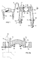
- the terminal plate 21, to which the trailing socket, plug or such is connected is equipped, as is already known, with holes 24a, 24b, and 24c respectively, into which the wires will be inserted to carry out the connection.
- the terminal plate is further equipped with fixing holes 22a and 22b and possibly with a notch 23.
- the terminal plate 21 is equipped with a further throughhole 25, along its periphery.
- This hole is internally provided with four equal projections 26a, 26b, 26c and 26d, which extend into the plug- or socket housing.
- the configuration of the walls of the hole 25 can be better seen in figure 3, where two of the projections, in particular 26c and 26d, are to be seen.
- the arm 9 (see figure 1) of the clamping device is positioned over the hole 25; the foremost part of the arm 9 with its hemispherical head 12 is then inserted into the hole 25.
- the heads 12 slides within the projections 26a, 26b, 26c and 26d, and finally protrudes from the hole 25.
- the projections 26a, 26b, 26c and 26d rest on the lower base of the head 12, where the diameter of the arm 9 is narrower and prevents the arm 9 from being extracted from the terminal board 21.
- the other arm 10 of the bracket 3 is made to rotate relatively to the arm 9 and positioned in correspondence with the slot 27. Then the arm 10 is pressed into the slot 27, slides along it and comes to abut against the semicircular rounded form at the terminal end of the slot.
- bracket 3 is near to the cable which, in order to be clamped, has only to be gripped by the other bracket 1 whose wings 2a, 2b, are made to penetrate the openings 6a and 6b.
- bracket 1 If it is desired to disconnect bracket 1 from bracket 3, in order to release the cable, it is sufficient to slightly push on the wings 7c and 7d, by hand or by means of a tool, bringing said wings nearer to each other. In this way, the tongues 7a and 7b disengage from the jagging teeth of the wings 2a and 2b, which can be withdrawn from openings 6a and 6b.
Landscapes
- Coupling Device And Connection With Printed Circuit (AREA)
- Connector Housings Or Holding Contact Members (AREA)
- Details Of Connecting Devices For Male And Female Coupling (AREA)
- Insulated Conductors (AREA)
Claims (4)
- Stecker- und buchsenförmiger Verbinder bestehend aus einer Endplatte (21) und einer Klemmvorrichtung (1, 3), die während der Verwendung ein einteiliges Stück mit der gesagten Endplatte (21) bildet, die genannte Klemmvorrichtung (1, 3) und die gesagte Endplatte (21) aus zwei getrennten Elementen bestehend, wobei jedes mit einem gegenseitigen Verbindungsmittel versehen ist, dadurch gekennzeichnet, daß die genannten gegenseitigen Bindemittel ein paar Arme (9, 10) beinhalten, welche ein einteliges Stück mit der gesagten Klemmvorrichtung (1, 3) bilden und geformte Endteile aufweisen, wobei mindestens ein Arm (9) an seinem freien Endteil mit einem vergrößerten Kopf (12) ausgestattet ist, der in ein Durchlaufloch (25) gesperrt werden kann, das an der Endplatte (21) vorgesehen ist, da beide genannte Arme (9, 10) mit nur einer (3) der beiden Kupplungsbügel (1, 3) ein einteliges Stück bilden, welche die Klemmvorrichtung darstellen.
- Verbinder nach Anspruch 1 dadurch gekennzeichnet, daß der Arm (10) an seinem freien Endteil mit einem Sitz (13) versehen ist, der in einem vorgesehenen Peripherhohlraum (27) der Endplatte (21) aufgennomen werden kann, da der Arm (10) außenseits durch ein Anschlagbund (14) begrenzt ist, insoweit eine Drehung des anderen Verbindungsmittels (9) gegenüber der Endplatte (21) vorgesehen ist.
- Verbinder nach Anspruch 1 oder 2, dadurch gekennzeichnet, daß einer der Bügel (1) mit Zahnflügeln (2a, 2b) und der andere (3) mit entsprechenden Öffnungen (6a, 6b) versehen ist, wobei eine Seite derselben durch eine Lasche (7a, 7b) bestimmt ist, die mit den genannten Zahnflügeln (2a, 2b) zusammenarbeiten kann, da die genannte Lasche (7a, 7b) mit einem Spannflügel (7c, 7d) versehen ist, der das Ausschalten der Lasche (7a, 7b) aus der Zahnung der Flügel (2a, 2b) und die nachfolgende Herausnahme der Flügel (2a, 2b) aus den Öffnungen (6a, 6b) erlaubt.
- Verbinder nach einen jeglichen der bevorstehenden Ansprüchen, dadurch gekennzeichnet, daß beide Bügel (1, 3) während des Gesenkschmiedens durch ein Metallband (4) verbunden werden.
Priority Applications (1)
| Application Number | Priority Date | Filing Date | Title |
|---|---|---|---|
| AT89113137T ATE84643T1 (de) | 1988-07-29 | 1989-07-18 | Beweglicher stecker und kupplung fuer elektrische kabel. |
Applications Claiming Priority (2)
| Application Number | Priority Date | Filing Date | Title |
|---|---|---|---|
| IT8821590A IT1227022B (it) | 1988-07-29 | 1988-07-29 | Connettore per cavi elettrici a spina e presa volante. |
| IT2159088 | 1988-07-29 |
Publications (2)
| Publication Number | Publication Date |
|---|---|
| EP0353539A1 EP0353539A1 (de) | 1990-02-07 |
| EP0353539B1 true EP0353539B1 (de) | 1993-01-13 |
Family
ID=11184034
Family Applications (1)
| Application Number | Title | Priority Date | Filing Date |
|---|---|---|---|
| EP89113137A Expired - Lifetime EP0353539B1 (de) | 1988-07-29 | 1989-07-18 | Beweglicher Stecker und Kupplung für elektrische Kabel |
Country Status (5)
| Country | Link |
|---|---|
| EP (1) | EP0353539B1 (de) |
| AT (1) | ATE84643T1 (de) |
| DE (1) | DE68904375T2 (de) |
| ES (1) | ES2037345T3 (de) |
| IT (1) | IT1227022B (de) |
Families Citing this family (10)
| Publication number | Priority date | Publication date | Assignee | Title |
|---|---|---|---|---|
| IT229123Y1 (it) * | 1992-11-03 | 1998-06-24 | Necchi Compressori | Morsetteria per compressori ermetici |
| GB9322929D0 (en) * | 1993-11-08 | 1994-01-05 | Raychem Sa Nv | Cable closure |
| GB2372890B (en) * | 1998-07-08 | 2002-11-06 | R W Data Ltd | Gripping of electrical cables |
| DE20004983U1 (de) * | 2000-03-17 | 2001-07-26 | Tridonic Bauelemente Ges.M.B.H., Dornbirn | Zugentlastungsvorrichtung für ein elektrisches Kabel |
| US6706970B2 (en) * | 2002-01-04 | 2004-03-16 | Tyco Electronics Corporation | Strain relief for electrical cable |
| DE10327043A1 (de) * | 2003-06-16 | 2005-01-05 | BSH Bosch und Siemens Hausgeräte GmbH | Zugentlastung für ein Elektrokabel |
| GB2459146A (en) * | 2008-04-10 | 2009-10-21 | Calder Ltd | Cable retention bracket |
| TR201007938A2 (tr) | 2010-09-29 | 2012-04-24 | Bsh Ev Aletleri̇ San. Ve Ti̇c. A.Ş. | Kablo kesilmesini engelleyici düzenleme içeren bir pişirici |
| EP2492563B1 (de) | 2011-02-25 | 2013-12-18 | Raywal Holding SAS | Klemme für Leitung oder Kabel |
| FR3125926B1 (fr) * | 2021-07-29 | 2024-10-04 | Latelec | Connexion coudée de câble à décharge de traction. |
Family Cites Families (4)
| Publication number | Priority date | Publication date | Assignee | Title |
|---|---|---|---|---|
| GB1062080A (en) * | 1964-06-01 | 1967-03-15 | Heyman Mfg Company | Improvements in or relating to strain relief bushing |
| NL7006667A (de) * | 1969-05-14 | 1970-11-17 | ||
| DE2433347C2 (de) * | 1974-07-11 | 1984-03-29 | Elektro-Bals Inh. Elisabeth Bals, 5942 Kirchhundem | Elektrische Kraftsteckvorrichtung mit Kabelklemmvorrichtung |
| DE3305767A1 (de) * | 1983-02-19 | 1984-08-30 | Kalthoff GmbH, 5885 Schalksmühle | Zugentlastungsschelle |
-
1988
- 1988-07-29 IT IT8821590A patent/IT1227022B/it active
-
1989
- 1989-07-18 ES ES198989113137T patent/ES2037345T3/es not_active Expired - Lifetime
- 1989-07-18 AT AT89113137T patent/ATE84643T1/de not_active IP Right Cessation
- 1989-07-18 EP EP89113137A patent/EP0353539B1/de not_active Expired - Lifetime
- 1989-07-18 DE DE8989113137T patent/DE68904375T2/de not_active Expired - Fee Related
Also Published As
| Publication number | Publication date |
|---|---|
| DE68904375D1 (de) | 1993-02-25 |
| ES2037345T3 (es) | 1993-06-16 |
| IT8821590A0 (it) | 1988-07-29 |
| EP0353539A1 (de) | 1990-02-07 |
| DE68904375T2 (de) | 1993-06-24 |
| IT1227022B (it) | 1991-03-08 |
| ATE84643T1 (de) | 1993-01-15 |
Similar Documents
| Publication | Publication Date | Title |
|---|---|---|
| US6322376B1 (en) | Stud bolt holder for a power distribution box | |
| US3885849A (en) | Electrical connectors with interchangeable components | |
| US4440465A (en) | Electrical plug connector lock | |
| JPH0652673B2 (ja) | 電気導体用接続端子 | |
| EP0353539B1 (de) | Beweglicher Stecker und Kupplung für elektrische Kabel | |
| AU743965B2 (en) | Electrical connector | |
| JPH0616429B2 (ja) | 電気コネクタ組立体 | |
| MX2008014090A (es) | Conexion de enchufe de acoplamiento. | |
| US5064389A (en) | Electrical slave connector | |
| US4605273A (en) | Parallel-blade/twist-lock adapter plug | |
| US20030070822A1 (en) | Power tools attachable to removable or fixed power cords | |
| US5035646A (en) | Flush mounted receptacle and plug with pin and sleeve type contacts | |
| US20230335361A1 (en) | Relay base | |
| EP0001885A1 (de) | Elektrische Steckverbinder-Einheit mit Verklinkungsmitteln | |
| JPH10284174A (ja) | ラッチ付コネクタ及びコネクタ用ラッチ | |
| CN213425977U (zh) | 一种电机与控制器一体化结构 | |
| GB1600964A (en) | Electrical fittings | |
| US5564950A (en) | Double-sided connector for connection to an electrical cable | |
| EP3893337A1 (de) | Elektrisches verbindersystem | |
| WO1997043801A1 (en) | Electrical connector | |
| CN215266964U (zh) | 线端连接器和电连接器组件 | |
| JP2008507105A (ja) | 不連続な導体を電気的に接続するための装置 | |
| JPH0572074B2 (de) | ||
| CN111009987B (zh) | 伺服电机及自动化系统 | |
| CN211456102U (zh) | 用于插接件的紧固组件及插接件 |
Legal Events
| Date | Code | Title | Description |
|---|---|---|---|
| PUAI | Public reference made under article 153(3) epc to a published international application that has entered the european phase |
Free format text: ORIGINAL CODE: 0009012 |
|
| AK | Designated contracting states |
Kind code of ref document: A1 Designated state(s): AT BE CH DE ES FR GB GR IT LI LU NL SE |
|
| 17P | Request for examination filed |
Effective date: 19900625 |
|
| 17Q | First examination report despatched |
Effective date: 19920506 |
|
| GRAA | (expected) grant |
Free format text: ORIGINAL CODE: 0009210 |
|
| AK | Designated contracting states |
Kind code of ref document: B1 Designated state(s): AT BE CH DE ES FR GB GR IT LI LU NL SE |
|
| PG25 | Lapsed in a contracting state [announced via postgrant information from national office to epo] |
Ref country code: NL Effective date: 19930113 Ref country code: LI Effective date: 19930113 Ref country code: GR Free format text: LAPSE BECAUSE OF FAILURE TO SUBMIT A TRANSLATION OF THE DESCRIPTION OR TO PAY THE FEE WITHIN THE PRESCRIBED TIME-LIMIT Effective date: 19930113 Ref country code: CH Effective date: 19930113 Ref country code: BE Effective date: 19930113 |
|
| REF | Corresponds to: |
Ref document number: 84643 Country of ref document: AT Date of ref document: 19930115 Kind code of ref document: T |
|
| REF | Corresponds to: |
Ref document number: 68904375 Country of ref document: DE Date of ref document: 19930225 |
|
| ITF | It: translation for a ep patent filed | ||
| ET | Fr: translation filed | ||
| REG | Reference to a national code |
Ref country code: CH Ref legal event code: PL |
|
| NLV1 | Nl: lapsed or annulled due to failure to fulfill the requirements of art. 29p and 29m of the patents act | ||
| REG | Reference to a national code |
Ref country code: ES Ref legal event code: FG2A Ref document number: 2037345 Country of ref document: ES Kind code of ref document: T3 |
|
| PG25 | Lapsed in a contracting state [announced via postgrant information from national office to epo] |
Ref country code: LU Free format text: LAPSE BECAUSE OF NON-PAYMENT OF DUE FEES Effective date: 19930731 |
|
| PLBE | No opposition filed within time limit |
Free format text: ORIGINAL CODE: 0009261 |
|
| STAA | Information on the status of an ep patent application or granted ep patent |
Free format text: STATUS: NO OPPOSITION FILED WITHIN TIME LIMIT |
|
| 26N | No opposition filed | ||
| PGFP | Annual fee paid to national office [announced via postgrant information from national office to epo] |
Ref country code: SE Payment date: 19940620 Year of fee payment: 6 |
|
| PGFP | Annual fee paid to national office [announced via postgrant information from national office to epo] |
Ref country code: GB Payment date: 19940708 Year of fee payment: 6 |
|
| PGFP | Annual fee paid to national office [announced via postgrant information from national office to epo] |
Ref country code: FR Payment date: 19940718 Year of fee payment: 6 |
|
| PGFP | Annual fee paid to national office [announced via postgrant information from national office to epo] |
Ref country code: AT Payment date: 19940725 Year of fee payment: 6 |
|
| EAL | Se: european patent in force in sweden |
Ref document number: 89113137.7 |
|
| PG25 | Lapsed in a contracting state [announced via postgrant information from national office to epo] |
Ref country code: GB Effective date: 19950718 Ref country code: AT Effective date: 19950718 |
|
| PG25 | Lapsed in a contracting state [announced via postgrant information from national office to epo] |
Ref country code: SE Effective date: 19950719 |
|
| GBPC | Gb: european patent ceased through non-payment of renewal fee |
Effective date: 19950718 |
|
| EUG | Se: european patent has lapsed |
Ref document number: 89113137.7 |
|
| PG25 | Lapsed in a contracting state [announced via postgrant information from national office to epo] |
Ref country code: FR Effective date: 19960430 |
|
| REG | Reference to a national code |
Ref country code: FR Ref legal event code: ST |
|
| REG | Reference to a national code |
Ref country code: FR Ref legal event code: ST |
|
| REG | Reference to a national code |
Ref country code: FR Ref legal event code: ST |
|
| PGFP | Annual fee paid to national office [announced via postgrant information from national office to epo] |
Ref country code: ES Payment date: 19990706 Year of fee payment: 11 |
|
| PGFP | Annual fee paid to national office [announced via postgrant information from national office to epo] |
Ref country code: DE Payment date: 19990721 Year of fee payment: 11 |
|
| PG25 | Lapsed in a contracting state [announced via postgrant information from national office to epo] |
Ref country code: ES Free format text: LAPSE BECAUSE OF NON-PAYMENT OF DUE FEES Effective date: 20000719 |
|
| PG25 | Lapsed in a contracting state [announced via postgrant information from national office to epo] |
Ref country code: DE Free format text: LAPSE BECAUSE OF NON-PAYMENT OF DUE FEES Effective date: 20010501 |
|
| REG | Reference to a national code |
Ref country code: ES Ref legal event code: FD2A Effective date: 20010810 |
|
| PG25 | Lapsed in a contracting state [announced via postgrant information from national office to epo] |
Ref country code: IT Free format text: LAPSE BECAUSE OF NON-PAYMENT OF DUE FEES Effective date: 20050718 |