EP0353510A1 - Handle and method for glueing the handel onto a piece of table ware - Google Patents
Handle and method for glueing the handel onto a piece of table ware Download PDFInfo
- Publication number
- EP0353510A1 EP0353510A1 EP89112803A EP89112803A EP0353510A1 EP 0353510 A1 EP0353510 A1 EP 0353510A1 EP 89112803 A EP89112803 A EP 89112803A EP 89112803 A EP89112803 A EP 89112803A EP 0353510 A1 EP0353510 A1 EP 0353510A1
- Authority
- EP
- European Patent Office
- Prior art keywords
- adhesive
- handle
- channel
- handle element
- piece
- Prior art date
- Legal status (The legal status is an assumption and is not a legal conclusion. Google has not performed a legal analysis and makes no representation as to the accuracy of the status listed.)
- Granted
Links
Images

Classifications
-
- B—PERFORMING OPERATIONS; TRANSPORTING
- B29—WORKING OF PLASTICS; WORKING OF SUBSTANCES IN A PLASTIC STATE IN GENERAL
- B29C—SHAPING OR JOINING OF PLASTICS; SHAPING OF MATERIAL IN A PLASTIC STATE, NOT OTHERWISE PROVIDED FOR; AFTER-TREATMENT OF THE SHAPED PRODUCTS, e.g. REPAIRING
- B29C66/00—General aspects of processes or apparatus for joining preformed parts
- B29C66/40—General aspects of joining substantially flat articles, e.g. plates, sheets or web-like materials; Making flat seams in tubular or hollow articles; Joining single elements to substantially flat surfaces
- B29C66/47—Joining single elements to sheets, plates or other substantially flat surfaces
- B29C66/474—Joining single elements to sheets, plates or other substantially flat surfaces said single elements being substantially non-flat
-
- C—CHEMISTRY; METALLURGY
- C09—DYES; PAINTS; POLISHES; NATURAL RESINS; ADHESIVES; COMPOSITIONS NOT OTHERWISE PROVIDED FOR; APPLICATIONS OF MATERIALS NOT OTHERWISE PROVIDED FOR
- C09J—ADHESIVES; NON-MECHANICAL ASPECTS OF ADHESIVE PROCESSES IN GENERAL; ADHESIVE PROCESSES NOT PROVIDED FOR ELSEWHERE; USE OF MATERIALS AS ADHESIVES
- C09J5/00—Adhesive processes in general; Adhesive processes not provided for elsewhere, e.g. relating to primers
- C09J5/10—Joining materials by welding overlapping edges with an insertion of plastic material
-
- A—HUMAN NECESSITIES
- A47—FURNITURE; DOMESTIC ARTICLES OR APPLIANCES; COFFEE MILLS; SPICE MILLS; SUCTION CLEANERS IN GENERAL
- A47G—HOUSEHOLD OR TABLE EQUIPMENT
- A47G19/00—Table service
- A47G19/12—Vessels or pots for table use
-
- A—HUMAN NECESSITIES
- A47—FURNITURE; DOMESTIC ARTICLES OR APPLIANCES; COFFEE MILLS; SPICE MILLS; SUCTION CLEANERS IN GENERAL
- A47J—KITCHEN EQUIPMENT; COFFEE MILLS; SPICE MILLS; APPARATUS FOR MAKING BEVERAGES
- A47J45/00—Devices for fastening or gripping kitchen utensils or crockery
- A47J45/06—Handles for hollow-ware articles
- A47J45/063—Knobs, e.g. for lids
-
- B—PERFORMING OPERATIONS; TRANSPORTING
- B28—WORKING CEMENT, CLAY, OR STONE
- B28B—SHAPING CLAY OR OTHER CERAMIC COMPOSITIONS; SHAPING SLAG; SHAPING MIXTURES CONTAINING CEMENTITIOUS MATERIAL, e.g. PLASTER
- B28B11/00—Apparatus or processes for treating or working the shaped or preshaped articles
- B28B11/02—Apparatus or processes for treating or working the shaped or preshaped articles for attaching appendages, e.g. handles, spouts
-
- B—PERFORMING OPERATIONS; TRANSPORTING
- B29—WORKING OF PLASTICS; WORKING OF SUBSTANCES IN A PLASTIC STATE IN GENERAL
- B29C—SHAPING OR JOINING OF PLASTICS; SHAPING OF MATERIAL IN A PLASTIC STATE, NOT OTHERWISE PROVIDED FOR; AFTER-TREATMENT OF THE SHAPED PRODUCTS, e.g. REPAIRING
- B29C65/00—Joining or sealing of preformed parts, e.g. welding of plastics materials; Apparatus therefor
- B29C65/48—Joining or sealing of preformed parts, e.g. welding of plastics materials; Apparatus therefor using adhesives, i.e. using supplementary joining material; solvent bonding
- B29C65/52—Joining or sealing of preformed parts, e.g. welding of plastics materials; Apparatus therefor using adhesives, i.e. using supplementary joining material; solvent bonding characterised by the way of applying the adhesive
- B29C65/54—Joining or sealing of preformed parts, e.g. welding of plastics materials; Apparatus therefor using adhesives, i.e. using supplementary joining material; solvent bonding characterised by the way of applying the adhesive between pre-assembled parts
- B29C65/542—Joining or sealing of preformed parts, e.g. welding of plastics materials; Apparatus therefor using adhesives, i.e. using supplementary joining material; solvent bonding characterised by the way of applying the adhesive between pre-assembled parts by injection
-
- B—PERFORMING OPERATIONS; TRANSPORTING
- B29—WORKING OF PLASTICS; WORKING OF SUBSTANCES IN A PLASTIC STATE IN GENERAL
- B29C—SHAPING OR JOINING OF PLASTICS; SHAPING OF MATERIAL IN A PLASTIC STATE, NOT OTHERWISE PROVIDED FOR; AFTER-TREATMENT OF THE SHAPED PRODUCTS, e.g. REPAIRING
- B29C66/00—General aspects of processes or apparatus for joining preformed parts
- B29C66/01—General aspects dealing with the joint area or with the area to be joined
- B29C66/05—Particular design of joint configurations
- B29C66/10—Particular design of joint configurations particular design of the joint cross-sections
- B29C66/11—Joint cross-sections comprising a single joint-segment, i.e. one of the parts to be joined comprising a single joint-segment in the joint cross-section
- B29C66/112—Single lapped joints
- B29C66/1122—Single lap to lap joints, i.e. overlap joints
-
- B—PERFORMING OPERATIONS; TRANSPORTING
- B29—WORKING OF PLASTICS; WORKING OF SUBSTANCES IN A PLASTIC STATE IN GENERAL
- B29C—SHAPING OR JOINING OF PLASTICS; SHAPING OF MATERIAL IN A PLASTIC STATE, NOT OTHERWISE PROVIDED FOR; AFTER-TREATMENT OF THE SHAPED PRODUCTS, e.g. REPAIRING
- B29C65/00—Joining or sealing of preformed parts, e.g. welding of plastics materials; Apparatus therefor
- B29C65/48—Joining or sealing of preformed parts, e.g. welding of plastics materials; Apparatus therefor using adhesives, i.e. using supplementary joining material; solvent bonding
- B29C65/4805—Joining or sealing of preformed parts, e.g. welding of plastics materials; Apparatus therefor using adhesives, i.e. using supplementary joining material; solvent bonding characterised by the type of adhesives
- B29C65/483—Reactive adhesives, e.g. chemically curing adhesives
-
- B—PERFORMING OPERATIONS; TRANSPORTING
- B29—WORKING OF PLASTICS; WORKING OF SUBSTANCES IN A PLASTIC STATE IN GENERAL
- B29C—SHAPING OR JOINING OF PLASTICS; SHAPING OF MATERIAL IN A PLASTIC STATE, NOT OTHERWISE PROVIDED FOR; AFTER-TREATMENT OF THE SHAPED PRODUCTS, e.g. REPAIRING
- B29C65/00—Joining or sealing of preformed parts, e.g. welding of plastics materials; Apparatus therefor
- B29C65/48—Joining or sealing of preformed parts, e.g. welding of plastics materials; Apparatus therefor using adhesives, i.e. using supplementary joining material; solvent bonding
- B29C65/4865—Joining or sealing of preformed parts, e.g. welding of plastics materials; Apparatus therefor using adhesives, i.e. using supplementary joining material; solvent bonding containing additives
-
- B—PERFORMING OPERATIONS; TRANSPORTING
- B29—WORKING OF PLASTICS; WORKING OF SUBSTANCES IN A PLASTIC STATE IN GENERAL
- B29C—SHAPING OR JOINING OF PLASTICS; SHAPING OF MATERIAL IN A PLASTIC STATE, NOT OTHERWISE PROVIDED FOR; AFTER-TREATMENT OF THE SHAPED PRODUCTS, e.g. REPAIRING
- B29C66/00—General aspects of processes or apparatus for joining preformed parts
- B29C66/70—General aspects of processes or apparatus for joining preformed parts characterised by the composition, physical properties or the structure of the material of the parts to be joined; Joining with non-plastics material
- B29C66/71—General aspects of processes or apparatus for joining preformed parts characterised by the composition, physical properties or the structure of the material of the parts to be joined; Joining with non-plastics material characterised by the composition of the plastics material of the parts to be joined
-
- B—PERFORMING OPERATIONS; TRANSPORTING
- B29—WORKING OF PLASTICS; WORKING OF SUBSTANCES IN A PLASTIC STATE IN GENERAL
- B29C—SHAPING OR JOINING OF PLASTICS; SHAPING OF MATERIAL IN A PLASTIC STATE, NOT OTHERWISE PROVIDED FOR; AFTER-TREATMENT OF THE SHAPED PRODUCTS, e.g. REPAIRING
- B29C66/00—General aspects of processes or apparatus for joining preformed parts
- B29C66/80—General aspects of machine operations or constructions and parts thereof
- B29C66/83—General aspects of machine operations or constructions and parts thereof characterised by the movement of the joining or pressing tools
- B29C66/832—Reciprocating joining or pressing tools
- B29C66/8322—Joining or pressing tools reciprocating along one axis
-
- Y—GENERAL TAGGING OF NEW TECHNOLOGICAL DEVELOPMENTS; GENERAL TAGGING OF CROSS-SECTIONAL TECHNOLOGIES SPANNING OVER SEVERAL SECTIONS OF THE IPC; TECHNICAL SUBJECTS COVERED BY FORMER USPC CROSS-REFERENCE ART COLLECTIONS [XRACs] AND DIGESTS
- Y10—TECHNICAL SUBJECTS COVERED BY FORMER USPC
- Y10T—TECHNICAL SUBJECTS COVERED BY FORMER US CLASSIFICATION
- Y10T403/00—Joints and connections
- Y10T403/47—Molded joint
Definitions
- the invention relates to a method and a device for gluing a handle element to a piece of tableware.
- Handle elements such as handles, knobs, handles, etc. are usually made of plastic and are usually attached to a piece of tableware using metal construction parts such as straps, washers and screws.
- the crockery part is primarily pots, pans, lids, jugs, jugs, etc. made of glass, glass ceramic, ceramic, porcelain, glazed clay or the like, intended for use in the microwave oven, then no metal parts may be used to attach the handle element.
- the connection of the handle element to the crockery part is then preferably done by gluing.
- the adhesive used for this must meet the requirements in the kitchen: - He must make a firm connection with both the handle element and the dishes; - It must be sufficiently elastic to compensate for the large difference in expansion coefficients.
- glass has an expansion coefficient of 3.3 x 10 ⁇ 6 / K and plastic has 80 x 10 ⁇ 6 / K; - It must be temperature resistant up to approx. 280 ° C; - It must have a sufficiently high tensile strength; - it must be resistant to acids and bases; - and it must be food safe.
- Adhesive connections between a jug made of glass or ceramic and a handle made of plastic are known from DE-PS's 30 48 783 and 31 09 759. There, a defined amount of adhesive is applied to the handle or jug and the two parts to be glued are joined together. The adhesive flows through holes in the handle and can form thickenings on the side facing away from the adhesive point, so that the handle is also held positively by the adhesive.
- adhesives for such adhesive connections must not be highly viscous, since otherwise the positive connection on the handle will not be achieved.
- the plastic / glass bonds described are also only temperature-resistant up to approx. 100 ° C.
- the invention has for its object to provide a method for gluing a handle element to a piece of crockery that meets the conditions outlined above and avoids the disadvantages of the prior art.
- this object is achieved with a method in which a grip element is pressed onto the intended attachment point of a tableware part and an adhesive is injected into the grip element, the adhesive reaching the adhesive surface of the grip element through at least one channel and passing between the grip element and glue point distributed.
- This procedure can also be used to apply highly viscous adhesive to the entire adhesive surface.
- a thixotropic behavior of the adhesive can also be exploited, the adhesive assuming a low viscosity during injection and thus being better distributed on the adhesive surfaces.
- the thixotropic behavior can not be used or only insufficiently.
- the channel is angled through which the adhesive is sprayed, a positive connection of the adhesive to the handle element is obtained after the adhesive has hardened, whereby a permanent and firm connection of the adhesive to the handle element is achieved even with adhesives that are less adhesive to plastics.
- one or more undercut grooves can be embedded in the adhesive surface of the grip element.
- an enlarged contact surface of the grip element with the adhesive is obtained, even with channels that are not undercut, and thereby a more stable adhesive connection.
- FIG. 1 shows the method according to the invention using a button 1 which is fastened on a glass cover 3 by means of an adhesive 2.
- the button 1 is held in a counter holder 4, which is designed as a vacuum button chuck.
- the button 1 is held on the counter-holder 4 by applying a vacuum to the interior 5 in the counter-holder 4, an O-ring 6 serving as a seal for rough button surfaces.
- the glass cover 3 lies on a second counter holder 7. This second counter holder 7 is shaped in such a way that the glass cover 3 is centered when it is placed on it.
- the two counterholders 4 and 7 are pressed against each other in the direction of the arrow so that the button 1 with its annular edge 8 is pressed firmly onto the glass cover 3.
- a metering adhesive nozzle 10 is pressed in the direction of the arrow against an opening 9 of the button that widens conically, and adhesive 2 is pressed through this metering adhesive nozzle 10 into a transverse channel 11.
- the adhesive 2 continues to the glass lid 3 via riser holes 12 and is pressed further between the glass lid 3 and button 1 to the edge 8 of the button 1, undercut ring channels 13 also being filled with the adhesive 2.
- the air displaced by the adhesive 2 escapes through ventilation slots 14 which are embedded in the edge 8.
- the ventilation slots 14 have a height of ⁇ 0.2 mm, so that no adhesive 2 can be pressed through them.
- the metering adhesive nozzle 10 is pulled back against the direction of the arrow and closed by means of a stamp 15.
- the closing process can be controlled so that the opening 9 is still filled with adhesive 2 when the metering adhesive nozzle 10 is pulled back, so that a smooth closure of the opening 9 is achieved.
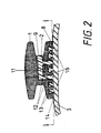
- Figure 2 shows the button 1 fully pressed with adhesive 2.
- the adhesive 2 fills the opening 9, the transverse channel 11, the riser holes 1 and the undercut ring channels 13 and thereby forms a positive connection with the button 1.
- the adhesive 2 is on the glass side entire adhesive surface 16, which is delimited by the edge 8, distributed and adheres to the glass cover 3 by adhesion.
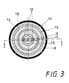
- Figure 3 shows the adhesive surface 16 of the button 1 along the line III-III in Figure 2.
- the adhesive passes through the opening 9, the transverse channel 11 and the riser holes 12 in one of the rear Schittenen ring channels 13 and distributed from there over the adhesive surface 16 and the further ring channels 13 to the edge 8.
- a sufficient number of ventilation slots 14, distributed over the edge 8, allows the air located between the adhesive surface 16 and the glass cover 3 to escape and thus a bubble-free adhesive surface 16, so that the space between the adhesive surface 16 and the glass lid 3 is completely filled with adhesive 2.
Landscapes
- Engineering & Computer Science (AREA)
- Mechanical Engineering (AREA)
- Food Science & Technology (AREA)
- Chemical & Material Sciences (AREA)
- Structural Engineering (AREA)
- Ceramic Engineering (AREA)
- Organic Chemistry (AREA)
- Adhesives Or Adhesive Processes (AREA)
- Table Devices Or Equipment (AREA)
- Ceramic Products (AREA)
- Cookers (AREA)
- Details Of Rigid Or Semi-Rigid Containers (AREA)
Abstract
Description
Die Erfindung betrifft ein Verfahren und eine Vorrichtung zum Ankleben eines Griffelementes an einem Geschirrteil.The invention relates to a method and a device for gluing a handle element to a piece of tableware.
Griffelemente wie Griffe, Knöpfe, Henkel, etc. bestehen in der Regel aus Kunststoff und werden meist mit Metall-Konstruktionsteilen wie Spannbändern, Scheiben und Schrauben an einem Geschirrteil befestigt.Handle elements such as handles, knobs, handles, etc. are usually made of plastic and are usually attached to a piece of tableware using metal construction parts such as straps, washers and screws.
Ist das Geschirrteil vornehmlich Töpfe, Pfannen, Deckel, Krüge, Kannen, etc. aus Glas, Glaskeramik, Keramik, Porzellan, glasiertem Ton oder ähnlichem, für die Verwendung im Mikrowellenherd bestimmt, so dürfen keine Metallteile für die Befestigung des Griffelements verwendet werden. Die Verbindung des Griffelementes mit dem Geschirrteil erfolgt dann vorzugsweise durch Ankleben. Der dafür verwendete Klebstoff muß den im Küchenbetrieb vorkommenden Anforderungen genügen:
- er muß sowohl mit dem Griffelement als auch mit dem Geschirrteil eine festhaftende Verbindung eingehen;
- er muß ausreichend elastisch sein, um die hohe Differenz der Ausdehnungskoeffizienten auszugleichen. So hat zum Beispiel Glas einen Ausdehnungskoeffizienten von 3,3 x 10⁻⁶/K und Kunststoff von 80 x 10⁻⁶/K;
- er muß temperaturbeständig bis ca. 280°C sein;
- er muß eine ausreichend hohe Zerreißfestigkeit aufweisen;
- er muß beständig gegen Säuren und Laugen sein;
- und er muß lebensmittelecht sein.If the crockery part is primarily pots, pans, lids, jugs, jugs, etc. made of glass, glass ceramic, ceramic, porcelain, glazed clay or the like, intended for use in the microwave oven, then no metal parts may be used to attach the handle element. The connection of the handle element to the crockery part is then preferably done by gluing. The adhesive used for this must meet the requirements in the kitchen:
- He must make a firm connection with both the handle element and the dishes;
- It must be sufficiently elastic to compensate for the large difference in expansion coefficients. For example, glass has an expansion coefficient of 3.3 x 10⁻⁶ / K and plastic has 80 x 10⁻⁶ / K;
- It must be temperature resistant up to approx. 280 ° C;
- It must have a sufficiently high tensile strength;
- it must be resistant to acids and bases;
- and it must be food safe.
Entsprechende Klebstoffe sind hochviskos und nicht fließfähig.Corresponding adhesives are highly viscous and not flowable.
Klebeverbindungen zwischen einem Krug aus Glas oder Keramik und einem Griff aus Kunststoff sind aus den DE-PS'en 30 48 783 und 31 09 759 bekannt. Dort wird eine definierte Klebstoffmenge auf den Griff oder den Krug aufgetragen und werden die beiden zu verklebenden Teile zusammengefügt. Der Klebstoff fließt hierbei durch Löcher im Griff und kann auf der der Klebestelle abgewandten Seite Verdickungen bilden, so daß dar Griff auch formschlüssig vom Klebstoff gehalten wird. Klebstoffe für solche Klebeverbindungen dürfen jedoch nicht hochviskos sein, da sonst die formschlüssige Verbindung am Griff nicht zustande kommt. Die beschriebenen Kunststoff-/Glasverklebungen sind außerdem nur bis ca. 100°C temperaturfest.Adhesive connections between a jug made of glass or ceramic and a handle made of plastic are known from DE-PS's 30 48 783 and 31 09 759. There, a defined amount of adhesive is applied to the handle or jug and the two parts to be glued are joined together. The adhesive flows through holes in the handle and can form thickenings on the side facing away from the adhesive point, so that the handle is also held positively by the adhesive. However, adhesives for such adhesive connections must not be highly viscous, since otherwise the positive connection on the handle will not be achieved. The plastic / glass bonds described are also only temperature-resistant up to approx. 100 ° C.
Der Erfindung liegt die Aufgabe zugrunde, ein Verfahren zum Ankleben eines Griffelementes an einem Geschirrteil zu schaffen, das die oben ausgeführten Bedingungen erfüllt und die Nachteile des Standes der Technik vermeidet.The invention has for its object to provide a method for gluing a handle element to a piece of crockery that meets the conditions outlined above and avoids the disadvantages of the prior art.
Nach der vorliegenden Erfindung wird diese Aufgabe gelöst mit einem Verfahren, bei dem ein Griffelement an die vorgesehene Anklebestelle eines Geschirrteils gepreßt und ein Klebstoff in das Griffelement gespritzt wird, wobei der Klebstoff durch mindestens einen Kanal an die Klebefläche des Griffelementes gelangt und sich dort zwichen Griffelement und Anklebestelle verteilt. Durch dieses Verfahren kann auch hochviskoser Klebstoff an die gesamte Klebefläche gebracht werden. Bei dieser Aufbringung des Kunststoffes durch Einspritzen unter Druck kann auch ein thixotropes Verhalten des Klebstoffes ausgenutzt werden, wobei der Klebstoff während des Einspritzens eine niedrige Viskosität annimmt und sich somit besser auf den Klebeflächen verteilt. Beim Auftragen des Klebstoffes wie im Stand der Technik beschrieben, kann das thixotrope Verhalten nicht oder nur ungenügend ausgenutzt werden.According to the present invention, this object is achieved with a method in which a grip element is pressed onto the intended attachment point of a tableware part and an adhesive is injected into the grip element, the adhesive reaching the adhesive surface of the grip element through at least one channel and passing between the grip element and glue point distributed. This procedure can also be used to apply highly viscous adhesive to the entire adhesive surface. In this application of the plastic by injection under pressure, a thixotropic behavior of the adhesive can also be exploited, the adhesive assuming a low viscosity during injection and thus being better distributed on the adhesive surfaces. At the Applying the adhesive as described in the prior art, the thixotropic behavior can not be used or only insufficiently.
Bei einem gewinkelten Verlauf des Kanals, durch den der Klebstoff gespritzt wird, erhält man nach Aushärtung des Klebstoffes eine formschlüssige Verbindung des Klebstoffes am Griffelement, wodurch auch mit an Kunststoffen weniger gut haftenden Klebstoffen ein dauerhafte und feste Verbindung des Klebstoffes am Griffelement erreicht wird. Zu dem selben Zweck können an der Klebefläche des Griffelementes eine oder mehrere hinterschnittene Rinnen eingelassen sein. Zusätzlich erhält man - auch bei nicht hinterschnittenen Rinnen - eine vergrößerte Kontaktfläche des Griffelementes zum Klebstoff und dadurch eine stabilere Klebeverbindung.If the channel is angled through which the adhesive is sprayed, a positive connection of the adhesive to the handle element is obtained after the adhesive has hardened, whereby a permanent and firm connection of the adhesive to the handle element is achieved even with adhesives that are less adhesive to plastics. For the same purpose, one or more undercut grooves can be embedded in the adhesive surface of the grip element. In addition, an enlarged contact surface of the grip element with the adhesive is obtained, even with channels that are not undercut, and thereby a more stable adhesive connection.
Im folgenden wird eine beispielhafte Ausführungsform anhand von Zeichnungen näher erläutert.An exemplary embodiment is explained in more detail below with reference to drawings.
Es zeigen:
Figur 1 Einspritzen eines Klebstoffes in einen Knopf;Figur 2 eine fertige Klebeverbindung des Knopfes auf einem Glasdeckel;Figur 3 Klebefläche des Knopfes.
- Figure 1 injecting an adhesive into a button;
- Figure 2 shows a finished adhesive connection of the button on a glass lid;
- Figure 3 adhesive surface of the button.
Figur 1 zeigt das erfindungsgemäße Verfahren anhand eines Knopfes 1, der mittels eines Klebstoffes 2 auf einem Glasdeckel 3 befestigt wird. Der Knopf 1 wird hierbei in einem Gegenhalter 4, der als Vakuumknopffutter ausgebildet ist, gehalten. Das Halten des Knopfes 1 am Gegenhalter 4 erfolgt durch Beaufschlagen des Innenraumes 5 im Gegenhalter 4 mit Unterdruck, wobei für rauhe Knopfoberflächen ein O-Ring 6 zur Abdichtung dient. Auf einem zweiten Gegenhalter 7 liegt der Glasdeckel 3. Dieser zweite Gegenhalter 7 ist so geformt, daß der Glasdeckel 3 beim Auflegen zentiert wird.FIG. 1 shows the method according to the invention using a
Die beiden Gegenhalter 4 und 7 werden in Pfeilrichtung gegeneinander gepreßt so daß der Knopf 1 mit seinem ringförmigen Rand 8 fest auf den Glasdeckel 3 gedrückt wird.The two
An eine sich nach außen konisch erweiternde Öffnung 9 des Knopfes wird in Pfeilrichtung eine Dosier-Klebstoffdüse 10 gedrückt und Klebstoff 2 durch diese Dosier-Klebstoffdüse 10 in einen Querkanal 11 gepreßt. Der Klebstoff 2 gelangt weiter über Steiglöcher 12 an den Glasdeckel 3 und wird weiter zwischen Glasdeckel 3 und Knopf 1 bis zum Rand 8 des Knopfes 1 gedrückt, wobei auch hinterschnittene Ringkanäle 13 mit dem Klebstoff 2 gefüllt werden. Die durch den Klebstoff 2 verdrängte Luft entweicht durch Entlüftungsschlitze 14, die in den Rand 8 eingelassen sind. Die Entlüftungsschlitze 14 weisen bei einer vorteilhaften Ausführungsform eine Höhe von ≦ 0,2 mm auf, so daß kein Klebstoff 2 durch sie gepreßt werden kann. Sobald sich kein Klebstoff 2 mehr in den Querkanal 11 pressen läßt, wird die Dosier-Klebstoffdüse 10 entgegen der Pfeilrichtung zurückgezogen und mittels eines Stempels 15 verschlossen. Der Verschließvorgang kann so gesteuert werden, daß die Öffnung 9 beim Zurückziehen der Dosier-Klebstoffdüse 10 noch mit Klebstoff 2 gefüllt wird, so daß ein glatter Verschluß der Öffnung 9 erreicht wird.A metering
Figur 2 zeigt den mit Klebstoff 2 vollgepreßten Knopf 1. Der Klebstoff 2 füllt die Öffnung 9, den Querkanal 11, die Steiglöcher 1 sowie die hinterschnittenen Ringkanäle 13 aus und bildet dadurch eine formschlüssige Verbindung mit dem Knopf 1. Glasseitig ist der Klebstoff 2 über die gesamte Klebefläche 16, die durch den Rand 8 begrenzt wird, verteilt und haftet am Glasdeckel 3 durch Adhäsion.Figure 2 shows the
Figur 3 zeigt die Klebefläche 16 des Knopfes 1 entlang der Linie III-III in Figur 2. Der Klebstoff gelangt durch die Öffnung 9, den Querkanal 11 und die Steiglöcher 12 in einen der hinter schittenen Ringkanäle 13 und verteilt sich von dort über die Klebefläche 16 und die weiteren Ringkanäle 13 bis zum Rand 8. Eine genügende Anzahl von Entlüftungsschlitzen 14, über den Rand 8 verteilt, ermöglicht ein Entweichen der sich zwischen der Klebefläche 16 und dem Glasdeckel 3 befindenden Luft und somit ein blasenfreie Klebefläche 16, so daß der Raum zwischen der Klebefläche 16 und dem Glasdeckel 3 vollständig mit Klebstoff 2 gefüllt wird.Figure 3 shows the
Bei Verwendung eines bis 280°C temperaturbeständigen Klebstoffes erhält man ein für Mikrowellenöfen und Backöfen geeignetes Geschirr.When using an adhesive that is temperature-resistant up to 280 ° C, one obtains dishes suitable for microwave ovens and ovens.
Claims (9)
Applications Claiming Priority (2)
| Application Number | Priority Date | Filing Date | Title |
|---|---|---|---|
| DE3826314 | 1988-08-03 | ||
| DE3826314A DE3826314C1 (en) | 1988-08-03 | 1988-08-03 |
Publications (2)
| Publication Number | Publication Date |
|---|---|
| EP0353510A1 true EP0353510A1 (en) | 1990-02-07 |
| EP0353510B1 EP0353510B1 (en) | 1992-09-16 |
Family
ID=6360127
Family Applications (1)
| Application Number | Title | Priority Date | Filing Date |
|---|---|---|---|
| EP89112803A Expired - Lifetime EP0353510B1 (en) | 1988-08-03 | 1989-07-13 | Handle and method for glueing the handel onto a piece of table ware |
Country Status (5)
| Country | Link |
|---|---|
| US (1) | US5056188A (en) |
| EP (1) | EP0353510B1 (en) |
| JP (1) | JPH0660063B2 (en) |
| KR (1) | KR930009438B1 (en) |
| DE (2) | DE3826314C1 (en) |
Cited By (4)
| Publication number | Priority date | Publication date | Assignee | Title |
|---|---|---|---|---|
| EP0931641A2 (en) * | 1998-01-22 | 1999-07-28 | HENNIGES ELASTOMER- UND KUNSTSTOFFTECHNIK GMBH & CO KG | Process for joining a construction part with a construction element |
| US6312475B1 (en) | 1996-10-31 | 2001-11-06 | Jerome P. Voisin | Prosthetic adaptor and prosthetic limb using same |
| EP2982490A1 (en) * | 2014-08-08 | 2016-02-10 | Senvion GmbH | Method for mounting a vortex generator and a mounting device for carrying out the method |
| US11548239B2 (en) * | 2016-09-12 | 2023-01-10 | Textron Innovations, Inc. | Bonding process and system |
Families Citing this family (14)
| Publication number | Priority date | Publication date | Assignee | Title |
|---|---|---|---|---|
| DE4345605B4 (en) * | 1993-09-17 | 2008-09-11 | Continental Teves Ag & Co. Ohg | Electromotor pump assembly - uses main and pump bearings to support forces in use, or supports rotor shaft on main bearing for testing |
| GB2310876B (en) * | 1996-03-04 | 1999-06-23 | Creda Ltd | Fixing a bracket onto a panel |
| DE19714385B4 (en) * | 1997-03-27 | 2009-04-23 | Swissbit Germany Gmbh | Method for fixing components in COB design |
| KR100490789B1 (en) * | 1997-07-21 | 2005-09-13 | 주식회사 휴비스 | Manufacturing method of ultra fine fiber |
| JPH11148452A (en) | 1997-09-11 | 1999-06-02 | Denso Corp | Ignition device for cylinder injection gasoline engine |
| DE19756922A1 (en) * | 1997-12-19 | 1999-04-08 | Braun Ag | Liquid container, e.g. coffee pot |
| ES2240046T3 (en) * | 2000-08-03 | 2005-10-16 | La Termoplastic F.B.M. S.R.L. | HANDLE OF TWO COMPONENTS, FOR COOKING CONTAINER, PARTICULARLY ADEQUATE TO BE USED AS COVER HANDLE. |
| DE10252151B4 (en) * | 2002-11-09 | 2006-03-23 | Daimlerchrysler Ag | Method for bonding two components |
| DE102006021079B4 (en) * | 2006-03-21 | 2008-01-17 | IMPRESS Metal Packaging S.A., Crosmières | Container with closure combination |
| CN100460452C (en) * | 2006-12-15 | 2009-02-11 | 清华大学 | Preparing process of antiseptic graft polymer in micron and nanometer composite structure |
| CN100460451C (en) * | 2006-12-15 | 2009-02-11 | 清华大学 | Process of optically grafting long fatty carbon chain quaternary ammonium salt to the surface of polymer |
| DE102010026037A1 (en) * | 2010-07-03 | 2012-01-05 | Bodo Sperling | Fixed adhesion of an adhesive agent with a glass surface and a silicone plastic or other plastic, and with other material |
| DE102013006471B4 (en) * | 2013-04-15 | 2023-11-16 | Wmf Gmbh | Pot lid with glued lid handle and method for producing a pot lid |
| CN112704344A (en) * | 2019-10-25 | 2021-04-27 | 王建平 | Adhesive handle |
Citations (2)
| Publication number | Priority date | Publication date | Assignee | Title |
|---|---|---|---|---|
| FR1526119A (en) * | 1966-04-05 | 1968-05-24 | Hilti Ag | Method and device for obtaining adhesive bond |
| DE3048783A1 (en) * | 1980-12-23 | 1982-07-08 | Bosch-Siemens Hausgeräte GmbH, 7000 Stuttgart | Handle fixture for electric coffee-maker - includes ventilation channels in mounting surface of handle to ensure optimum hardening of adhesive |
Family Cites Families (12)
| Publication number | Priority date | Publication date | Assignee | Title |
|---|---|---|---|---|
| DE1214112B (en) * | 1961-02-17 | 1966-04-07 | Wilhelm Koellner | Fastening ring made of spring steel for fixing parts on door handles, olives and the like. |
| US4019221A (en) * | 1976-03-15 | 1977-04-26 | Heinrich Baumgarten, Eisen- Und Blechwarenfabrik | Pan handle |
| SU894220A1 (en) * | 1978-11-01 | 1981-12-30 | Предприятие П/Я Х-5539 | Non-detachable connection |
| DE3109759A1 (en) * | 1981-03-13 | 1982-09-23 | Bosch-Siemens Hausgeräte GmbH, 7000 Stuttgart | BREW BEVERAGE JUG, IN PARTICULAR COFFEE JUG OF AN ELECTRIC COFFEE MAKER |
| JPS5826537U (en) * | 1981-08-12 | 1983-02-19 | 日本スチレンペ−パ−株式会社 | display board |
| ES275409Y (en) * | 1982-05-27 | 1985-03-16 | Bosch-Siemens Hausgerate Gmbh | A JUG FOR INFUSION DRINKS. |
| DE3245553C2 (en) * | 1982-12-09 | 1986-05-07 | Compakta Werke Baustoff-GmbH, 8225 Traunreut | Process for the permanent connection of structural parts |
| GB2133496B (en) * | 1982-12-21 | 1986-06-25 | Univ Surrey | Structural connections |
| DE3415120A1 (en) * | 1984-04-21 | 1985-10-31 | Braun Ag, 6000 Frankfurt | HOUSEHOLD VESSEL WITH GLUE HANDLE |
| JPS6365113U (en) * | 1986-10-16 | 1988-04-28 | ||
| US4812193A (en) * | 1986-12-22 | 1989-03-14 | Gauron Richard F | Inset panel fastener and method of using |
| US4837892A (en) * | 1988-03-04 | 1989-06-13 | Conair Corporation | Cushioned handle structure for personal care appliances |
-
1988
- 1988-08-03 DE DE3826314A patent/DE3826314C1/de not_active Expired - Lifetime
-
1989
- 1989-07-13 EP EP89112803A patent/EP0353510B1/en not_active Expired - Lifetime
- 1989-07-13 DE DE8989112803T patent/DE58902283D1/en not_active Expired - Fee Related
- 1989-07-21 KR KR1019890010364A patent/KR930009438B1/en not_active IP Right Cessation
- 1989-07-26 JP JP1191578A patent/JPH0660063B2/en not_active Expired - Lifetime
- 1989-08-02 US US07/388,465 patent/US5056188A/en not_active Expired - Fee Related
Patent Citations (2)
| Publication number | Priority date | Publication date | Assignee | Title |
|---|---|---|---|---|
| FR1526119A (en) * | 1966-04-05 | 1968-05-24 | Hilti Ag | Method and device for obtaining adhesive bond |
| DE3048783A1 (en) * | 1980-12-23 | 1982-07-08 | Bosch-Siemens Hausgeräte GmbH, 7000 Stuttgart | Handle fixture for electric coffee-maker - includes ventilation channels in mounting surface of handle to ensure optimum hardening of adhesive |
Cited By (6)
| Publication number | Priority date | Publication date | Assignee | Title |
|---|---|---|---|---|
| US6312475B1 (en) | 1996-10-31 | 2001-11-06 | Jerome P. Voisin | Prosthetic adaptor and prosthetic limb using same |
| EP0931641A2 (en) * | 1998-01-22 | 1999-07-28 | HENNIGES ELASTOMER- UND KUNSTSTOFFTECHNIK GMBH & CO KG | Process for joining a construction part with a construction element |
| EP0931641A3 (en) * | 1998-01-22 | 1999-10-13 | HENNIGES ELASTOMER- UND KUNSTSTOFFTECHNIK GMBH & CO KG | Process for joining a construction part with a construction element |
| EP2982490A1 (en) * | 2014-08-08 | 2016-02-10 | Senvion GmbH | Method for mounting a vortex generator and a mounting device for carrying out the method |
| US10000017B2 (en) | 2014-08-08 | 2018-06-19 | Senvion Gmbh | Method for mounting a vortex generator and mounting apparatus for carrying out the method |
| US11548239B2 (en) * | 2016-09-12 | 2023-01-10 | Textron Innovations, Inc. | Bonding process and system |
Also Published As
| Publication number | Publication date |
|---|---|
| JPH0660063B2 (en) | 1994-08-10 |
| DE3826314C1 (en) | 1990-03-29 |
| JPH0274573A (en) | 1990-03-14 |
| KR900003325A (en) | 1990-03-26 |
| DE58902283D1 (en) | 1992-10-22 |
| US5056188A (en) | 1991-10-15 |
| KR930009438B1 (en) | 1993-10-04 |
| EP0353510B1 (en) | 1992-09-16 |
Similar Documents
| Publication | Publication Date | Title |
|---|---|---|
| EP0353510A1 (en) | Handle and method for glueing the handel onto a piece of table ware | |
| DE3341194C2 (en) | Method for producing a hob, device for carrying out the method and hob produced by means of the device | |
| DE4325168C1 (en) | Prefabricated cooktop unit for glue-free installation in a frame construction or in a cutout | |
| DE19739580A1 (en) | Fixing handle to e.g. glass coffee pot | |
| DE2705568A1 (en) | Application of solder, e.g. to glass, ceramics or plastics substrate - by atomising or vapour deposition, giving thin, uniform, reproducible layer | |
| DE19703269A1 (en) | Hob and support frame system used to hold, seal and bond the frame to a cooker hob | |
| EP0285988A1 (en) | Baking mould | |
| DE3415120A1 (en) | HOUSEHOLD VESSEL WITH GLUE HANDLE | |
| EP0929712A1 (en) | Glass fiber fabric wallpaper | |
| DE4444546B4 (en) | Adhesive joint and method for polyethylene and polypropylene foams | |
| WO1997048319A1 (en) | Gripping combination system for fastening to glass or ceramic surfaces, method for the fastening and use thereof | |
| DE10250096B4 (en) | Method for connecting components and use of a connecting part for this purpose | |
| EP0514716A2 (en) | Glass ceramic cooking plate with a control panel. | |
| US5196153A (en) | Process and apparatus for securing a grip element to crockery or pottery | |
| DE19638232A1 (en) | Ceramic built-up part for dentistry | |
| DE3249574C2 (en) | Method for permanently connecting a handle to a glass jug | |
| DE2719128A1 (en) | Table leaf used for camping and in garden - has moisture-proof edge reinforcement injection moulded on at high temp. | |
| EP0900904A3 (en) | Hinge for container covers | |
| DE3048783A1 (en) | Handle fixture for electric coffee-maker - includes ventilation channels in mounting surface of handle to ensure optimum hardening of adhesive | |
| DE3305857C2 (en) | Method for attaching a plastic handle to a glass jug | |
| CH694752A5 (en) | Equipment for application of decorative item to tooth uses bedding - in material on surface or in surface cavity of tooth | |
| DE3911703C2 (en) | ||
| DE3501484A1 (en) | Process and device for producing a backing board covered with tiles | |
| DE102019202154A1 (en) | Door for a household appliance and household appliance | |
| CH697285B1 (en) | Inductive heating device for wok and processes for their preparation. |
Legal Events
| Date | Code | Title | Description |
|---|---|---|---|
| PUAI | Public reference made under article 153(3) epc to a published international application that has entered the european phase |
Free format text: ORIGINAL CODE: 0009012 |
|
| AK | Designated contracting states |
Kind code of ref document: A1 Designated state(s): CH DE FR GB IT LI NL SE |
|
| 17P | Request for examination filed |
Effective date: 19900226 |
|
| 17Q | First examination report despatched |
Effective date: 19910611 |
|
| GRAA | (expected) grant |
Free format text: ORIGINAL CODE: 0009210 |
|
| AK | Designated contracting states |
Kind code of ref document: B1 Designated state(s): CH DE FR GB IT LI NL SE |
|
| ET | Fr: translation filed | ||
| ITF | It: translation for a ep patent filed |
Owner name: STUDIO TORTA SOCIETA' SEMPLICE |
|
| REF | Corresponds to: |
Ref document number: 58902283 Country of ref document: DE Date of ref document: 19921022 |
|
| GBT | Gb: translation of ep patent filed (gb section 77(6)(a)/1977) | ||
| PLBE | No opposition filed within time limit |
Free format text: ORIGINAL CODE: 0009261 |
|
| STAA | Information on the status of an ep patent application or granted ep patent |
Free format text: STATUS: NO OPPOSITION FILED WITHIN TIME LIMIT |
|
| 26N | No opposition filed | ||
| EAL | Se: european patent in force in sweden |
Ref document number: 89112803.5 |
|
| PGFP | Annual fee paid to national office [announced via postgrant information from national office to epo] |
Ref country code: GB Payment date: 19980612 Year of fee payment: 10 |
|
| PGFP | Annual fee paid to national office [announced via postgrant information from national office to epo] |
Ref country code: SE Payment date: 19980624 Year of fee payment: 10 |
|
| PGFP | Annual fee paid to national office [announced via postgrant information from national office to epo] |
Ref country code: NL Payment date: 19980629 Year of fee payment: 10 Ref country code: FR Payment date: 19980629 Year of fee payment: 10 |
|
| PGFP | Annual fee paid to national office [announced via postgrant information from national office to epo] |
Ref country code: DE Payment date: 19980630 Year of fee payment: 10 |
|
| PGFP | Annual fee paid to national office [announced via postgrant information from national office to epo] |
Ref country code: CH Payment date: 19980701 Year of fee payment: 10 |
|
| PG25 | Lapsed in a contracting state [announced via postgrant information from national office to epo] |
Ref country code: GB Free format text: LAPSE BECAUSE OF NON-PAYMENT OF DUE FEES Effective date: 19990713 |
|
| PG25 | Lapsed in a contracting state [announced via postgrant information from national office to epo] |
Ref country code: SE Free format text: THE PATENT HAS BEEN ANNULLED BY A DECISION OF A NATIONAL AUTHORITY Effective date: 19990730 |
|
| PG25 | Lapsed in a contracting state [announced via postgrant information from national office to epo] |
Ref country code: LI Free format text: LAPSE BECAUSE OF NON-PAYMENT OF DUE FEES Effective date: 19990731 Ref country code: FR Free format text: THE PATENT HAS BEEN ANNULLED BY A DECISION OF A NATIONAL AUTHORITY Effective date: 19990731 Ref country code: CH Free format text: LAPSE BECAUSE OF NON-PAYMENT OF DUE FEES Effective date: 19990731 |
|
| PG25 | Lapsed in a contracting state [announced via postgrant information from national office to epo] |
Ref country code: NL Free format text: LAPSE BECAUSE OF NON-PAYMENT OF DUE FEES Effective date: 20000201 |
|
| GBPC | Gb: european patent ceased through non-payment of renewal fee |
Effective date: 19990713 |
|
| REG | Reference to a national code |
Ref country code: CH Ref legal event code: PL |
|
| EUG | Se: european patent has lapsed |
Ref document number: 89112803.5 |
|
| NLV4 | Nl: lapsed or anulled due to non-payment of the annual fee |
Effective date: 20000201 |
|
| PG25 | Lapsed in a contracting state [announced via postgrant information from national office to epo] |
Ref country code: DE Free format text: LAPSE BECAUSE OF NON-PAYMENT OF DUE FEES Effective date: 20000503 |
|
| REG | Reference to a national code |
Ref country code: FR Ref legal event code: ST |
|
| PG25 | Lapsed in a contracting state [announced via postgrant information from national office to epo] |
Ref country code: IT Free format text: LAPSE BECAUSE OF NON-PAYMENT OF DUE FEES;WARNING: LAPSES OF ITALIAN PATENTS WITH EFFECTIVE DATE BEFORE 2007 MAY HAVE OCCURRED AT ANY TIME BEFORE 2007. THE CORRECT EFFECTIVE DATE MAY BE DIFFERENT FROM THE ONE RECORDED. Effective date: 20050713 |