EP0353488B1 - Cockpit, insbesondere für einen Hubschrauber - Google Patents
Cockpit, insbesondere für einen Hubschrauber Download PDFInfo
- Publication number
- EP0353488B1 EP0353488B1 EP89112342A EP89112342A EP0353488B1 EP 0353488 B1 EP0353488 B1 EP 0353488B1 EP 89112342 A EP89112342 A EP 89112342A EP 89112342 A EP89112342 A EP 89112342A EP 0353488 B1 EP0353488 B1 EP 0353488B1
- Authority
- EP
- European Patent Office
- Prior art keywords
- cockpit
- support
- profile
- profile structure
- integral
- Prior art date
- Legal status (The legal status is an assumption and is not a legal conclusion. Google has not performed a legal analysis and makes no representation as to the accuracy of the status listed.)
- Expired - Lifetime
Links
- 238000000465 moulding Methods 0.000 claims description 18
- 239000002131 composite material Substances 0.000 claims description 12
- 239000002184 metal Substances 0.000 claims description 6
- 239000000463 material Substances 0.000 claims description 4
- 239000006261 foam material Substances 0.000 claims 1
- 239000000835 fiber Substances 0.000 description 10
- 238000004519 manufacturing process Methods 0.000 description 8
- 238000005253 cladding Methods 0.000 description 7
- 238000009434 installation Methods 0.000 description 6
- 238000010276 construction Methods 0.000 description 5
- 239000006260 foam Substances 0.000 description 2
- 238000009415 formwork Methods 0.000 description 2
- 238000009416 shuttering Methods 0.000 description 2
- 239000003351 stiffener Substances 0.000 description 2
- 230000015572 biosynthetic process Effects 0.000 description 1
- 238000000034 method Methods 0.000 description 1
- 230000003068 static effect Effects 0.000 description 1
- 206010048828 underweight Diseases 0.000 description 1
Images
Classifications
-
- B—PERFORMING OPERATIONS; TRANSPORTING
- B64—AIRCRAFT; AVIATION; COSMONAUTICS
- B64C—AEROPLANES; HELICOPTERS
- B64C27/00—Rotorcraft; Rotors peculiar thereto
- B64C27/04—Helicopters
-
- B—PERFORMING OPERATIONS; TRANSPORTING
- B64—AIRCRAFT; AVIATION; COSMONAUTICS
- B64C—AEROPLANES; HELICOPTERS
- B64C1/00—Fuselages; Constructional features common to fuselages, wings, stabilising surfaces or the like
Definitions
- the invention relates to a cockpit, in particular for a helicopter, according to the preamble of patent claim 1.
- a cockpit structure which consists of a more or less closed self-supporting outer shell which forms the supporting structure of the cockpit.
- Such a cockpit shell construction which is adapted to aerodynamic, but not other, in particular punctiform loads and inevitably only allows relatively small window and door cutouts, which in most cases still have to be provided with additional stiffeners in order to avoid inadmissible local stress concentrations the invention.
- the supporting cockpit structure consists of a supporting structure, which is adapted to the attacking static and dynamic loads in the manner of a truss, the stiffly connected framework parts of which are made of lightweight metal hollow profiles for reasons of weight, an economical one Manufacturing of the scaffolding taking into account the relatively limited number of aircraft is achieved in that the individual scaffolding parts are prefabricated separately from each other and then assembled, for example welded, to form the finished scaffolding.
- the resulting manufacturing tolerances are compensated for when installing the cockpit windshields and doors, for which a high degree of fit is required, especially in helicopter construction, whereby the installation effort required for this with regard to the cost and weight advantages otherwise achieved with this manufacturing method is taken.
- the object of the invention is to design the cockpit of the type mentioned at the outset in such a way that, while maintaining a weight-saving design, the total outlay is reduced, also taking into account the number of pieces customary for aircraft.
- the claimed design of the scaffolding parts encompassing at least one cockpit door cutout as a support profile structure made of fiber composite material or superplastically deformed metal, which is produced integrally in a molding tool, not only reduces the construction weight of the cockpit, because separate, weight-increasing stiffeners or connections, such as screw or rivet connections between the individual members
- the additional effort caused by the integral design is more than compensated for even with relatively small cockpit quantities by the fact that the otherwise time-consuming fitting work for the installation of the cockpit doors and preferably also windows is not just for the initial installation, but also cease to apply in the event of a later renewal.
- the invention thus enables a tailor-made design of the support structure in the area of the cockpit cutouts and thereby a full interchangeability of the doors (and windows) even from a cost perspective and even for the usual small series production.
- the integral support profile structure has a hollow profile cross-section with regard to an optimal use of strength and weight saving according to claim 2, namely according to claim 3 preferably in the form of a closed hollow profile.
- the hollow profile interior is expediently filled with a honeycomb, foam or pressure hose support core.
- a honeycomb, foam or pressure hose support core it is also according to claim 5 It is possible to insert prefabricated, dimensionally stable partial profile elements from the same material as the supporting profile structure to be produced, which, while keeping the hollow profile interior free, together with the material molded on the molding surfaces of the molding tool (fiber composite material or superplastically deformed metal) harden to form the integral cockpit structure are, which on the one hand eliminates the manufacturing and - albeit low - weight for an inner hollow profile support core and on the other hand, a relatively simple molding tool is sufficient even for an integral support profile structure with a complicated hollow profile cross-sectional profile.
- the outer lining of the cockpit is molded and hardened simultaneously and together with the supporting profile structure in the molding tool for manufacturing reasons, and furthermore the supporting profile structure according to claim 7 comprises at least two cockpit cutouts including the door cutout.
- the advantages of the design according to the invention are particularly evident in a helicopter cockpit with a support post arranged between two front window cutouts of the cockpit in the center plane of the cockpit.
- a cockpit of this type is composed according to claim 8 from two cockpit halves which are mirror-symmetrical to the center plane of the cockpit and each formed as an integral support profile structure.
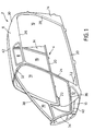
- the cockpit 2 shown in Fig. 1 which is attached on the back to the center fuselage and on the underside to the bottom shell (both not shown) of a helicopter, contains as main components a support frame that is dimensionally stable with respect to the operating loads, generally designated 4, and an integral molded on the supporting frame parts, which consists of a roof cladding 6, which is provided with recesses 8 for the skylights, as well as a floor cladding 10 adjoining the base shell of the helicopter, which is provided with recesses 12 for the bow window, and side cladding parts 14 on the rear Cockpit end exists.
- a support frame that is dimensionally stable with respect to the operating loads
- an integral molded on the supporting frame parts which consists of a roof cladding 6, which is provided with recesses 8 for the skylights, as well as a floor cladding 10 adjoining the base shell of the helicopter, which is provided with recesses 12 for the bow window, and side cladding parts 14 on the rear Cockpit end exists.
- the support structure 4 is formed from fiber composite hollow profiles which limit the door cutouts 16 and the front window cutouts 18 of the cockpit 2 with a high degree of accuracy, thereby ensuring that the doors and front windows are fully interchangeable.
- the cockpit is composed of two mirror-symmetrical cockpit halves 2A and 2B, each of which is designed as an integral hollow profile structure 4A and 4B, including the associated casing parts.
- each hollow profile structure 4A or 4B consists of a lower door frame 20, which is provided at the front end with an integrally molded support bracket 22 for fastening the cockpit 2 to the helicopter base shell, an adjoining door jamb 24, which at the same time provides the lateral edge limitation for the windshield forms an upper and a rear, folding door frame 26 and 28, to which a rear roof frame 30 for attachment to the helicopter center fuselage and a front roof frame 32, which forms the upper front window boundary, are connected, and a semi-annular bow frame part 34 which is integrally connected to the door jamb 24 via a side frame 36 and together with this and a central mullion part 38 extending from the bow frame part 34 via the front to the rear roof frame 32, 30 limits the front window cutout 18 of the supporting structure 4A or 4B.
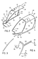
- the two cockpit halves 2A and 2B are joined together by a connecting strip 40 along the floor covering parts 10 and by a connecting flap 42 (FIG. 3) which is glued and / or riveted to the central post parts 38 over the entire length, the two bow frame parts 34 together form the front ring frame for the bow cap of the cockpit and the two middle post parts 38, which form the middle post which extends from the ring frame to the rear cockpit end and separates the two front windows of the cockpit.
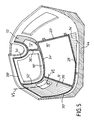
- the above-mentioned scaffolding parts of the two integral supporting profile structures 4A and 4B are each designed as hollow sections closed in cross section with a cross-sectional configuration that changes depending on the function of the respective hollow profile part and are formed together with the casing parts in a molding tool 44 (FIG. 5) to form a monolithic cockpit half and cured, FIG. 5 showing the mold 44 for the right cockpit half 2B.
- the individual, integrally interconnected hollow profile parts of the supporting structure 4B are molded and hardened on the correspondingly, but with a comma, cross-hatched surface areas of the molding surface of the molding tool 44, the inner contour of which corresponds to the outer contour of the cockpit half to be produced, while for the integral Forming parts molded onto the supporting structure, which are hatched longitudinally in FIG. 5 but are also correspondingly, but with a comma, designated areas of the mold 44.
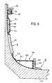
- the molding tool 44 is completed by shaped pieces 46, 48, 50 according to FIG. 6, which are not shown in FIG Form hollow profile or formwork parts.
- the manufacturing method of the integral structure is explained in detail on the basis of the partial section shown in FIG. 6:
- the rectangular hollow profile of the central post part 38 is produced by means of a foam support core 52 which is wrapped with the fiber composite laminate.
- a shaped part 46 fastened to the mold 44 is used to limit the edge of the hollow profile 38, the recess on the hollow profile 38 required for the flush installation of the connecting lug 42 being achieved by the T-shaped design of the shaped part 46.
- the roof cladding 6 is then integrally formed on the hollow profile 38.
- a sandwich construction is selected, as shown in the upper part of FIG. 6 for the roof cladding section 6.1.
- a honeycomb core 54 in the simplest case made of paper, is laminated between an upper and a lower fiber composite layer 56, 58.
- shaped pieces such as shaped piece 48 for the roof window cutout 8 according to FIG. 6, are in turn attached to the molding tool 44.
- the recess required for flush installation of the window panes is achieved on the window recesses.
- Such a preformed fiber composite profile element 60 is shown in the form of a three-armed, one-piece component in FIG. 4, together with the Associated profile cross-sections, which are formed on the one hand by the preformed profile element and on the other hand by the fiber composite laminate which is fully cured at the same time and is applied to the mold surfaces of the molding tool (shown in broken lines in FIG. 4).
- the integral supporting structure structure which surrounds the front window cutout 18 has a recessed profile web 64, in a manner corresponding to the window recesses of the casing parts, through an installation or replacement of the front window flush with the outer skin (dash-dotted in Fig. 4 drawn) is made considerably easier without laborious fitting work.
- the fiber composite material is enclosed in a vacuum film - shown in dashed lines in FIG. 6 - and then cured in an autoclave under the action of pressure and heat, the molding space present between molding tool 44 and vacuum film being at least at the beginning of the Curing process is evacuated.
- the entire cockpit half is finished as an integral fiber composite structure with high accuracy.
- the second cockpit half 2A is also produced in a corresponding manner, and both cockpit halves are then assembled in the manner described above and allow the front windows and cockpit doors to be fully interchangeable.
- the two halves of the cockpit can be manufactured with the same manufacturing method and construction - apart from material-specific differences - if desired also from superplastic deformed metal as integral structural units.
Landscapes
- Engineering & Computer Science (AREA)
- Mechanical Engineering (AREA)
- Aviation & Aerospace Engineering (AREA)
- Moulding By Coating Moulds (AREA)
- Securing Of Glass Panes Or The Like (AREA)
- Golf Clubs (AREA)
- Laminated Bodies (AREA)
Applications Claiming Priority (2)
| Application Number | Priority Date | Filing Date | Title |
|---|---|---|---|
| DE3826636 | 1988-08-05 | ||
| DE3826636A DE3826636A1 (de) | 1988-08-05 | 1988-08-05 | Cockpit, insbesondere fuer einen hubschrauber |
Publications (3)
| Publication Number | Publication Date |
|---|---|
| EP0353488A2 EP0353488A2 (de) | 1990-02-07 |
| EP0353488A3 EP0353488A3 (en) | 1990-11-14 |
| EP0353488B1 true EP0353488B1 (de) | 1993-10-13 |
Family
ID=6360303
Family Applications (1)
| Application Number | Title | Priority Date | Filing Date |
|---|---|---|---|
| EP89112342A Expired - Lifetime EP0353488B1 (de) | 1988-08-05 | 1989-07-06 | Cockpit, insbesondere für einen Hubschrauber |
Country Status (4)
| Country | Link |
|---|---|
| US (1) | US5037041A (enExample) |
| EP (1) | EP0353488B1 (enExample) |
| DE (2) | DE3826636A1 (enExample) |
| ES (1) | ES2047066T3 (enExample) |
Families Citing this family (19)
| Publication number | Priority date | Publication date | Assignee | Title |
|---|---|---|---|---|
| US5609312A (en) * | 1991-09-30 | 1997-03-11 | Arlton; Paul E. | Model helicopter |
| FR2693976B1 (fr) * | 1992-07-22 | 1994-09-30 | Eurocopter France | Structure de fuselage pour hélicoptère. |
| DE4423642C1 (de) * | 1994-07-06 | 1995-10-12 | Daimler Benz Aerospace Ag | Tragrahmen, insbesondere für ein Kraftfahrzeug |
| FR2905669B1 (fr) * | 2006-09-13 | 2009-04-10 | Airbus France Sa | Encadrement pour pare-brise et procede de fabrication d'un encadrement pour pare-brise |
| EP2107001A1 (de) | 2008-04-04 | 2009-10-07 | Sika Technology AG | Verfahren zum Herstellen eines Hubschrauber-Cockpits |
| US8377248B2 (en) | 2010-06-16 | 2013-02-19 | Spirit Aerosystems, Inc. | Method and system for forming a complex monolithic thermoset part |
| AU2012267260B2 (en) * | 2011-06-07 | 2017-03-30 | Innova Helicopters Technology Holdings Nz Limited | A helicopter |
| USD678172S1 (en) * | 2012-02-10 | 2013-03-19 | Bell Helicopter Textron Inc. | Helicopter front windshields |
| US20130206908A1 (en) * | 2012-02-10 | 2013-08-15 | Bell Helicopter Textron Inc. | Rotorcraft Front Windshield |
| ITMO20130082A1 (it) * | 2013-03-29 | 2014-09-30 | Konner S R L | Struttura per aeromobili |
| EP2979975B1 (en) | 2014-07-30 | 2017-09-27 | AIRBUS HELICOPTERS DEUTSCHLAND GmbH | An aircraft with a framework structure that comprises at least one hollow frame. |
| USD871290S1 (en) | 2014-10-13 | 2019-12-31 | Gulfstream Aerospace Corporation | Flight deck with surface ornamentation |
| USD864811S1 (en) * | 2014-10-13 | 2019-10-29 | Gulfstream Aerospace Corporation | Set of window shades and visor rails for aircraft cockpit |
| RU2692367C2 (ru) | 2014-10-24 | 2019-06-24 | Юнайтед Текнолоджиз Корпорэйшн | Полимер с улучшенными характеристиками и способ его получения |
| CH710657A1 (de) * | 2015-01-28 | 2016-07-29 | Marenco Swisshelicopter Ag | Hubschrauberkabine. |
| CN106697252A (zh) * | 2015-11-17 | 2017-05-24 | 珠海航太科技有限公司 | 一种轻型飞机的座舱框架 |
| CN106477067B (zh) * | 2016-11-29 | 2019-05-28 | 中国直升机设计研究所 | 一种直升机机头外形设计方法 |
| EP3378788B1 (en) | 2017-03-22 | 2021-04-28 | AIRBUS HELICOPTERS DEUTSCHLAND GmbH | An aircraft with a fuselage that comprises at least one hollow beam element |
| PL234265B1 (pl) * | 2017-12-13 | 2020-01-31 | Flaris Spolka Z Ograniczona Odpowiedzialnoscia | Kompozytowa struktura wytrzymałościowa kabiny samolotu usztywniona ramą przestrzenną |
Family Cites Families (12)
| Publication number | Priority date | Publication date | Assignee | Title |
|---|---|---|---|---|
| FR1296103A (fr) * | 1961-05-06 | 1962-06-15 | Renault | Pièces de carrosserie métallo-plastiques |
| FR2202809A1 (en) * | 1972-10-17 | 1974-05-10 | Aerospatiale | Light aircraft sandwich structure - coated with resin impregnated reinforcing fabric |
| FR2292623A1 (fr) * | 1974-11-26 | 1976-06-25 | Aerospatiale | Procede pour la realisation de structures composites resistantes, notamment pour aerodynes et structures ainsi obtenues |
| DE2642523A1 (de) * | 1976-09-22 | 1978-03-23 | Burkhart Dipl Ing Grob | Verfahren und vorrichtung zur herstellung eines flugzeugbauteils in profilverstaerkter schalenbauweise |
| US4113910A (en) * | 1977-04-27 | 1978-09-12 | Rockwell International Corporation | Composite load coupler for reinforcing composite structural joints |
| US4304376A (en) * | 1977-12-05 | 1981-12-08 | The Boeing Company | Composite honeycomb core structures and single stage hot bonding method of producing such structures |
| US4294419A (en) * | 1979-01-22 | 1981-10-13 | Vought Corporation | Airframe assembly and process |
| GB2105633B (en) * | 1981-08-28 | 1985-07-31 | Dowty Rotol Ltd | Foam-containing structures |
| DE3401189A1 (de) * | 1983-01-25 | 1984-07-26 | Westland PLC, Yeovil, Somerset | Verbund-hubschrauberrumpf |
| DE3438602A1 (de) * | 1984-10-20 | 1986-04-24 | Robbe Modellsport Gmbh, 6424 Grebenhain | Verfahren zur herstellung eines modellteiles sowie nach diesem verfahren hergestelltes modellteil |
| US4863771A (en) * | 1985-08-22 | 1989-09-05 | The Budd Company | Hollow fiber reinforced structure and method of making same |
| US4867922A (en) * | 1986-12-29 | 1989-09-19 | Ford Motor Company | Method of making styling models |
-
1988
- 1988-08-05 DE DE3826636A patent/DE3826636A1/de active Granted
-
1989
- 1989-07-06 ES ES89112342T patent/ES2047066T3/es not_active Expired - Lifetime
- 1989-07-06 DE DE89112342T patent/DE58905892D1/de not_active Expired - Lifetime
- 1989-07-06 EP EP89112342A patent/EP0353488B1/de not_active Expired - Lifetime
- 1989-08-03 US US07/389,427 patent/US5037041A/en not_active Expired - Lifetime
Also Published As
| Publication number | Publication date |
|---|---|
| DE3826636A1 (de) | 1990-02-08 |
| EP0353488A3 (en) | 1990-11-14 |
| DE3826636C2 (enExample) | 1991-12-12 |
| ES2047066T3 (es) | 1994-02-16 |
| EP0353488A2 (de) | 1990-02-07 |
| US5037041A (en) | 1991-08-06 |
| DE58905892D1 (de) | 1993-11-18 |
Similar Documents
| Publication | Publication Date | Title |
|---|---|---|
| EP0353488B1 (de) | Cockpit, insbesondere für einen Hubschrauber | |
| EP0369134B1 (de) | Fahrzeugzelle | |
| DE2738895C2 (enExample) | ||
| EP2265485B1 (de) | Leichtbauteil für eine fahrzeugkarosserie | |
| DE102014106743B4 (de) | Strömungskörper mit einem darin integrierten Lasteinleitungselement, Verfahren zum Herstellen eines Strömungskörpers und Flugzeug mit einem solchen Strömungskörper | |
| DE1116538B (de) | Verfahren zur Herstellung eines Tragfluegels, insbesondere eines Drehfluegels, aus Kunststoff | |
| DE2808120A1 (de) | Rotorblatt und verfahren zu dessen herstellung | |
| EP0299005B1 (de) | Tragstab für einen webschaft | |
| DE2845708A1 (de) | Verfahren zum herstellen einer kraftfahrzeugkarosserie, sowie nach dem verfahren hergestellte kraftfahrzeugkarosserie | |
| EP1393893B1 (de) | Leichtbaustruktur aus metallischen Schichtwerkstoffen | |
| DE19751277C2 (de) | Fenster, Türe oder dergl. | |
| DE19649526C2 (de) | Fahrzeugkopf eines Eisenbahnfahrzeugs mit einer Führerkabine | |
| EP1245775A2 (de) | Kunststoffprofil | |
| EP1340640A1 (de) | Türrohbau für eine Kraftfahrzeugtür, Profilrahmen für einen Türrohbau und Verfahren zur Herstellung eines Profilrahmens für einen Türrohbau | |
| EP0964807A1 (de) | Rahmen zum befestigen von flächenelementen | |
| DE102008021224A1 (de) | Türflügel für ein Schienenfahrzeug | |
| EP0855978B1 (de) | Modulelement und herstellungsverfahren | |
| DE4417889B4 (de) | Flugzeugkörper sowie Verfahren zu dessen Herstellung | |
| EP1160147A2 (de) | Hohlträger für eine Kraftfahrzeugkarosserie | |
| DE4032171C2 (de) | Fensterrahmenbefestigung für Kraftfahrzeugtüren | |
| DE3515323C1 (de) | Unterstruktur fuer Trag- und Leitwerke von Flugzeugen | |
| DE10212452A1 (de) | Verfahren zur Herstellung eines wärmedämmenden Isolier- und Verbindungssteges und nach diesem Verfahren hergestellter Isolier- und Verbindungssteg | |
| DE102009048748B4 (de) | Verbindungsanordnung für Sandwichschalenelemente eines Luftfahrzeugs | |
| DE102005030939A1 (de) | Verfahren zur Herstellung eines im Wesentlichen schalenförmigen Bauteils | |
| EP1011963A1 (de) | Verfahren zum herstellen von ausschnitten in faserverbund-sandwichstrukturen und dadurch hergestellter ausschnitt |
Legal Events
| Date | Code | Title | Description |
|---|---|---|---|
| PUAI | Public reference made under article 153(3) epc to a published international application that has entered the european phase |
Free format text: ORIGINAL CODE: 0009012 |
|
| AK | Designated contracting states |
Kind code of ref document: A2 Designated state(s): DE ES FR GB IT NL |
|
| PUAL | Search report despatched |
Free format text: ORIGINAL CODE: 0009013 |
|
| AK | Designated contracting states |
Kind code of ref document: A3 Designated state(s): DE ES FR GB IT NL |
|
| 17P | Request for examination filed |
Effective date: 19901009 |
|
| 17Q | First examination report despatched |
Effective date: 19920416 |
|
| RAP1 | Party data changed (applicant data changed or rights of an application transferred) |
Owner name: EUROCOPTER DEUTSCHLAND GESELLSCHAFT MIT BESCHRAENK |
|
| GRAA | (expected) grant |
Free format text: ORIGINAL CODE: 0009210 |
|
| AK | Designated contracting states |
Kind code of ref document: B1 Designated state(s): DE ES FR GB IT NL |
|
| REF | Corresponds to: |
Ref document number: 58905892 Country of ref document: DE Date of ref document: 19931118 |
|
| ET | Fr: translation filed | ||
| GBT | Gb: translation of ep patent filed (gb section 77(6)(a)/1977) |
Effective date: 19931118 |
|
| ITF | It: translation for a ep patent filed | ||
| REG | Reference to a national code |
Ref country code: ES Ref legal event code: FG2A Ref document number: 2047066 Country of ref document: ES Kind code of ref document: T3 |
|
| PLBE | No opposition filed within time limit |
Free format text: ORIGINAL CODE: 0009261 |
|
| STAA | Information on the status of an ep patent application or granted ep patent |
Free format text: STATUS: NO OPPOSITION FILED WITHIN TIME LIMIT |
|
| 26N | No opposition filed | ||
| PGFP | Annual fee paid to national office [announced via postgrant information from national office to epo] |
Ref country code: GB Payment date: 20010614 Year of fee payment: 13 |
|
| PGFP | Annual fee paid to national office [announced via postgrant information from national office to epo] |
Ref country code: ES Payment date: 20010716 Year of fee payment: 13 |
|
| PGFP | Annual fee paid to national office [announced via postgrant information from national office to epo] |
Ref country code: NL Payment date: 20010717 Year of fee payment: 13 |
|
| REG | Reference to a national code |
Ref country code: GB Ref legal event code: IF02 |
|
| PG25 | Lapsed in a contracting state [announced via postgrant information from national office to epo] |
Ref country code: GB Free format text: LAPSE BECAUSE OF NON-PAYMENT OF DUE FEES Effective date: 20020706 |
|
| PG25 | Lapsed in a contracting state [announced via postgrant information from national office to epo] |
Ref country code: ES Free format text: LAPSE BECAUSE OF NON-PAYMENT OF DUE FEES Effective date: 20020707 |
|
| PG25 | Lapsed in a contracting state [announced via postgrant information from national office to epo] |
Ref country code: NL Free format text: LAPSE BECAUSE OF NON-PAYMENT OF DUE FEES Effective date: 20030201 |
|
| GBPC | Gb: european patent ceased through non-payment of renewal fee |
Effective date: 20020706 |
|
| NLV4 | Nl: lapsed or anulled due to non-payment of the annual fee |
Effective date: 20030201 |
|
| REG | Reference to a national code |
Ref country code: ES Ref legal event code: FD2A Effective date: 20030811 |
|
| PGFP | Annual fee paid to national office [announced via postgrant information from national office to epo] |
Ref country code: DE Payment date: 20080722 Year of fee payment: 20 |
|
| PGFP | Annual fee paid to national office [announced via postgrant information from national office to epo] |
Ref country code: IT Payment date: 20080726 Year of fee payment: 20 Ref country code: FR Payment date: 20080715 Year of fee payment: 20 |