EP0351689B1 - Palier à articulation, en particulier pour un guide d'essieu de véhicule automobile - Google Patents
Palier à articulation, en particulier pour un guide d'essieu de véhicule automobile Download PDFInfo
- Publication number
- EP0351689B1 EP0351689B1 EP89112616A EP89112616A EP0351689B1 EP 0351689 B1 EP0351689 B1 EP 0351689B1 EP 89112616 A EP89112616 A EP 89112616A EP 89112616 A EP89112616 A EP 89112616A EP 0351689 B1 EP0351689 B1 EP 0351689B1
- Authority
- EP
- European Patent Office
- Prior art keywords
- bearing
- rubber
- rings
- thickening
- compression
- Prior art date
- Legal status (The legal status is an assumption and is not a legal conclusion. Google has not performed a legal analysis and makes no representation as to the accuracy of the status listed.)
- Expired - Lifetime
Links
Images
Classifications
-
- B—PERFORMING OPERATIONS; TRANSPORTING
- B60—VEHICLES IN GENERAL
- B60G—VEHICLE SUSPENSION ARRANGEMENTS
- B60G7/00—Pivoted suspension arms; Accessories thereof
- B60G7/005—Ball joints
-
- F—MECHANICAL ENGINEERING; LIGHTING; HEATING; WEAPONS; BLASTING
- F16—ENGINEERING ELEMENTS AND UNITS; GENERAL MEASURES FOR PRODUCING AND MAINTAINING EFFECTIVE FUNCTIONING OF MACHINES OR INSTALLATIONS; THERMAL INSULATION IN GENERAL
- F16C—SHAFTS; FLEXIBLE SHAFTS; ELEMENTS OR CRANKSHAFT MECHANISMS; ROTARY BODIES OTHER THAN GEARING ELEMENTS; BEARINGS
- F16C11/00—Pivots; Pivotal connections
- F16C11/04—Pivotal connections
- F16C11/06—Ball-joints; Other joints having more than one degree of angular freedom, i.e. universal joints
- F16C11/08—Ball-joints; Other joints having more than one degree of angular freedom, i.e. universal joints with resilient bearings
- F16C11/083—Ball-joints; Other joints having more than one degree of angular freedom, i.e. universal joints with resilient bearings by means of parts of rubber or like materials
-
- F—MECHANICAL ENGINEERING; LIGHTING; HEATING; WEAPONS; BLASTING
- F16—ENGINEERING ELEMENTS AND UNITS; GENERAL MEASURES FOR PRODUCING AND MAINTAINING EFFECTIVE FUNCTIONING OF MACHINES OR INSTALLATIONS; THERMAL INSULATION IN GENERAL
- F16F—SPRINGS; SHOCK-ABSORBERS; MEANS FOR DAMPING VIBRATION
- F16F1/00—Springs
- F16F1/36—Springs made of rubber or other material having high internal friction, e.g. thermoplastic elastomers
- F16F1/38—Springs made of rubber or other material having high internal friction, e.g. thermoplastic elastomers with a sleeve of elastic material between a rigid outer sleeve and a rigid inner sleeve or pin, i.e. bushing-type
- F16F1/393—Springs made of rubber or other material having high internal friction, e.g. thermoplastic elastomers with a sleeve of elastic material between a rigid outer sleeve and a rigid inner sleeve or pin, i.e. bushing-type with spherical or conical sleeves
-
- B—PERFORMING OPERATIONS; TRANSPORTING
- B60—VEHICLES IN GENERAL
- B60G—VEHICLE SUSPENSION ARRANGEMENTS
- B60G2204/00—Indexing codes related to suspensions per se or to auxiliary parts
- B60G2204/40—Auxiliary suspension parts; Adjustment of suspensions
- B60G2204/416—Ball or spherical joints
-
- F—MECHANICAL ENGINEERING; LIGHTING; HEATING; WEAPONS; BLASTING
- F16—ENGINEERING ELEMENTS AND UNITS; GENERAL MEASURES FOR PRODUCING AND MAINTAINING EFFECTIVE FUNCTIONING OF MACHINES OR INSTALLATIONS; THERMAL INSULATION IN GENERAL
- F16C—SHAFTS; FLEXIBLE SHAFTS; ELEMENTS OR CRANKSHAFT MECHANISMS; ROTARY BODIES OTHER THAN GEARING ELEMENTS; BEARINGS
- F16C11/00—Pivots; Pivotal connections
- F16C11/04—Pivotal connections
- F16C11/06—Ball-joints; Other joints having more than one degree of angular freedom, i.e. universal joints
- F16C11/0614—Ball-joints; Other joints having more than one degree of angular freedom, i.e. universal joints the female part of the joint being open on two sides
-
- F—MECHANICAL ENGINEERING; LIGHTING; HEATING; WEAPONS; BLASTING
- F16—ENGINEERING ELEMENTS AND UNITS; GENERAL MEASURES FOR PRODUCING AND MAINTAINING EFFECTIVE FUNCTIONING OF MACHINES OR INSTALLATIONS; THERMAL INSULATION IN GENERAL
- F16C—SHAFTS; FLEXIBLE SHAFTS; ELEMENTS OR CRANKSHAFT MECHANISMS; ROTARY BODIES OTHER THAN GEARING ELEMENTS; BEARINGS
- F16C2326/00—Articles relating to transporting
- F16C2326/01—Parts of vehicles in general
- F16C2326/05—Vehicle suspensions, e.g. bearings, pivots or connecting rods used therein
Definitions
- the invention relates to a spherical plain bearing, in particular for an axle control arm of a motor vehicle, according to the preamble of claim 1.
- a well-known and commonly used spherical bearing for connecting an axle guide to the motor vehicle body consists of an elongated, inner bearing part which is screwed to the vehicle body via bearing arms.
- This bearing part has a spherical, spherical thickening with a certain radius in a central area.
- Plastic sliding elements with correspondingly shaped sliding surfaces which are held in a metal housing, lie on this spherical surface thus formed.
- the metal housing thus includes the spherical shape with the embedded plastic sliding elements, which results in a ball-joint-like design and the metal housing can be pivoted within certain limits in all spatial directions with respect to the inner bearing part.
- the axle guide is connected to the metal housing.
- the embodiment according to the prior art is complex to manufacture and correspondingly expensive. In particular, it is necessary to produce precisely machined ball sliding surfaces. Since the plastic sliding elements slide on the ball surface in all directions during gimbal movements, it is necessary to produce and machine these ball sliding surfaces in all spatial directions with the smallest possible tolerances.
- the plastic sliding elements used have practically no elastic properties.
- the forces between the bearing parts, in particular also on the plastic sliding elements are transmitted directly without damping with all force peaks, which adversely affects the service life.
- even very small relative movements of the bearing parts are immediately converted into frictional sliding movements between the components, since practically no relative movement is recorded in a component.
- the connection is very rigid due to the lack of elasticity of the plastic sliding elements, which has an adverse effect on the vehicle acoustics, the noise generation and the noise transmission.
- the sealing bellows protrudes far out on the front of the bearing and is therefore regularly slightly damaged, which means that rubbing particles can penetrate the bearing and then the bearing is quickly destroyed.
- the sealing bellows are only held with spring washers and it has been shown that this is not sufficient for a necessary good seal.
- the sharp water jet can force dirt particles and water under the clamping rings into the inside of the bearing, making the bearing quickly unusable.
- the rubber layer of the bellows can also be subjected to heavy operational loads due to folds and kinks.
- Another known bearing (US-A 3 680 924) also has a spherical inner part with spherical sliding surfaces. So lateral seals are used rubber walls that are attached between coaxially lying and pressed onto the first and second bearing parts bearing rings. The bearing rings are at a distance from the spherical sliding surfaces, which should be coated with Teflon, for example.
- the hollow rubber body is frictionally attached to the inner part by friction.
- the rubber hollow body is also fixed in a receiving eye with a cylindrical inner space by the rubber pre-tension applied during the contraction by frictional adhesion.
- the hollow rubber body is subjected to pressure and, in the event of twists in the gimbal directions, essentially only thrust occurs in the rubber.
- the known spherical plain bearing thus has good guiding properties in the radial directions and is, in the desired manner, subject to only small restoring forces in relation to twists within a certain twist angle, all relative movements between the bearing parts being absorbed molecularly in the rubber; There are no sliding movements here.
- a particular advantage of this generic spherical plain bearing is the possibility of applying a high preload to the rubber in the bearing.
- the high preload in the rubber significantly improves and increases the durability of the spherical bearing in a known manner.
- Spherical bearing designs are also known (GB-A 637 901), in which, in addition to a rubber layer, a sliding layer is provided between the rubber layer and the receiving eye or the rubber layer and the inner part. This ensures that with smaller deflections these are absorbed molecularly in the rubber layer, but with larger deflections slipping is possible.
- sliding layers are usually made of plastics, such as Teflon or polyamides. As is well known, such materials have a flow behavior that is greater the higher the pressure and load. This means that the sliding layers become thin with longer use and expand laterally in their extent. This effect is particularly pronounced when a high preload is applied in the rubber to increase the durability of the rubber.
- the flow behavior of the sliding layers thus leads to a gradual reduction in the sliding layer thickness and thus to a reduction in the durability of this sliding layer.
- the coordination of the bearing is changed, since the rubber height of the pre-stressed rubber layer increases with decreasing sliding layer thickness. This reduces the spring constant and increases the deflection paths in the bearing, which further reduces durability and also encourages the sliding layer to flow away.
- the object of the invention is to improve the durability in the case of a spherical bearing under high rubber preload.
- the metallic inner part has cylindrical portions on both sides of the thickening coaxial with the longitudinal axis of the bearing, both the outer surfaces of the thickening and the outer surfaces of the cylindrical portions being sliding surfaces.
- the rubber-metal body contains an inner tube, or the shell parts each have an inner tube part, with an inner surface corresponding to the shape of the sliding surfaces.
- the inner tube part thus has cylindrical partial areas on both sides and a central curvature corresponding to the shape of the thickening.
- the inner tube is slidable against the metallic inner part.
- the handlebar is connected to the receiving eye and the inner part is screwed to the vehicle body with its fastening arms on both sides.
- the large swiveling movements in the deflection direction are absorbed by a sliding rotation of the inner tube about the bearing axis.
- Small swiveling movements in this direction are first absorbed in the rubber layer and only after a certain torque corresponding to the static friction between the inner tube and inner part with greater deflection is the inner tube twisted on the bearing pin.
- Gimbal movements in the other spatial directions are significantly smaller, especially when mounting axle links, so that they can be easily absorbed by the rubber layer.
- the gimbal Due to the design of the bearing with the central thickening in the inner part of the bearing, the gimbal is essentially subjected to shear stresses. As a result, relatively large, cardanic deflections with a relatively soft connection, i.e. possible without greater restoring forces.
- the rubber layer is essentially subjected to pressure in the direction of the center of the bearing, so that the connection in this direction is relatively rigid with good guiding properties.
- the rubber layer improves the acoustic behavior with regard to noise generation and transmission, and reduces the force and voltage peaks that occur in the bearing.
- the rubber-metal body Due to the thickening on the inner part and the fixing of the shell parts on the undivided receiving eye, the rubber-metal body is fixed and held against axial displacement.
- first bearing rings are attached coaxially to both end faces of the inner part and are tight and tight with the inner part are connected.
- the bearing rings lie firmly on the end faces of the inner tube, but are slidable, and thus form an axial stop for the inner tube or the sliding layer. This advantageously prevents the sliding layer material from flowing away in the axial direction from these bearing rings.
- second bearing rings are also attached, which are firmly and tightly connected to the receiving eye.
- These bearing rings protrude the rubber-metal body in the lateral direction with a protrusion and thus encompass the first bearing rings.
- a rubber wall is vulcanized tightly between two associated bearing rings to seal the inner area of the bearing.
- the rubber wall is preferably in a radial plane.
- a roof conical or longitudinal conical position of the rubber walls can also be advantageous.
- the inner tube or the inner tube parts are particularly advantageously made of a plastic with suitable sliding properties, wherein the rubber layer can be vulcanized onto the plastic inner tube if a corresponding type of plastic is selected.
- the diameter and the material thickness of the plastic inner tube are expediently chosen according to claim 1 so that the inner tube is pressed onto the inner part with elastic deformation of the plastic material by the prestressing pressure in the rubber layer. This results in a good hold without play in the connection, whereby manufacturing tolerances in the plastic material are compensated for. A certain stiffness is also achieved during the rotary movement, so that small deflections without a sliding rotary movement are absorbed in the molecular layer. Since the sliding layer or the plastic material is supported on the end face by the first bearing rings, the sliding layer cannot flow away to the side, so that the desired and set stiffness is retained even in continuous operation.
- the first and second bearing ring with the vulcanized rubber wall between them each before assembly of the spherical bearing is a prefabricated, continuous component.
- the vulcanizing process with the two bearing rings is easy, quick and inexpensive to carry out.
- a quick and easy assembly is achieved if the bearing rings are pressed tightly onto the inner part and onto the receiving eye in the axial direction.
- the bearing ring on the receiving eye can rest there from the inside or on the outside or can be pressed into a groove.
- a particularly resilience-free mobility of the rubber wall without the risk of operationally occurring kinks is achieved with good tightness with the features of claim 4 in that the thickness of the rubber wall is thinner in the central region between the bearing rings and thicker towards the bearing rings.
- the thickening can be spherical, but only a rotation about the longitudinal axis of the bearing is carried out on the spherical thickening, so that precise machining is only required in this direction of rotation.
- the thickening has a central, approximately cylindrical area with sloping sides, preferably curved outwards, to the sides.
- the pressure rings are preferably set obliquely roof-shaped towards the center of the bearing, in accordance with the features of claim 7.
- edge flanges can be provided in the radial direction.
- a functional spherical bearing with simple manufacture of the receiving eye is achieved if the interior of the receiving eye is cylindrical in shape.
- the two inner tube parts are not directly next to each other, but are separated by a radially circumferential, narrow gap, so that the shell parts can lay well against the thickening in the axial direction, the gap being practically closed when the prestress in the rubber is applied .
- the handlebar When using the spherical plain bearing for mounting an axle guide, the handlebar is connected directly to the receiving eye.
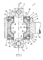
- FIG. Shows a longitudinal section through a fully assembled spherical plain bearing.
- the spherical plain bearing 1 shows a spherical plain bearing 1 of a motor vehicle.
- the spherical plain bearing 1 consists of a metallic inner part 2, a receiving eye 3 and a rubber-metal element 4 clamped between them under pretension.
- the metallic inner part 2 is elongated and has fastening arms 5, 6 on both sides with holes for screw fastening on a motor vehicle body. Towards the center there are cylindrically shaped sections 7, 8 which merge into a thickening 9 towards the center.
- the thickening 9 is formed rotationally symmetrically about a longitudinal axis 10 of the bearing with a central, cylindrical region 11 and with surface regions 1, 13 which decrease in cross section to the side.
- the receiving eye 3 has a cylindrical interior, with radially circumferential grooves for receiving circlips 14, 15 being introduced in the lateral edge region.
- the rubber-metal body 4 is divided in a radial plane in the middle of the thickening 9 into two mirror parts of the same shell parts 16, 17, so that both shell parts can be pushed onto the thickening from the end faces.
- a rubber layer 20, 21 is vulcanized onto a correspondingly divided inner tube 18, 19 made of plastic material, the outer circumferential surface of which has approximately the shape of the interior of the receiving eye 3 (even in the unloaded state).
- the inner tube 18, 19 corresponds to the shape of the metallic inner part 2 in the region of the sections 7, 8 and the thickening 9 and is slidably mounted on these surfaces.
- a metallic pressure ring 22, 23 is vulcanized onto both sides of the shell parts 16, 17 and the rubber layers 20, 21.
- the pressure ring has an inclined surface area toward the center of the bearing with an inner edge flange 24 running parallel to the longitudinal axis of the bearing and an outer edge flange 25 standing transversely thereto.
- the pressure rings 22, 23 lie in a radially outer area of the rubber layer 20, 21.
- the rubber layer 20, 21 is already shown in FIG. 1 in the clamped and fully assembled state after the pressure rings 22, 23 have been pressed together in the axial direction. It follows from this that in the unloaded state the pressure rings 22, 23 have been located further to the side and the bulging of the rubber layers 20, 21 shown to the side is only generated by the prestressing. In order to obtain a good contact of the inner tube parts 18, 19 with the thickening 9 as well as a good, flat contact of the two rubber layers 20, 21, a gap 26 is provided between the inner tube parts 18, 19.
- Sealing components 28, 29, which each consist of a first bearing ring 30, 31, a second bearing ring 32, 33 and a vulcanized rubber wall 34, 35 between the bearing rings, are placed on both end faces of the spherical bearing 1.
- the first bearing rings 30, 31 are pressed tightly and firmly on the end face onto the metallic inner part in the region of the cylindrical sections 7 and lie against the end on the inner tube parts 18, 19.
- the second bearing rings 32, 33 are also tightly and firmly pressed onto the receiving eye 3 on the inside face.
- the rubber walls 34, 35 have a slight constriction in the middle between the bearing rings.
- the joint bearing 1 shown has the following function:
- the end areas between the inner part 9 and the receiving eye 3, i.e. the inner region of the spherical bearing 1 are protected from environmental influences by the sealing components 28, 29. Relative movements of the bearing parts are recorded in the rubber walls 34, 35 without kinks and wrinkles.
- the end faces are flat and smooth without protruding and easily vulnerable bellows bulges.
- the first bearing rings 30, 31 and their end support of the inner tube parts 18, 19 prevent the plastic material of the inner tube parts 18, 19 used as a sliding layer from flowing away axially, so that the thickness of the sliding layer is advantageously retained even after long use.
Landscapes
- Engineering & Computer Science (AREA)
- General Engineering & Computer Science (AREA)
- Mechanical Engineering (AREA)
- Support Of The Bearing (AREA)
- Pivots And Pivotal Connections (AREA)
- Power Steering Mechanism (AREA)
- Sliding-Contact Bearings (AREA)
- Rolling Contact Bearings (AREA)
Claims (11)
Priority Applications (1)
| Application Number | Priority Date | Filing Date | Title |
|---|---|---|---|
| AT89112616T ATE60008T1 (de) | 1988-07-16 | 1989-07-11 | Gelenklager, insbesondere fuer einen achslenker eines kraftfahrzeugs. |
Applications Claiming Priority (2)
| Application Number | Priority Date | Filing Date | Title |
|---|---|---|---|
| DE3824271 | 1988-07-16 | ||
| DE3824271A DE3824271A1 (de) | 1988-07-16 | 1988-07-16 | Gelenklager, insbesondere fuer einen achslenker eines kraftfahrzeugs |
Publications (2)
| Publication Number | Publication Date |
|---|---|
| EP0351689A1 EP0351689A1 (fr) | 1990-01-24 |
| EP0351689B1 true EP0351689B1 (fr) | 1991-01-16 |
Family
ID=6358899
Family Applications (1)
| Application Number | Title | Priority Date | Filing Date |
|---|---|---|---|
| EP89112616A Expired - Lifetime EP0351689B1 (fr) | 1988-07-16 | 1989-07-11 | Palier à articulation, en particulier pour un guide d'essieu de véhicule automobile |
Country Status (3)
| Country | Link |
|---|---|
| EP (1) | EP0351689B1 (fr) |
| AT (1) | ATE60008T1 (fr) |
| DE (2) | DE3824271A1 (fr) |
Families Citing this family (20)
| Publication number | Priority date | Publication date | Assignee | Title |
|---|---|---|---|---|
| DE4142030C2 (de) * | 1991-12-19 | 1993-10-07 | Joern Gmbh | Abdichtung des Lagerinnenraums eines Schwenklagers |
| FR2691767A1 (fr) * | 1992-05-27 | 1993-12-03 | Hutchinson | Dispositif de liaison élastique à rotule. |
| DE4304775C2 (de) * | 1993-02-17 | 1997-02-13 | Trw Fahrwerksyst Gmbh & Co | Gelenklager |
| US5931597A (en) * | 1997-10-16 | 1999-08-03 | Trw Inc. | Ball joint |
| DE19755284A1 (de) * | 1997-12-22 | 1999-06-24 | Schaeffler Waelzlager Ohg | Kugelgelenk |
| SE515045C2 (sv) * | 1999-10-08 | 2001-06-05 | Trelleborg Ab | Bussning till stag |
| US6533490B2 (en) * | 2001-01-05 | 2003-03-18 | American Axle & Manufacturing, Inc. | Isolation ball joint for steering and suspension |
| DE50306617D1 (de) * | 2002-01-22 | 2007-04-12 | Rempel Stanztechnik Gmbh & Co | Konstruktionselement, insbesondere für die Lenkgeometrie von Strassenfahrzeugen |
| DE10222950B4 (de) * | 2002-05-24 | 2008-07-31 | Zf Boge Elastmetall Gmbh | Kugelgelenk |
| DE102009016139A1 (de) | 2009-04-03 | 2010-10-14 | Trw Automotive Gmbh | Elastomergelenk |
| DE102009026739A1 (de) * | 2009-06-04 | 2010-12-09 | Zf Friedrichshafen Ag | Gelenk- und/oder Lageranordnung mit einer elastischen Zwischenlage |
| DE102010052872B4 (de) | 2010-12-01 | 2023-04-27 | THK RHYTHM AUTOMOTIVE GmbH | Elastomergelenk |
| DE102016203741B3 (de) * | 2016-03-08 | 2017-04-13 | Zf Friedrichshafen Ag | Kugelgelenk |
| DE102017222821B4 (de) * | 2017-12-14 | 2022-10-06 | Volkswagen Aktiengesellschaft | Lagervorrichtung, Aggregatträgersystem und Kraftfahrzeug |
| DE102018218266A1 (de) * | 2018-10-25 | 2020-04-30 | Zf Friedrichshafen Ag | Innenteil für ein Molekulargelenk eines Fahrwerklenkers |
| CN110273955B (zh) * | 2019-06-21 | 2021-01-22 | 株洲时代新材料科技股份有限公司 | 横向拉杆节点、横向拉杆节点组件及其刚度调节方法 |
| US11859657B2 (en) * | 2020-03-02 | 2024-01-02 | Federal-Mogul Motorparts Llc | Socket assembly with a retention device |
| JP6966599B1 (ja) * | 2020-05-29 | 2021-11-17 | 住友理工株式会社 | 鉄道台車用ゴムブッシュ |
| DE102021203194B3 (de) | 2021-03-30 | 2022-07-21 | Zf Friedrichshafen Ag | Kugelgelenk und Fahrwerkbauteil für ein Kraftfahrzeug und mit einem solchen Kugelgelenk |
| DE102021129206B4 (de) * | 2021-11-10 | 2024-02-15 | Jörn GmbH | Kugelgelenk, insbesondere für Fahrzeuge |
Family Cites Families (9)
| Publication number | Priority date | Publication date | Assignee | Title |
|---|---|---|---|---|
| GB576173A (en) * | 1944-02-21 | 1946-03-21 | Silentbloc | Improvements in or relating to flexible or shock absorbing mountings |
| GB621355A (en) * | 1947-02-21 | 1949-04-07 | Noel Banner Newton | Improvements in or relating to resilient mounting bushes |
| GB637901A (en) * | 1948-03-23 | 1950-05-31 | Silentbloc | Improvements in or relating to self-aligning joints or bearings |
| DE1047036B (de) * | 1956-11-17 | 1958-12-18 | Auto Union Gmbh | Spurstangenkopf, insbesondere fuer Kraftfahrzeuglenkungen |
| FR1439913A (fr) * | 1965-02-20 | 1966-05-27 | Pneumatiques, Caoutchouc Manufacture Et Plastiques Kleber-Colombes | Articulation élastique |
| US3680924A (en) * | 1970-03-06 | 1972-08-01 | Us Army | Endless track pin assembly |
| DE2144507C2 (de) * | 1971-09-06 | 1983-09-08 | Jörn, Raoul, Dipl.-Ing., 8992 Hengnau | Gelenklager |
| DE2434501A1 (de) * | 1974-07-18 | 1976-01-29 | Diehl Fa | Gummigelagertes kugelgelenk |
| DE3419967C2 (de) * | 1984-05-29 | 1986-07-10 | Boge Gmbh, 5208 Eitorf | Elastisches Gelenk, Kupplung oder dergleichen |
-
1988
- 1988-07-16 DE DE3824271A patent/DE3824271A1/de not_active Withdrawn
-
1989
- 1989-07-11 DE DE8989112616T patent/DE58900045D1/de not_active Expired - Lifetime
- 1989-07-11 AT AT89112616T patent/ATE60008T1/de not_active IP Right Cessation
- 1989-07-11 EP EP89112616A patent/EP0351689B1/fr not_active Expired - Lifetime
Also Published As
| Publication number | Publication date |
|---|---|
| DE58900045D1 (de) | 1991-02-21 |
| EP0351689A1 (fr) | 1990-01-24 |
| ATE60008T1 (de) | 1991-02-15 |
| DE3824271A1 (de) | 1990-03-29 |
Similar Documents
| Publication | Publication Date | Title |
|---|---|---|
| EP0351689B1 (fr) | Palier à articulation, en particulier pour un guide d'essieu de véhicule automobile | |
| EP0353347B1 (fr) | Articulation, en particulier pour la bielle d'asservissement des essieux d'un véhicule à moteur | |
| EP0147662B1 (fr) | Palier élastique à mouvement contraint | |
| EP0163980B1 (fr) | Articulation, accouplement élastique ou similaires | |
| DE4120772C2 (de) | Radial und axial belastbares Drehgleitlager für Fahrwerksteile in Kraftfahrzeugen | |
| EP0570625A2 (fr) | Palier pivotant | |
| EP1586789A1 (fr) | Support élastique pour une cabine de véhicule | |
| EP0493731B1 (fr) | Flexibloc pour articulation | |
| DE2140124C2 (de) | Elastische Lagerbüchse | |
| EP1031756A2 (fr) | Fixation d'un soufflet roulant d'un ressort pneumatique sur un élément de support | |
| DE4128488A1 (de) | Doppelquerlenker-vorderachsfuehrung | |
| DE4322304C1 (de) | Gelenklager, insbesondere für einen Achslenker eines Kraftfahrzeugs | |
| DE4127092C1 (en) | Joint bearing for car axle link - has outer tube and associated rubber layer separated in axial bearing centre to form cylindrical intermediate space | |
| DE3906079A1 (de) | Elastischer aufhaengepuffer | |
| EP1691104A1 (fr) | Support élastique | |
| EP1118791B1 (fr) | Articulation à manchon de métal et élastomère | |
| EP0373307B1 (fr) | Articulation, en particulier pour la bielle d'asservissement des essieux d'un véhicule à moteur | |
| EP0229940A2 (fr) | Support élastique pour le montage d'une cabine de chauffeur de camion | |
| DE4420489C2 (de) | Kugelgelenk | |
| EP0770792A1 (fr) | Unité cylindre-piston rempli avec un fluide, en particulier ressort à gaz | |
| EP0748949B1 (fr) | Support radial | |
| DE8112477U1 (de) | "Elastisches Gelenkwellen-Zwischenlager" | |
| EP0809039A1 (fr) | Ressort du type à manchon de caoutchouc | |
| EP1820994B1 (fr) | Pendule, en particulier pour le train d'atterrissage d'un véhicule utilitaire | |
| DE7327342U (de) | Gummi-Metall-Buchse |
Legal Events
| Date | Code | Title | Description |
|---|---|---|---|
| PUAI | Public reference made under article 153(3) epc to a published international application that has entered the european phase |
Free format text: ORIGINAL CODE: 0009012 |
|
| AK | Designated contracting states |
Kind code of ref document: A1 Designated state(s): AT DE FR GB IT NL |
|
| 17P | Request for examination filed |
Effective date: 19900213 |
|
| 17Q | First examination report despatched |
Effective date: 19900629 |
|
| GRAA | (expected) grant |
Free format text: ORIGINAL CODE: 0009210 |
|
| AK | Designated contracting states |
Kind code of ref document: B1 Designated state(s): AT DE FR GB IT NL |
|
| PG25 | Lapsed in a contracting state [announced via postgrant information from national office to epo] |
Ref country code: GB Effective date: 19910116 |
|
| REF | Corresponds to: |
Ref document number: 60008 Country of ref document: AT Date of ref document: 19910215 Kind code of ref document: T |
|
| REF | Corresponds to: |
Ref document number: 58900045 Country of ref document: DE Date of ref document: 19910221 |
|
| ITF | It: translation for a ep patent filed |
Owner name: ING. C. GREGORJ S.P.A. |
|
| ET | Fr: translation filed | ||
| GBV | Gb: ep patent (uk) treated as always having been void in accordance with gb section 77(7)/1977 [no translation filed] | ||
| PLBE | No opposition filed within time limit |
Free format text: ORIGINAL CODE: 0009261 |
|
| STAA | Information on the status of an ep patent application or granted ep patent |
Free format text: STATUS: NO OPPOSITION FILED WITHIN TIME LIMIT |
|
| 26N | No opposition filed | ||
| PGFP | Annual fee paid to national office [announced via postgrant information from national office to epo] |
Ref country code: NL Payment date: 19920731 Year of fee payment: 4 Ref country code: FR Payment date: 19920731 Year of fee payment: 4 Ref country code: AT Payment date: 19920731 Year of fee payment: 4 |
|
| PG25 | Lapsed in a contracting state [announced via postgrant information from national office to epo] |
Ref country code: AT Effective date: 19930711 |
|
| PG25 | Lapsed in a contracting state [announced via postgrant information from national office to epo] |
Ref country code: NL Effective date: 19940201 |
|
| NLV4 | Nl: lapsed or anulled due to non-payment of the annual fee | ||
| PG25 | Lapsed in a contracting state [announced via postgrant information from national office to epo] |
Ref country code: FR Effective date: 19940331 |
|
| REG | Reference to a national code |
Ref country code: FR Ref legal event code: ST |
|
| PGFP | Annual fee paid to national office [announced via postgrant information from national office to epo] |
Ref country code: DE Payment date: 20020806 Year of fee payment: 14 |
|
| PG25 | Lapsed in a contracting state [announced via postgrant information from national office to epo] |
Ref country code: DE Free format text: LAPSE BECAUSE OF NON-PAYMENT OF DUE FEES Effective date: 20040203 |
|
| PG25 | Lapsed in a contracting state [announced via postgrant information from national office to epo] |
Ref country code: IT Free format text: LAPSE BECAUSE OF NON-PAYMENT OF DUE FEES;WARNING: LAPSES OF ITALIAN PATENTS WITH EFFECTIVE DATE BEFORE 2007 MAY HAVE OCCURRED AT ANY TIME BEFORE 2007. THE CORRECT EFFECTIVE DATE MAY BE DIFFERENT FROM THE ONE RECORDED. Effective date: 20050711 |