EP0350899A2 - Durch Verankerung zusammengesetzte Strukturen und Verfahren zur Herstellung - Google Patents
Durch Verankerung zusammengesetzte Strukturen und Verfahren zur Herstellung Download PDFInfo
- Publication number
- EP0350899A2 EP0350899A2 EP89112770A EP89112770A EP0350899A2 EP 0350899 A2 EP0350899 A2 EP 0350899A2 EP 89112770 A EP89112770 A EP 89112770A EP 89112770 A EP89112770 A EP 89112770A EP 0350899 A2 EP0350899 A2 EP 0350899A2
- Authority
- EP
- European Patent Office
- Prior art keywords
- anchor
- cavities
- base plate
- plate
- cladding
- Prior art date
- Legal status (The legal status is an assumption and is not a legal conclusion. Google has not performed a legal analysis and makes no representation as to the accuracy of the status listed.)
- Withdrawn
Links
Images


Classifications
-
- B—PERFORMING OPERATIONS; TRANSPORTING
- B21—MECHANICAL METAL-WORKING WITHOUT ESSENTIALLY REMOVING MATERIAL; PUNCHING METAL
- B21D—WORKING OR PROCESSING OF SHEET METAL OR METAL TUBES, RODS OR PROFILES WITHOUT ESSENTIALLY REMOVING MATERIAL; PUNCHING METAL
- B21D39/00—Application of procedures in order to connect objects or parts, e.g. coating with sheet metal otherwise than by plating; Tube expanders
- B21D39/03—Application of procedures in order to connect objects or parts, e.g. coating with sheet metal otherwise than by plating; Tube expanders of sheet metal otherwise than by folding
Definitions
- This invention relates generally to composite structures each produced by joining two or more separate materials to form a single unitary structure. More particularly the invention concerns composite structures each fabricated by strongly joining a cladding plate to a substrate or base plate to obtain an integral structure.
- a cladding plate is made of aluminum or an alloy thereof.
- An example of the material for the base plate is steel.
- Examples of products which can be advantageously made of such composite structures are plate materials for tanks of LNG transport ships and reaction plates for linear motor vehicles.
- the invention relates to anchor bonded composite structures each comprising a hard substrate or base plate made of a material such as steel and a relatively soft cladding plate made of a material such as an aluminum alloy and having a plurality of anchor parts which are forced under great pressing force into corresponding anchor cavities in the base plate, whereby the two plates are joined firmly to form a unitary structure.
- the invention relates also to a process for producing these anchor bonded composite structures.
- An important feature of the invention is that, at the deepest portion of each anchor cavity in the base plate, one or more overhanging parts are formed, whereby, when the corresponding anchor part of the cladding is forced under great pressing force into this anchor cavity, the anchor part undergoes plastic deformation to assume a sectional shape of the letter T or Y in inverted state which completely fills the anchor cavity. Thus a positively locking joint or anchor bond is produced.
- the anchor bonds of plural number join the two plates as an integral structure.
- laminated metal structures are becoming widely used as materials in various machines, devices, and structures.
- Examples, as mentioned hereinbefore, are reaction plates for linear motor cars and tank materials of LNG transport vessels. All required characteristics such as mechanical strength, corrosion resistance, behavior relative to heat, and elongation/contraction properties cannot be completely satisfied by a plate material of a single substance. Accordingly it is becoming a widely spreading practice to use plate materials produced by firmly joining base plates of hard steel and cladding plates of soft aluminum alloy to obtain an integral plate structure.
- Still another problem has been slippage at the interface between the two plates due to severe conditions of use such as vibration over a long period.
- composite structures each of which is produced by anchor bonding into an integral plate structure a base plate of steel and a cladding plate of aluminum, and in which the two plates are joined in a locked state by anchors integral with the cladding plate forcibly inserted into and plasticly deformed in corresponding anchor cavities formed in the base plate, the anchors and/or the anchor cavities having overhanging or catching parts affording a positive locking or anchoring joint between the two plates.
- anchor cavities to be mutually confronting and aligned are formed with overhanging parts respectively in the base plate and the cladding plate and then filled with a rivet-like or hour-glass-shaped anchor pin.
- the anchor cavities are formed by any suitable process such as forging, rolling, or machining.
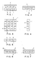
- each of these composite structures comprises, essentially a steel base plate 1 and an aluminum alloy cladding plate 2 joined tightly by anchor bonding to the base plate to form the unitary composite structure. More specifically the two plates are anchor bonded at their respective anchor parts as will now be described in detail with respect to several examples constituting preferred embodiments of the invention.
- the steel base plate 1 is a square plate, and the cladding plate 2 of aluminum is of the same shape in plan view.
- a number of parallel and spaced-apart grooves 3, 3, ... of specific width, spacing and cross-sectional shape are formed in a first direction (these grooves being referred to hereinafter as first grooves), as shown in FIGS. 1, 3, and 5.
- a number of parallel and spaced-apart grooves 4, 4, ... of specific narrow width and spacing are formed in a second direction perpendicular to the first direction (these narrow grooves being referred to hereinafter as second grooves).
- Each of the first grooves 3, 3, ... has a split-bottom shape with a ridge-like projection 3 , similar to the capital letter Y in inverted state, whereby an anchor cavity 5 with overhanging lips 5a is formed along that first groove between each pair of adjacent second grooves.
- protruding ribs 6, 6, ... of grid network form to become anchor parts are formed integrally on one (bottom) face of the cladding plate 2 in positions to be in alignment with corresponding anchor grooves 3, 3, ... and 4, 4, ...
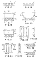
- first anchor grooves 3a as shown in FIGS. 10 and 11 are used.
- Each of these grooves 3a is formed by plastic deformation to have flanking walls of curved wave-like shape.
- anchor depressions or holes 9, 9, ... of inwardly tapering shape are formed in the same face of the base plate 1 on opposite sides of each anchor groove 3a at specific spacing intervals.
- a cladding plate 2 which is similar to that in the preceding example and has protruding ribs 6 to align with respective anchor grooves 3a is prepared and pressed under great pressure against the base plate 1.
- the cladding plate 2 is integrally joined to the base plate 1 by anchor bonds 7 to produce a unitary composite structure 8a as shown in FIGS. 12, 13, and 14.
- this composite structure 8a also, there is no possibility of slippage in the first and/or second directions between the cladding plate 2 and the base plate 1 due to causes such as vibration and thermal action.
- a composite structure 8a of stable mechanically bonded state is obtained.
- first grooves 3 are formed in the base plate 1 by annular protruding parts 10a of a rolling roll 10.
- projections 13 of truncated triangular shape in section are formed with a specific spacing pitch on the bottoms of the first grooves 3 by grooves 12, 12 formed with a specific spacing in the circumferential direction on the protruding parts 10a of the roll 10.
- the surface of the base plate 1 is rolled by another rolling roll 10b thereby to flatten the upwardly rising parts 11 formed on the two edges at the upper part of each first groove 3.
- anchor cavities 5 having overhangs can be formed.
- projections 13 of the shape of a truncated triangle in section are formed with a specific spacing in the longitudinal direction of the anchor cavities 5.
- the anchor bond 7 produced by the forcible fitting of the anchors 6 of the cladding plate 2 into the anchor cavities 5 of the base plate 1 is further prevented from undergoing slippage in the longitudinal direction by the projections, 13, 13, ..., whereby its resistance to shear stress is further increased.
- anchor cavities 5 in the base plate 1 in each of the above described examples a rolling roll as indicated in FIGS. 19, 20, and 21 is used.
- these anchor cavities are not limited to a pattern of linear rows but may be in a pattern of intermittent or spotty cavities.
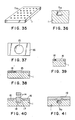
- tapered anchor cavities 5a and 5b having overhanging parts as shown in FIGS. 29 and 31 are formed respectively in the base plate 1 and the cladding plate 2 at coincidently aligned positions which are in a regular pattern as shown in FIGS. 28 and 30.
- Each anchor cavity 5a in the base plate 1 can thus be coaxially aligned with a corresponding anchor cavity or hole 5b in the cladding plate as shown in FIG. 32.
- an anchor pin 14 is inserted into the aligned anchor cavities 5a and 5b and is pressed by means of a rolling roll 10b or means such as a press, forcing the anchor pin 14 into the anchor cavities 5b and 5a.
- the anchor pins 14 are plasticly deformed to fill the anchor cavities, whereby an anchor bond 7a is formed, each as shown in FIG. 34, and the cladding plate 2 and the base plate 1 are mechanically bonded to form a unitary structure 8c.
- FIGS. 35 through 41 Another mode of producing an anchor bonded structure is illustrated in FIGS. 35 through 41.
- the base plate 1 is fabricated, as indicated in FIGS. 37, 38, and 39, by placing a forming plate 16 with a circular hole formed therethrough on a position on the base plate 1 where an anchor cavity 5a is to be formed, placing a punch 14 of a diameter smaller than that of the circular hole 15 on the base plate 1 concentrically with the circular hole 15, and applying a punching force on the punch 14 thereby to force metal of the base plate 1 to rise upward and thus to form an upwardly raised mound 17, a punched hole 18 being formed at the same time in the base plate 1. Thereafter, as indicated in FIG.
- a leveling plate 19 is placed over the region of the base plate 1 thus processed and pressed thereagainst.
- the upwardly raised mound 17 is forced to flow inward, and an anchor cavity 5a of an overhanging shape is formed as shown in FIG. 36.
- a plurality of intermittent anchor cavities 5a spaced apart in a regular pattern are formed in the base plate 1 as shown in FIG. 35.
- a circular hole 22 is first formed in the base plate 1 by suitable means such as a milling machine. Then a rotary tool holder 20 comprising a rotor 21 and a plurality of cutting tools 23, 23, ... retractably imbedded in the lower periphery of the rotor 21 is inserted coaxially into the hole 22 as shown in FIG. 43. The rotary tool holder 20 is then rotated as the cutting tools 23, 23, ... are progressively extended outward as indicated in FIG. 44 thereby to mechanically form an anchor cavity 5b of overhanging shape as shown in FIGS. 5, 46, and 47.
- anchor cavities are to be anchor cavities 5a of linear row form or whether they are to be anchor cavities 5b of spot form, they can be formed in overhanging shape by rolling in the following manner.
- annular protruding parts 10a of a rolling roll as shown in FIGS. 19 and 20 referred to hereinbefore and as indicated in FIG. 48, a pressing force is imparted to the base plate 1 thereby to form first grooves 3 (or second grooves 4).
- forced up parts 17 are formed on the upper surface of the base plate 1 on both sides of each protruding part 10a.
- the forced up parts 17 are abruptly flattened in the succeeding stage by means of a plan roll for leveling thereby to form anchor cavities of overhanging shape.
- the overhanging shape has been irregular, or has collapsed.
- the forced up parts 17 are rolled by means of a forming roll 10c as indicated in FIG. 49, whereby they are caused to flow and bend gently inward. Finally, as indicated in FIG. 50, these parts are leveled by a plain roll 10b. As a result, all of the anchor cavities 5a are formed into overhanging shape accurately and consistently exactly as designed.
- an anchor-bond integral joining can be obtained mechanically by the fitting and engagement of anchors of a cladding plate in corresponding anchor cavities in a base plate. For this reason, by the fitting and engagement in two orthogonal directions of these anchor cavities and anchors, the resistance to shear stress in the longitudinal direction is remarkably increased, and the initial bonding strength is maintained unchanged with lapse of time, whereby the functional performance of the resulting structure is continually maintained.
- the bonding function of the bonded structure is made uniform, and the performances of bonded structures of long length or large areas can be further improved.
Landscapes
- Engineering & Computer Science (AREA)
- Mechanical Engineering (AREA)
- Pressure Welding/Diffusion-Bonding (AREA)
- Linear Motors (AREA)
- Laminated Bodies (AREA)
- Joining Of Building Structures In Genera (AREA)
Applications Claiming Priority (2)
| Application Number | Priority Date | Filing Date | Title |
|---|---|---|---|
| JP63172645A JP2632375B2 (ja) | 1988-07-13 | 1988-07-13 | アンカーボンド接合体及びその製造方法 |
| JP172645/88 | 1988-07-13 |
Publications (2)
| Publication Number | Publication Date |
|---|---|
| EP0350899A2 true EP0350899A2 (de) | 1990-01-17 |
| EP0350899A3 EP0350899A3 (de) | 1990-11-14 |
Family
ID=15945725
Family Applications (1)
| Application Number | Title | Priority Date | Filing Date |
|---|---|---|---|
| EP19890112770 Withdrawn EP0350899A3 (de) | 1988-07-13 | 1989-07-12 | Durch Verankerung zusammengesetzte Strukturen und Verfahren zur Herstellung |
Country Status (6)
| Country | Link |
|---|---|
| EP (1) | EP0350899A3 (de) |
| JP (1) | JP2632375B2 (de) |
| KR (1) | KR940002013B1 (de) |
| CN (1) | CN1019041B (de) |
| AU (1) | AU611310B2 (de) |
| CA (1) | CA1315917C (de) |
Cited By (3)
| Publication number | Priority date | Publication date | Assignee | Title |
|---|---|---|---|---|
| CN1043411C (zh) * | 1993-02-01 | 1999-05-19 | 卡劳公司 | 旋锻用的圆环及其制造方法 |
| WO2003026816A1 (fr) * | 2001-09-20 | 2003-04-03 | The Foundation For The Promotion Of Industrial Science | Corps connecte et procede de connexion |
| DE102004029230A1 (de) * | 2004-06-17 | 2006-01-12 | Thyssenkrupp Stahl Ag | Verfahren zum Verbinden von zwei insbesondere aus Metall bestehenden Fügepartnern mittels Überlappstoß und durch Fügen hergestelltes Bauteil |
Families Citing this family (14)
| Publication number | Priority date | Publication date | Assignee | Title |
|---|---|---|---|---|
| JP2649132B2 (ja) * | 1993-01-20 | 1997-09-03 | 川崎重工業株式会社 | リアクションプレート及びその製造方法 |
| AU2003207126A1 (en) * | 2003-01-16 | 2004-08-10 | Shenyang Jianbaoli New Building Material Co., Ltd | New type building exterior panel, process and apparatus for making the same |
| JP4501408B2 (ja) * | 2003-10-30 | 2010-07-14 | アイシン精機株式会社 | 締結方法 |
| CN100400899C (zh) * | 2005-12-14 | 2008-07-09 | 中国科学院金属研究所 | 一种微小部件机械联接方法 |
| JP5527911B1 (ja) * | 2013-02-15 | 2014-06-25 | 防衛省技術研究本部長 | 抵抗翼の係止構造体 |
| CN103434197B (zh) * | 2013-07-18 | 2015-10-14 | 浙江中隧桥波形钢腹板有限公司 | 锚勾式复合防腐金属构件及制备工艺 |
| KR20170139533A (ko) * | 2015-04-24 | 2017-12-19 | 스미토모덴키고교가부시키가이샤 | 복합 재료 및 그의 제조 방법 |
| US11141929B2 (en) | 2015-11-13 | 2021-10-12 | Nec Platforms, Ltd. | Fixing object, fixation item, fixing method, and assessment method |
| CN106994813A (zh) * | 2016-01-25 | 2017-08-01 | 林暄智 | 复合金属成形方法及其结构 |
| CN107377792A (zh) * | 2017-08-31 | 2017-11-24 | 佛山市三水和美斯金铝业有限公司 | 铝家具板材生产方法 |
| CN108115369B (zh) * | 2018-01-17 | 2020-02-11 | 广东长盈精密技术有限公司 | 手机中框加工工艺 |
| EP3823822A4 (de) | 2018-07-20 | 2022-03-23 | 10856479 Canada Inc. | Kombinierte folien und verfahren und system zu ihrer herstellung |
| CN110410399A (zh) * | 2019-07-05 | 2019-11-05 | 浙江理工大学 | 一种内嵌式变形连接方法 |
| WO2024218594A1 (en) * | 2023-04-17 | 2024-10-24 | 3M Innovative Properties Company | Anchor array |
Family Cites Families (7)
| Publication number | Priority date | Publication date | Assignee | Title |
|---|---|---|---|---|
| US1367134A (en) * | 1918-12-30 | 1921-02-01 | Herman Stifel | Joint |
| DE455259C (de) * | 1926-10-08 | 1928-01-27 | Hydraulik G M B H | Pressplatte mit Heizkanaelen |
| FR872779A (fr) * | 1939-09-27 | 1942-06-18 | Dortmund Hoerder Hu Ttenver Ag | Procédé de fabrication de récipients frettés pour hautes pressions et frettes pour sa mise en oeuvre |
| JPS453645Y1 (de) * | 1965-11-19 | 1970-02-19 | ||
| AU503128B2 (en) * | 1975-12-09 | 1979-08-23 | John Lysaght (Australia) Limited | Method of butt joinig two sheets |
| JPS60250872A (ja) * | 1984-05-25 | 1985-12-11 | 彭 大雄 | ポンチにおけるシヤンクとタングステンカ−バイドチツプのろう付け法 |
| KR900004783B1 (ko) * | 1987-07-01 | 1990-07-05 | 가와사끼 쥬고교 주식회사 | 이종재료의 중합체 및 그 제조방법 |
-
1988
- 1988-07-13 JP JP63172645A patent/JP2632375B2/ja not_active Expired - Lifetime
-
1989
- 1989-07-12 AU AU38064/89A patent/AU611310B2/en not_active Ceased
- 1989-07-12 EP EP19890112770 patent/EP0350899A3/de not_active Withdrawn
- 1989-07-13 KR KR1019890009974A patent/KR940002013B1/ko not_active Expired - Fee Related
- 1989-07-13 CA CA000605607A patent/CA1315917C/en not_active Expired - Fee Related
- 1989-07-13 CN CN89104835A patent/CN1019041B/zh not_active Expired
Cited By (3)
| Publication number | Priority date | Publication date | Assignee | Title |
|---|---|---|---|---|
| CN1043411C (zh) * | 1993-02-01 | 1999-05-19 | 卡劳公司 | 旋锻用的圆环及其制造方法 |
| WO2003026816A1 (fr) * | 2001-09-20 | 2003-04-03 | The Foundation For The Promotion Of Industrial Science | Corps connecte et procede de connexion |
| DE102004029230A1 (de) * | 2004-06-17 | 2006-01-12 | Thyssenkrupp Stahl Ag | Verfahren zum Verbinden von zwei insbesondere aus Metall bestehenden Fügepartnern mittels Überlappstoß und durch Fügen hergestelltes Bauteil |
Also Published As
| Publication number | Publication date |
|---|---|
| CA1315917C (en) | 1993-04-13 |
| JPH0225228A (ja) | 1990-01-26 |
| JP2632375B2 (ja) | 1997-07-23 |
| CN1019041B (zh) | 1992-11-11 |
| AU611310B2 (en) | 1991-06-06 |
| CN1041028A (zh) | 1990-04-04 |
| EP0350899A3 (de) | 1990-11-14 |
| KR940002013B1 (ko) | 1994-03-14 |
| KR900001990A (ko) | 1990-02-28 |
| AU3806489A (en) | 1990-05-31 |
Similar Documents
| Publication | Publication Date | Title |
|---|---|---|
| US5121537A (en) | Method of production of anchor-bonded composite structures | |
| EP0350899A2 (de) | Durch Verankerung zusammengesetzte Strukturen und Verfahren zur Herstellung | |
| US4690599A (en) | Self-piercing nut | |
| US5305517A (en) | Apparatus for forming clinch joints | |
| KR900004783B1 (ko) | 이종재료의 중합체 및 그 제조방법 | |
| EP0350927B1 (de) | Zusammengesetzte Stabstrukturen aus mehreren miteinander verbundenen Teilen und Verfahren zu ihrer Herstellung | |
| JP3543267B2 (ja) | アルミ製打込みリベット | |
| KR20190031933A (ko) | 셀프 피어싱 클린칭 너트 | |
| JP3224502B2 (ja) | 積層金属板のプレス用金型 | |
| US3187424A (en) | Method of applying a fastener | |
| US5870923A (en) | Forging method | |
| JP2019166564A (ja) | 接合装置および接合体の製造方法 | |
| JP2926223B2 (ja) | アンカーボンド接合用板体及びその製造方法 | |
| JPH0368770B2 (de) | ||
| JPH02280926A (ja) | だれ・かえり防止打抜き加工法 | |
| JP2007237201A (ja) | 接合良否判定方法及び接合装置 | |
| CN214578135U (zh) | 铆接结构 | |
| JP2816645B2 (ja) | ピアスナット | |
| JP2824408B2 (ja) | 金属部品の接合方法 | |
| JP2849823B2 (ja) | 金属板のバーリング/シェービング複合成形物及びその成形方法 | |
| KR100397843B1 (ko) | 박판페어의 기계적 접합을 위한 장치 | |
| JPH0229405B2 (de) | ||
| JPH03138046A (ja) | 複数材料の回転鍛造接合方法 | |
| JP2614593B2 (ja) | アイ形ジョイントの製造方法 | |
| KR19980072021A (ko) | 철재 체결방법 및 장치 |
Legal Events
| Date | Code | Title | Description |
|---|---|---|---|
| PUAI | Public reference made under article 153(3) epc to a published international application that has entered the european phase |
Free format text: ORIGINAL CODE: 0009012 |
|
| 17P | Request for examination filed |
Effective date: 19890712 |
|
| AK | Designated contracting states |
Kind code of ref document: A2 Designated state(s): DE FR GB IT NL |
|
| PUAL | Search report despatched |
Free format text: ORIGINAL CODE: 0009013 |
|
| AK | Designated contracting states |
Kind code of ref document: A3 Designated state(s): DE FR GB IT NL |
|
| 17Q | First examination report despatched |
Effective date: 19920406 |
|
| STAA | Information on the status of an ep patent application or granted ep patent |
Free format text: STATUS: THE APPLICATION IS DEEMED TO BE WITHDRAWN |
|
| 18D | Application deemed to be withdrawn |
Effective date: 19920818 |